3G_Pre-launch Optimization Guidelines ppsx
Bạn đang xem bản rút gọn của tài liệu. Xem và tải ngay bản đầy đủ của tài liệu tại đây (1.53 MB, 93 trang )
GUIDELINES Version Status
RF Optimization Guideline for AMX 3G Rollout 1
Consulting and System Integrations August, 27
th
2007 Revised by: Danilo Cabral
Raj Sandhu, Allan Bispo and Daniel Platero
GUIDELINE for 3G RF OPTIMIZATION
America Movil LATAM Projects
Owner: NSN
Scope: Guidelines
Originator: Raj Sandhu, Allan Bispo and Daniel Platero
Revised by: Danilo Cabral
Status: Version 1.1
Document ID:
Location: NSN BR
GUIDELINES Version Status
RF Optimization Guideline for AMX 3G Rollout 1
Consulting and System Integrations August, 27
th
2007 Revised by: Danilo Cabral
Raj Sandhu, Allan Bispo and Daniel Platero
Table of Content
DOCUMENT HISTORY 5
1. Introduction 6
1.1 Purpose 6
1.2 Overview 6
2. RF Cluster Acceptance 8
2.1 Preparation Phase 8
2.1.1 Compilation of planning data 9
2.1.2 Site Clustering 9
2.1.3 Drive Routes and Site Selection for Stationary Test, IRAT and RAU 9
2.1.4 Field Measurement Tools 10
2.1.4.1 Field Measurement Tools Setup 11
2.1.5 Post Processing Tools 11
2.1.6 Consistency Check 12
2.1.7 Alarm Check 12
2.1.8 PrxNoise Check 12
2.1.9 Cell Availability 13
2.2 Optimization Phase 13
2.2.1 Stationary Testing 13
2.2.2 IRAT Testing 15
2.2.3 RAU Testing 15
2.2.4 Mobile Testing 15
2.2.5 Cluster KPI References 16
2.2.6 Drive-test UE Distribution – Cluster Level 16
2.2.7 Data Processing, Analysis and Report 17
2.2.8 Change Request 17
2.3 Acceptance Phase 18
3. RF PROJECT Acceptance 19
3.1 Preparation Phase 20
3.2 Optimization Phase 20
3.2.1 IRAT Testing 21
3.2.2 Mobile Testing 21
3.2.3 Cluster KPI References 21
3.2.4 Drive-test UE Distribution – Project Level 21
3.2.5 Data Processing, Analysis and Report 22
3.2.6 Change Request 22
3.3 Acceptance Phase 22
4. Radio Optimization Guide 23
4.1 Initial Tuning 23
4.1.1 Definitions 23
4.1.2 Initial Tuning Procedure – Overview 24
4.1.2.1 Preparation Phase 24
4.1.2.2 Measurement Collection 25
4.1.2.3 Post-processing and Reporting 30
4.1.2.4 RF Analysis 30
4.1.3 Pilot Pollution 38
4.1.4 Coverage for different services 39
4.1.5 Handover Verifications 39
4.1.5.1 Soft-Handover Area Distribution 40
4.1.5.2 Neighbour List Optimization 41
4.1.5.3 Missing Neighbour 43
4.1.5.4 Inter-system Handover Verification (IRAT HO) 44
4.1.6 Other Issues not related to RF optimization 45
GUIDELINES Version Status
RF Optimization Guideline for AMX 3G Rollout 1
Consulting and System Integrations August, 27
th
2007 Revised by: Danilo Cabral
Raj Sandhu, Allan Bispo and Daniel Platero
4.1.6.1 UE Issues 45
4.1.6.2 UTRAN HW and SW Issues 46
4.1.6.3 CORE Issues 46
4.1.6.4 Drive-test Equipment Issues 46
4.2 Optimization 47
4.2.1 Common performance issues that affect any service 47
4.2.2 Video Call Performance Issues 50
4.2.3 PS Call Performance Issues 50
4.2.4 IRAT performance 52
4.2.5 OSS KPI’s optimization 53
4.2.5.1 Accessibility related problems 53
4.2.5.2 Retainability related problems 53
4.2.5.3 Availability and Usage related problems (Capacity optimization) 54
4.2.5.4 Mobility related problems 54
4.2.5.5 Integrity related problems 54
5. Database parameters check and optimization 54
5.1 Parameter groups in RNC Database 55
5.2 Consistency Check 56
5.3 Parameter optimization 56
5.3.1 RNC Parameters 56
5.3.2 COCO Parameters 56
5.3.3 WANE and WGS Parameters 56
5.3.4 WLCSE and WSMLC Parameters 57
5.3.5 FMCI, HOPI and ADJI Parameters 57
5.3.6 WBTS Parameters 57
5.3.7 WCEL 57
5.3.8 FMCS 58
5.3.9 FMCG 60
5.3.10 HOPS 60
5.3.11 HOPG 61
5.3.12 ADJS 61
5.3.13 ADJG 62
6. Appendix 63
6.1 KPI Targets 63
6.2 Drive-test KPI Measurements – Detailing of Layer 3 Messages 64
6.2.1 Drive-test KPI Measurements – CS Voice Service 65
6.2.1.1 CS Voice Service: Voice Call Setup Success Rate 65
6.2.1.2 CS Voice Service: Voice Call Setup Time 65
6.2.1.3 CS Voice Service: Voice Call Drop Rate 66
6.2.1.4 CS Voice Service: Voice Call BLER DL 67
6.2.1.5 CS Voice Service: Voice IRAT Handover – from 3G to 2G 68
6.2.1.6 CS Voice Service: Voice IRAT Handover – from 2G to 3G 69
6.2.2 Drive-test KPI Measurements – CS UDI Video Service 70
6.2.2.1 CS UDI Video Service: Video Call Setup Success Rate 70
6.2.2.2 CS UDI Video Service: CS Video Call Setup Elapsed Time < 20 seconds 70
6.2.2.3 CS UDI Video Service: CS Video Call Drop Rate 71
6.2.2.4 CS UDI Video Service: CS Video Call BLER DL 72
6.2.3 Drive-test KPI Measurements – PS Realese 99 Data Service 73
6.2.3.1 PS Realese 99 Data Service: PS RAB Establishment Success Rate 73
6.2.3.2 PS Realese 99 Data Service: PS Round Trip Time 74
6.2.3.3 PS Realese 99 Data Service: PS RAB Drop Rate 75
6.2.3.4 PS Realese 99 Data Service: PS DL Throughput 76
6.2.3.5 PS Realese 99 Data Service: PS UL Throughput 77
6.2.4 Drive-test KPI Measurements – PS HSDPA Data Service 78
GUIDELINES Version Status
RF Optimization Guideline for AMX 3G Rollout 1
Consulting and System Integrations August, 27
th
2007 Revised by: Danilo Cabral
Raj Sandhu, Allan Bispo and Daniel Platero
6.2.4.1 PS HSDPA Data Service: PS Round Trip Time 78
6.2.4.2 PS HSDPA Data Service: PS HSDPA Throughput 79
6.2.5 Drive-test KPI Measurements – TCP Setting for Data Services 80
6.2.6 Drive-test KPI Measurements – Multi-RAB Service 81
6.2.6.1 Multi-RAB Services: AMR Voice CSSR during PS Calls 81
6.2.6.2 Multi-RAB Services: PS Data CSSR during AMR Voice Calls 83
6.2.7 Drive-test KPI Measurements – Others Services 85
6.2.7.1 Others Services: SMS Success Rate 85
6.2.7.2 Others Services: SMS Delivery Time < 40 seconds 86
6.2.7.3 Others Services: WAP Failure Rate 87
6.2.7.4 Others Services: WAP Session Establishment Elapsed Time < 13 seconds 88
6.2.7.5 Others Services: MMS Success Rate 89
6.2.7.6 Others Services: MMS Delivery Time < 40 seconds 90
6.2.8 Drive-test KPI Measurements – RAU Testing 91
7. References 92
GUIDELINES Version Status
RF Optimization Guideline for AMX 3G Rollout 1
Consulting and System Integrations August, 27
th
2007 Revised by: Danilo Cabral
Raj Sandhu, Allan Bispo and Daniel Platero
DOCUMENT HISTORY
DATE ISSUE EDITED BY SUMMARY OF CHANGES
Aug 23
th
07 V1.0
Allan Bispo and
Daniel Platero
Initial version.
Aug 27
th
07 V1.1
Allan Bispo and
Danilo Cabral
Revision 1
GUIDELINES Version Status
RF Optimization Guideline for AMX 3G Rollout 1
Consulting and System Integrations August, 27
th
2007 Revised by: Danilo Cabral
Raj Sandhu, Allan Bispo and Daniel Platero
1. INTRODUCTION
1.1 Purpose
This document describes the processes for Radio Access Network (RAN) optimization of the AMX
LATAM WCDMA based third generation radio access network. The focus of this document is on the
Radio Frequency (RF) optimization and acceptance criteria.
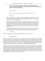
1.2 Overview
The figure below shows the overview of acceptance requirement for the AMX LATAM project.
Figure 1 : AMX Acceptance Overview – NSN proposed version
Site implementation acceptance is carried out by the implementation team after the site has been
commissioned and put on air. Once site implementation acceptance has been granted and the cluster is
deemed fit for optimization, RF cluster acceptance will begin. Here stationary and drive testing will be
carried out. Once the KPI’s are achieved for all clusters, the RF project acceptance could begin. At this
phase all tests carried out at the cluster acceptance will be done again at project level. The main
diference here is, besides the amout of points of interstes of the stationary tests, the coverage test.
Coverage verification at project level is carried out under 50% load. The other tests do not need this
additional loading. After that Provisional Acceptance (PAC) can be granted. For the Final Acceptance
(FAC) many key performance indicators need to be above the customer target during a certain stability
period.
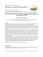
The figure below shows the relationship between all acceptance stages.
Site
Implementation
Acceptance
RF Cluster
Acceptance
RF Project
Acceptance
PAC
FAC
GUIDELINES Version Status
RF Optimization Guideline for AMX 3G Rollout 1
Consulting and System Integrations August, 27
th
2007 Revised by: Danilo Cabral
Raj Sandhu, Allan Bispo and Daniel Platero
Figure 2 : Overview of the Acceptance Stages – NSN proposed version
GUIDELINES Version Status
RF Optimization Guideline for AMX 3G Rollout 1
Consulting and System Integrations August, 27
th
2007 Revised by: Danilo Cabral
Raj Sandhu, Allan Bispo and Daniel Platero
2. RF CLUSTER ACCEPTANCE
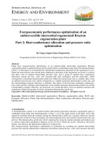
The figure below gives an overview of the RF Cluster Acceptance process.
Figure 3 : RF Cluster Acceptance Process Overview
* Only for clusters which contain 3G/2G borders sites
The RF cluster acceptance process can be grouped into 3 main sections which are the preparation
phase, optimization phase and the acceptance phase.
2.1 Preparation Phase
This phase is triggered once the rollout phase is approaching its end. The objective of this phase is to
prepare all the pre-requisites for the optimization phase. This can be broken down as below:
V Compilation of planning data
V Site Clustering
Perform Mobile Testing
Data Processing, Analysis &
Report
KPIsAchieved
Submit Report to AMX
Network Optimization &
Change Request
RF Cluster
Acceptance
Project Acceptance Phase
Y
N
Network Planning Rollout Phase
Perform Stationary Testing
Preparation Stage for Cluster
Acceptance Testing
Perform IRAT Testing*
Preparation
Phase
Optimization
Phase
Acceptance
Phase
Perform RAU Testing
GUIDELINES Version Status
RF Optimization Guideline for AMX 3G Rollout 1
Consulting and System Integrations August, 27
th
2007 Revised by: Danilo Cabral
Raj Sandhu, Allan Bispo and Daniel Platero
V Drive Routes & Site Selection for IRAT and Stationary Test
V Field Measurement Tools
V Post-processing Tools
V Parameter Consistency Check
V Alarm Monitoring
V PrxNoise Check
V Cell Availability
2.1.1 Compilation of planning data
It is essential that all the planning data be collected and saved in an organized manner in order to be
useful during the optimization phase. The required information from planning stage is:
V Technical Site Survey Report (TSSR) including panoramic pictures
V As-built Site Drawing
V Complete Site Database including Site_ID, Cell_ID, RNC_ID, BTS_ID, LAC, RAC, URA, SAC,
Antenna Type, Antenna Height, Azimuth, Tilt (Mechanical and Electrical), Scrambling Code, ATM
layer parameters, Iu parameters, IP settings etc
V Coverage plots for Loaded and Unloaded cases
V Service Area plots for the services that require optimization
2.1.2 Site Clustering
The clusters shall be defined by Nokia Siemens Networks and documented. Following criteria shall be
used in defining the cluster:
1. Each cluster shall comprise a contiguous network area of approximately 10 to 15 sites.
2. Cluster shall not be defined across RNC boundary.
2.1.3 Drive Routes and Site Selection for Stationary Test, IRAT and RAU
The drive routes for cluster acceptance will be mutually agreed by America Movil LatAm and NOKIA
SIEMENS NETWORKS. Drive Routes must cover all main avenues and large streets within in the
cluster. Main avenues should be driven in both directions as possible. The drive routes shall be selected
such that the drive route can be completed, regarding all tests scenarios mutually agreed with the
customer, in one (1) day. IRAT and stationary tests will demand one (1) additional day.
Target sites for Stationary testing, IRAT and RAU will be mutually agreed by America Movil LatAm and
NOKIA SIEMENS NETWORKS. The IRAT sites will also be known as 3G/2G Border Sites.
Ensure the following has been carried out
V The stationary test locations have been mutually agreed by America Movil LatAm and NOKIA
SIEMENS NETWORKS. This should not be more then 20% of the total sites in the cluster and
should be carried out in all sectors of the selected sites.
GUIDELINES Version Status
RF Optimization Guideline for AMX 3G Rollout 1
Consulting and System Integrations August, 27
th
2007 Revised by: Danilo Cabral
Raj Sandhu, Allan Bispo and Daniel Platero
V The IRAT and RAU drive routes have been mutually agreed by America Movil LatAm and NOKIA
SIEMENS NETWORKS.
V The mobile drive routes for cluster acceptance have been mutually agreed by America Movil LatAm
and NOKIA SIEMENS NETWORKS.
2.1.4 Field Measurement Tools
The cluster acceptance test shall consist of drive tests using Field Measurement Tools (FMT) to verify
that the call set-up and soft handovers are working properly, to detect bad quality and interference areas,
to detect unexpected lack of coverage and to test the Radio Access Bearers (RAB) that are used to
support the required services as specified in the contract. The chosen FMT should be at least be able to
measure the required data in order to calculate the KPIs for cluster acceptance. It is extremely important
to have the right FMT to carry out the RF cluster acceptance.
The FMT comprises of the following:
V Notebook equipped with the FMT software
The notebook is used to record all the measurement from the FMT. Ensure the Notebook has
specification in accordance with the FMT requirement which depends on the FMT tool used. Also the
Notebook should NOT be a NOKIA SIEMENS NETWORKS customized notebook as these normally
have encrypted hard drives and lots of security software which can affect the results of testing. This
notebook should be used dedicated for the drive or stationary testing only.
V GPS for latitude/longitude information
V UEs
These UEs should be supported by the FMT tool.
V Scanner
The purpose of using the RF scanner is to be able to scan and measure all used carriers/cells and
their corresponding DL scrambling codes. This gives the complete air interface condition of the radio
network within a selected frequency band. The results are used to identify and understand reasons
for peculiar behavior discovered during field measurements. .
The data obtained with the scanner can be useful to evaluate:
o low coverage areas
o antenna installation problems
o missing neighbors
o coverage optimization
The field measurement tool to be used is NEMO Outdoor:
GUIDELINES Version Status
RF Optimization Guideline for AMX 3G Rollout 1
Consulting and System Integrations August, 27
th
2007 Revised by: Danilo Cabral
Raj Sandhu, Allan Bispo and Daniel Platero
Figure 4: Field Measurement Tool Analysis
2.1.4.1 Field Measurement Tools Setup
For the coverage verifications in Cluster Acceptance phase, the terminal antenna must be situated
external to the vehicle, and the UE must be in idle mode. Coverage test at Project Level will be carried
out with UE in connected mode in order to obtain an UE Tx power map.
For all field QoS drives and verifications in Cluster and Project Acceptance phases, an external antenna
must not be used.
The UEs are part of the FMT. Below is showed a distribution of UE required to fullfil the most important
3G tests:
ü PS Rel 99 UE: AMR Voice Calls, PS Rel99 Data Calls, PS Rel Multi-RAB, RAU, IRAT HO and
coverage verification (in idle mode as well);
ü HSDPA UE (Cat 12): HSDPA Multi-RAB calls and Data Calls; CS video;
ü HSDPA Datacard (Cat 6): PS HSDPA Data Calls
In the Figures 6 and 9 these UEs are arranged in order to fulfill the AMX acceptance tests.
2.1.5 Post Processing Tools
The post processing tools are used for the purpose of analyzing performance related issues during the
optimization phase. It is important that the analysis tool works well with the FMT in order to be able to
capture all the events reported in the FMT. The outcome of the analysis tools will be used to generate
the RF Cluster Acceptance Report.
For the AMX project there are 3 options of post-processing tools being analyzed, as could be seen
below. Gladiator is the first option until now because fulfills all technical requirements, allows
implementing automatic analysis and reporting, and finally, is being offered by a competitive price.
The other two options, Nemo Analyzer and Actix, also fulfill the technical requirements but do not allow
any automatization. Nemo Analyzer is quite chipper than Gladiator while Actix is much more expensive.
GUIDELINES Version Status
RF Optimization Guideline for AMX 3G Rollout 1
Consulting and System Integrations August, 27
th
2007 Revised by: Danilo Cabral
Raj Sandhu, Allan Bispo and Daniel Platero
Figure 5: Post-processing Tool Analysis
2.1.6 Consistency Check
Consistency checks shall be carried out for RAN parameter to compare the actual to the planned. Also
2G and 3G neighbor bi-directional relationships shall be check for consistency between planned and
actual. This should be carried out for all sites within the cluster to be tested up till its tier 3 neighbors
before any acceptance testing.
Further to this, ATM, Iu and IP settings should also be checked to be consistent to as planned.
2.1.7 Alarm Check
The WBTS alarms shall be checked via the OSS to ensure there is no service effecting alarm. Should
there be service effecting alarms; the optimization phase shall be delayed until the alarms are cleared.
This should be carried out for all sites within the cluster to be tested up till its tier 3 neighbors before any
cluster optimization testing.
2.1.8 PrxNoise Check
The UL interference can be evaluated by looking into the PrxNoise measurements. The normal value for
this is in the range of -102 dBm to -105 dBm. Higher values would give an indication that there maybe
some issues in the cell. Possible scenarios could be external interference or wrong settings for MHA
parameters.
GUIDELINES Version Status
RF Optimization Guideline for AMX 3G Rollout 1
Consulting and System Integrations August, 27
th
2007 Revised by: Danilo Cabral
Raj Sandhu, Allan Bispo and Daniel Platero
2.1.9 Cell Availability
The cell availability of the sites gives an indication of the health of the WBTS. Prior to starting the cluster
acceptance drive testing, at least 3 days data of cell availability should be looked at to ensure that the
site has been in working condition. If there are periods of unavailability which has not been planned, then
there may be issues on the cell. This has to be investigated prior to starting the cluster optimization.
2.2 Optimization Phase
Once the mains sites defined in the target cluster have achieved all integration and site acceptance
requirement, Nokia Siemens Networks will initiate the RF cluster optimization, being a requisite to that
the sites in a cluster must not have any impeditive restriction.
The technical aspects related to the optimization activities for cluster optimizaion are available at the
chapter “Radio Optimizaiton Guide”.
The optimization phase can be divided to 4 main activities: the Stationary Testing, IRAT Testing, RAU
Testing and Mobile Testing. These are explained in more detailed below.
2.2.1 Stationary Testing
Stationary Testing will be carried out on the predefined Sites which have been mutually agreed between
Nokia Siemens Networks and America Movil LatAm. This should not be more then 20% of the total sites
in the cluster and should be carried out in all sectors of the selected sites. The figure below shows the
Stationary Test Cases to be carried out.
Stationary testing
Test
ID
Test case KPI collected Description
1 PS Rel99 RTT PS Data Latency (release 99)
- Mobile is in idle mode
- Requests PDP Context Activation
- Large ping to force DCH channel
- Pings specific IP address with 32 bytes packet
- Set 100 pings
- Repeat cycle
2
PS Rel99 DL
Throughput
PSD Throughput UE Mobile
per RB
PSD Call Set up time
- Mobile in car in idle state
- Requests PDP Context Activation
- Connects to FTP server and initiate FTP DL of 1Mbyte file
- Wait some time at the end of DL (inactivity param. dependent) for
DCH to be released
- Deactivate the PDP Context Activation
- Repeat the cycle 10 times.
3
PS Rel99 UL
Throughput
PSD Throughput UE Mobile
per RB
PSD Call Set up time
- Mobile in car in idle state
- Requests PDP Context Activation
- Connects to FTP server and initiate FTP UL of 200 kbyte file
- At the end, waits 15 sec. for DCH to be released
- Deactivate the PDP Context Activation
- Repeat the cycle 10 times.
4 PS HSDPA RTT PS Data Latency (release 5)
- Mobile is in idle mode
- Requests PDP Context Activation
- Large ping to force HS-DCH channel
- Pings specific IP address with 32 bytes packet
- Set 100 pings
- Repeat cycle
GUIDELINES Version Status
RF Optimization Guideline for AMX 3G Rollout 1
Consulting and System Integrations August, 27
th
2007 Revised by: Danilo Cabral
Raj Sandhu, Allan Bispo and Daniel Platero
5
HSDPA Call 5
code (and 15 code
when available)
PSD HSDPA Throughput UE
Mobile per RB
PSD HSDPA Call Set up time
- Mobile in car in idle state
- Requests PDP Context Activation
- Connects to FTP server and initiate FTP DL of 10Mbyte file
- Wait some time at the end of DL (inactivity param. dependent) for
HS-DCH to be released
- Deactivate the PDP Context Activation
- Repeat the cycle 10 times.
6
AMR / Rel99
MultiRAB
AMR voice CSSR during PS
64/64 call
- Large video streaming session is held (Rel99)
- AMR Voice calls are started
- A Party calls B Party and call held for 20 seconds
- A Party Terminates AMR Voice call
- Time between calls = 10 seconds
- Repeat AMR voice calls 10 times
- Stop PS session
- Repeat the whole cycle
7
AMR / Rel99
MultiRAB
PS 64/64 CSSR during AMR
Voice call
- 3G to PSTN Voice call
- Hold it indefinitely
- Wait 10 seconds
- GPRS attach and PDP Context Activation
- Pings specific IP address with 32 bytes packet 10 x
- PDP Context De-activation and GPRS Detach
- Repeat cycle 10 times
- A Party terminates AMR voice call
8
AMR / HSPA
MuliRAB
AMR voice CSSR during PS
HSPA call
- Large video streaming session is held (Rel99)
- AMR Voice calls are started
- A Party calls B Party and call held for 20 seconds
- A Party Terminates AMR Voice call
- Time between calls = 10 seconds
- Repeat AMR voice calls 10 times
- Stop PS session
- Repeat the whole cycle
9
AMR / HSPA
MultiRAB
PS HSPA CSSR during AMR
Voice call
- 3G to PSTN Voice call
- Hold it indefinitely
- Wait 10 seconds
- GPRS attach and PDP Context Activation
- Pings specific IP address with 32 bytes packet 10 x
- PDP Context De-activation and GPRS Detach
- Repeat cycle 10 times
- A Party terminates AMR voice call
10
* Short Message
Service
SMS Success Rate
SMS Delivery Time
- Mobile in Car in idle state and CS attached
- Send a SMS <= 160 bytes (characters) from the drive-test UE to the
same drive-test UE on DCH mode
- Repeat the cycle 10 times
11
* Multimedia
Message Service
MMS Success Rate
MMS Delivery Time
- Mobile in Car in idle state
- Requests PDP Context Activation
- Connect to a MMS server
- Send a MMS <= 10 Kbytes (picture) from the drive-test UE to the
same drive-test UE
- IP connection to MMS server released
- - Waits some time (inactivity param. dependent)
- Releases DCH
- Deactivates the PDP Context Activation
- Repeat the cycle 10 times
12 * WAP
WAP Failure Rate
WAP Session Establishment
Time
- Mobile in Car in idle state
- Requests PDP Context Activation
- Connect to WAP server
- Initiate WAP DL of 15Kbyte file using allocated Radio Bearer
- IP connection to WAP server released
- Waits some time (inactivity param. dependent)
- Releases DCH
- Deactivates the PDP Context Activation
- Repeat the cycle 10 times
* for SMS, MMS and WAP, the events not related to RAN will be excluded.
Table 1: Stationary Test Cases
GUIDELINES Version Status
RF Optimization Guideline for AMX 3G Rollout 1
Consulting and System Integrations August, 27
th
2007 Revised by: Danilo Cabral
Raj Sandhu, Allan Bispo and Daniel Platero
2.2.2 IRAT Testing
IRAT Testing will be carried out on a predefined route and predefined sites in the clusters that contain
3G/2G border sites. Voice calls will be make in order to evaluate the IRAT Handover Failures. It should
be carried out as functionality test at a defined 3G/2G border, repeting the process 10 times. The figure
below shows the IRAT Test Cases to be carried out.
IRAT testing
Test
ID
Test case KPI collected Description
1
Handover from
UTRAN for CS
voice service
Voice ISHO Success Rate (3G
to 2G)
- AMR continuous call (dual mode) established on the 3G side
- DT car moves toward the 2G network
- IRAT handover
- Ends call in the 2G side
- Repeat cycle.
2
Handover to
UTRAN for CS
voice service
Voice ISHO Success Rate (2G
to 3G)
- Voice continuous call (dual mode) established on the 2G side
- DT car moves toward the 3G network
- IRAT handover
- Ends call in the 3G side
- Repeat cycle.
Table 2: IRAT Test Cases
2.2.3 RAU Testing
Routing Area Update (RAU) Testing will be carried out on a border of routing areas inside of the same
SGSN footprint, for that clusters that contain different RAs, or are located on a border of RAs. RAU
Testing will be carried out for Packet Calls evaluating the intra SGSN routing area update time. It is
recommended repeating the cycle 10 times in both RA directions. The figure below shows the RAU Test
Cases to be carried out.
RAU testing
Test
ID
Test case KPI collected Description
1
PS Continuous
Call (Dual Mode)
Intra SGSN Routing Area
Update Time
- Mobile in Car in idle state, no PDP context established
- UE enters in a new Routing Area
- Requests PDP Context Activation
- UE requests Routing Area update
- UE grants a new Routing Area
- Repeat the cycle 10 times in both RA directions
Table 3: RAU Test Cases
2.2.4 Mobile Testing
Mobile testing will be carried out on the route defined to the acceptance which has mutually been agreed
between Nokia Siemens Networks and America Movil LatAm. The table below shows the Mobile test
cases to be carried out.
Mobile testing
Test
ID
Test case KPI collected description
GUIDELINES Version Status
RF Optimization Guideline for AMX 3G Rollout 1
Consulting and System Integrations August, 27
th
2007 Revised by: Danilo Cabral
Raj Sandhu, Allan Bispo and Daniel Platero
1 Idle Mode Coverage Verification - drive on the test route with UE in idle mode using an external antenna kit.
2
AMR Short Call
(3G to PSTN)
Voice CSSR (call setup
success rate)
Voice CST (call setup time)
Voice Drop Rate
Voice BLER
- 3G to PSTN Voice call
- Originating side located in the vehicle, terminating side (an answer
machine) located in the customer MSC of the test area
- A Party calls B Party and call held for 60 seconds
- A Party Terminates
- Time between calls = 10 seconds
3
Video Short Call
(3G to 3G)
CS Video CSSR (call setup
success rate)
CS Video Call Setup Elapsed
Time
Voice Drop Rate
Voice BLER
- 3G to 3G Video call
- Originating side located in the vehicle
- Terminating side located in office
- A Party calls B Party
- Call held for 60 seconds after app. level has been set up
- A Party Terminates
- Time between calls = 10 seconds
4 DL PS Rel99
DL WCDMA User Throughput
PS RAB Establishment
Success
PS RAB Drop
- Mobile in car in idle state
- Requests PDP Context Activation
- Connects to a customer FTP server and initiate FTP DL of 1Mbyte file
- Wait some time at the end of DL (inactivity param. dependent) for DCH to
be released
- Deactivate the PDP Context Activation
- Repeat the cycle 10 times.
5 UL PS Rel99
UL WCDMA User Throughput
PS RAB Establishment
Success
PS RAB Drop
- Mobile in car in idle state
- Requests PDP Context Activation
- Connects to a customer FTP server and initiate FTP UL of 200 kbyte file
- At the end, waits 15 sec. for DCH to be released
- Deactivate the PDP Context Activation
- Repeat the cycle 10 times.
6
DL HSDPA Call
5 code (and 15
code when
available)
DL HSDPA User Throughput
- Mobile in car in idle state
- Requests PDP Context Activation
- Connects to a customer FTP server and initiate FTP DL of 10Mbyte file
- Wait some time at the end of DL (inactivity param. dependent) for HS-
DCH to be released
- Deactivate the PDP Context Activation
- Repeat the cycle 10 times.
Table 4: Mobile Test Cases
2.2.5 Cluster KPI References
See appendix in the end of the document.
2.2.6 Drive-test UE Distribution – Cluster Level
In order to reduce the number of UEs to cover all measurements requested by the AMX the distribution
below is showed. Additionally, this array avoids too much load on the sites during the tests that can
jeopardize the quality of the system.
GUIDELINES Version Status
RF Optimization Guideline for AMX 3G Rollout 1
Consulting and System Integrations August, 27
th
2007 Revised by: Danilo Cabral
Raj Sandhu, Allan Bispo and Daniel Platero
Stationary Testing
Specific Area DT
Drive #1
Drive #2
Ping, Multi-RAB and ServicesISHO and RAU Testing
Coverage, Voice and
HSDPA Tests
Video and PS Rel99 Tests
UE1
PS Rel 99
DL and UL PS Rel99
AMR Continuous Call
(Dual Mode)
AMR Short Call (3G to
PSTN)
DL PS Rel99
UE1 KPIs
PS Rel 99 RTT
AMR Voice CSSR during PS 64/64 Call
PS 64/64 CSSR during AMR Voice Call
(2 hrs per point)
ISHO Succ Rate (3G to 2G)
ISHO Succ Rate (2G to 3G)
( 4 hours)
Voice CSSR
Voice CST
Voice Drop Rate
Voice BLER
DL WCDMA User Throughput
PS RAB Establishment Succ
PS RAB Drop
UE2
HSDPA Datacard
(Cat 6)
HSDPA - DL HSDPA -
UE2 KPIs
PS HSPDA RTT
(1/2 hr per point)
-
DL HSDPA User
Throughput
DL HSUPA User
Throughput
-
UE3
PS Rel 99
SMS / WAP / MMS and
PS Rel 99 Multi-RAB
PS Continuous Call (Dual
Mode)
Idle ModeUL PS Rel99
UE3 KPIs
SMS Success Rate
SMS Delivery Time
WAP Failure Rate
WAP Session Estab Time
MMS Success Rate
MMS Delivery Time
(2 hrs per point)
RAU Time (RA1 to RA2)
RAU Time (RA2 to RA1)
( 4 hours)
Coverage Verification
DL WCDMA User Throughput
PS RAB Establishment Succ
PS RAB Drop
UE4
HSDPA UE (Cat 12)
HSDPA Multi-RAB
Video Short Call (3g to 3G)
B party with auto-answering
UE4 KPIs
AMR Voice CSSR during HSPA Call
HSPA CSSR during AMR Voice Call
(2 hrs per point)
CS Video CSSR
CS Video CS Elapsed Time
CS Video Call Drop Rate
CS Video Call BLER
# UE's4133
Cluster Level
Figure 6: Drive-test UE Distribution
2.2.7 Data Processing, Analysis and Report
Collected data from each test case shall be processed and KPIs generated. The collected data and the
post-processing report must be delivered together to the analysis team. Test cases that fail to meet its
target value are then analyzed in more detail to find out its failure causes. Based on the detailed
analysis, change request shall be generated. Otherwise, if the cluster achieved all targets, the results
shall be documented in the RF Cluster Acceptance Report, and delivered for customer approval.
An optimized procedure to post-process the drive-test data is still under discussion, and this document
will be updated after the decision about this issue.
2.2.8 Change Request
The change request shall be carried out according to the process below:
GUIDELINES Version Status
RF Optimization Guideline for AMX 3G Rollout 1
Consulting and System Integrations August, 27
th
2007 Revised by: Danilo Cabral
Raj Sandhu, Allan Bispo and Daniel Platero
Figure 7: Change Request Process
Template for Change Request has not been created at this time.
Master Database to track the change request has not been created at this time.
2.3 Acceptance Phase
The acceptance phase shall commence once the entire cluster KPIs have been reached. The
acceptance phase shall involve the process of generating the RF Cluster Acceptance Report , submitting
this report for internal review and then getting the reported approved by America Movil LatAm.
After that the project level tests can be started. These tests will be detailed in the next chapter.
The RF Cluster Acceptance Report template is presented below:
KPIs Passed
Detail Analysis
Submit Change Request for
Internal Review
Perform Changes
Document changes in master
change request database
Initiate redrive to evaluate
changes
Generate KPIs
Generate Final Acceptance
Report
Y
N
Template
on the
intranet site
GUIDELINES Version Status
RF Optimization Guideline for AMX 3G Rollout 1
Consulting and System Integrations August, 27
th
2007 Revised by: Danilo Cabral
Raj Sandhu, Allan Bispo and Daniel Platero
3. RF PROJECT ACCEPTANCE
The Project Acceptance Report is the RF document that will allow America Movil LatAm to grant the
Provisional Acceptance (PAC) to Nokia Siemens Networks.
In small cities where a site division in clusters is not necessary, it will be possible to go direct to the
Project Acceptance Tests, taking in consideration all requisites described in the Cluster Acceptance
Tests. This means, in case of project tests only, all activities in the preparation phase and optimization
phase must be done considering the differences related to target KPI values and procedure tests
between cluster and project level testing.
The figure below gives an overview of the RF Project Acceptance process.
Figure 8: RF Project Acceptance * only in the 3G/2G networks border
The RF project acceptance process also can be grouped into 3 main sections, which are: the preparation
phase, optimization phase and the acceptance phase.
Perform Mobile Testing
Data Processing, Analysis &
Report
KPIsAchieved
Submit Report to AMX
Network Optimization &
Change Request
RF Project
Acceptance
3G Network Launch
Y
N
Perform Stationary Testing
Preparation Stage for Project
Acceptance Testing
Perform IRAT Testing*
Preparation
Phase
Optimization
Phase
Acceptance
Phase
Perform RAU Testing
GUIDELINES Version Status
RF Optimization Guideline for AMX 3G Rollout 1
Consulting and System Integrations August, 27
th
2007 Revised by: Danilo Cabral
Raj Sandhu, Allan Bispo and Daniel Platero
3.1 Preparation Phase
This phase is triggered once the RF cluster tests present satisfactory KPI values. The objective here is to
prepare all the pre-requisites for the optimization phase, if necessary, in the project test level. This phase
can be broken down as below:
V Compilation of planning data
Many planning data were already collected during the RF cluster activities. TSSR and As-built
remain the same, however all site database items, coverage plots and service plots must be
updated considering the entire network.
V Drive Routes & Site Selection for Stationary test, IRAT and RAU tests
The drive routes for project acceptance will be mutually agreed by America Movil LatAm and
NOKIA SIEMENS NETWORKS. Drive Routes must cover all main avenues and 70% of large
streets inside of the project area. Main avenues should be driven in both directions as possible.
Target sites for Stationary testing, IRAT and RAU tests will be mutually agreed by America Movil
LatAm and NOKIA SIEMENS NETWORKS. See details in the cluster level description.
V Field Measurement Tools
Same as in cluster level description. It’s necessary to consider for coverage tests a bunch of UEs
to generate 50% load in the system. The amount of required UE for 50% uplink Load should be
validated with field mearurements and Prxnoise from online monotoring.
V Post-processing Tools
V Parameter Consistency Check
V Alarm Monitoring
V PrxNoise check
V Cell Availability
3.2 Optimization Phase
Once at least 90% of the sites in the project area have achieved all integration and site acceptance
requirements, and the RF cluster acceptance campaign has been finished successfully, Nokia Siemens
Networks can initiate the RF project verification, being a requisite to that no impeditive restriction in any
of the 90% sites of the project area.
In case of problems to achieve the KPI for project acceptance, the appropriate optimization actions must
be taken in order to guarantee a good performance, according to the optimization process detailed in the
previous chapter.
The technical aspects related to the optimization activities for project optimizaion are available at the
chapter “Radio Optimizaiton Guide”.
Stationary testing and RAU testing can be removing from this phase since already carried out on cluster
level phase. Otherwise, if the rollout goes direct to the project level, these two tests must be considered.
See cluster level description.
GUIDELINES Version Status
RF Optimization Guideline for AMX 3G Rollout 1
Consulting and System Integrations August, 27
th
2007 Revised by: Danilo Cabral
Raj Sandhu, Allan Bispo and Daniel Platero
IRAT testing and Mobile testing have to be carried out following the strategy of the detailed in the cluster
level activities. Some differences are explained below.
3.2.1 IRAT Testing
The test is the same as in cluster level; however the 3G/2G border sites and the IRAT drive-test route
will be mutually agreed by Nokia Siemens Networks and America Movil LatAm in a project level basis.
3.2.2 Mobile Testing
The measurements are equal to that ones in the cluster level, therfore the strategy remains the same as
showed in the previous chapter.
Mobile testing will be carried out on the predefined route which has been mutually agreed by Nokia
Siemens Networks and America Movil LatAm. The table below shows the delta for the Mobile test case.
The others tests are detailed in the cluster table above.
The main differences are related to KPI values, basically CSSR, and the coverage tests. This last one
implies in a special approach because will be need to generate 50% load during the coverage
verification.
Mobile testing – delta from the cluster testing
Test
ID
Test case KPI collected description
1 Connected Mode Coverage Verification
Drive on the test route with UE in connedted mode using an external
antenna, while a bunch of UEs, holding simultaneous CS video calls, will
generate 50% load from the drive-test vehicle.
Table 5: Coverage Test in project level
3.2.3 Cluster KPI References
See appendix in the end of the document.
3.2.4 Drive-test UE Distribution – Project Level
In order to reduce the number of UEs to cover all measurements requested by the AMX the distribution
below is showed. Additionally, this array avoids too much load on the sites during the tests that can
jeopardize the quality of the system.
GUIDELINES Version Status
RF Optimization Guideline for AMX 3G Rollout 1
Consulting and System Integrations August, 27
th
2007 Revised by: Danilo Cabral
Raj Sandhu, Allan Bispo and Daniel Platero
Stationary Testing
Specific Area DT
Drive #1
Drive #2
Drive #3
Ping, Multi-RAB and ServicesISHO and RAU TestingCoverage Testing
Coverage, Voice and
HSDPA Tests
Video and PS Rel99 Tests
UE1
PS Rel 99
DL and UL PS Rel99
AMR Continuous Call
(Dual Mode)
AMR Continuous Call
AMR Short Call (3G to
PSTN)
DL PS Rel99
UE1 KPIs
PS Rel 99 RTT
AMR Voice CSSR during PS 64/64 Call
PS 64/64 CSSR during AMR Voice Call
(2 hrs per point)
ISHO Succ Rate (3G to 2G)
ISHO Succ Rate (2G to 3G)
( 4 hours)
Coverage Verification
+
(N UE’s for 50% load
emulation)
Voice CSSR
Voice CST
Voice Drop Rate
Voice BLER
DL WCDMA User Throughput
PS RAB Establishment Succ
PS RAB Drop
UE2
HSDPA Datacard
(Cat 6)
HSDPA
DL HSDPA
-
UE2 KPIs
PS HSPDA RTT
(1/2 hr per point)
DL HSDPA User Throughput
DL HSUPA User Throughput
-
UE3
PS Rel 99
SMS / WAP / MMS and
PS Rel 99 Multi-RAB
PS Continuous Call (Dual
Mode)
-Idle ModeUL PS Rel99
UE3 KPIs
SMS Success Rate
SMS Delivery Time
WAP Failure Rate
WAP Session Estab Time
MMS Success Rate
MMS Delivery Time
(2 hrs per point)
RAU Time (RA1 to RA2)
RAU Time (RA2 to RA1)
( 4 hours)
-Coverage Verification
DL WCDMA User Throughput
PS RAB Establishment Succ
PS RAB Drop
UE4
HSDPA UE (Cat 12)
HSDPA Multi-RAB
Video Short Call (3g to 3G)
B party with auto-answering
UE4 KPIs
AMR Voice CSSR during HSPA Call
HSPA CSSR during AMR Voice Call
(2 hrs per point)
CS Video CSSR
CS Video CS Elapsed Time
CS Video Call Drop Rate
CS Video Call BLER
# UE's41133
Project Level
Figure 9: Drive-test UE Distribution in Project Level
3.2.5 Data Processing, Analysis and Report
Same procedure adopted in cluster level. If the project achieved all targets, the results shall be
documented in the RF Project Acceptance Report, and delivered for customer approval.
An optimized procedure to post-process the drive-test data is still under discussion, and this document
will be updated after the decision about this issue.
3.2.6 Change Request
See flow in the previous chapter.
3.3 Acceptance Phase
The acceptance phase shall commence once the entire project KPIs have been reached. The
acceptance phase shall involve the process of generating the RF Project Acceptance Report , submitting
this report for internal review and then getting the reported approved by America Movil LatAm.
After that the Provisional Acceptance (PAC) can be requested by Nokia Siemens Networks as showed in
the overview of the figure 2.
The RF Project Acceptance Report template is presented below:
Template
on the
intranet site
GUIDELINES Version Status
RF Optimization Guideline for AMX 3G Rollout 1
Consulting and System Integrations August, 27
th
2007 Revised by: Danilo Cabral
Raj Sandhu, Allan Bispo and Daniel Platero
4. RADIO OPTIMIZATION GUIDE
This chapter gives an overview of the common pre-launch optimization activities carried out. Here you
can find information about Network Initial Tuning, OSS KPI optimization and Parameters optimization.
It’s also recommended to check the last release of the following documents: WCDMA RAN Key
Performance Indicators, Optimizing WCDMA RAN and Interdependencies of Telecom Features (all from
system documentation) and RANPAR, RANOP1 and RANOP2 courses. This document is based on
RAS05.1.
This chapter shows the main performance issues, how to identify then, what could be done to fix it and
the related parameters to optimize.
The Performance Issues are organized in two main topics:
- Initial Tuning Issues
- Optimization Issues
4.1 Initial Tuning
4.1.1 Definitions
Initial Tuning is the activity of optimization related to Pre-Launch of a network. It includes
finding and solving any discrepancies between the design and the real network. It’s mainly
related to site installation problems, database checks, coverage problems and handover /
neighbour list problems.
In W-CDMA there is no clear distinction between initial tuning and optimization. Arbitrarily it
can be said, that semi-static parameters i.e. parameters that will not vary a lot when traffic
is loading the network can be assessed and adjusted at the initial stages of the network just
before launch (initial tuning). However virtually all parameters associated with the
performance of a W-CDMA network are affected by system load thus should be optimized
when the network is up and running and a sufficient number of “live” network
measurements is available.
Initial Tuning could be performed in four steps:
1. Collection of information about the network planning (RF threshold and targets) and
definition of test areas & routes of drive tests
2. Performing drive tests in existing network, collecting data of network performance by use
of RF UMTS Field Measurement Tools
3. Evaluation of measurement results, Analysis and reporting
4. Final tuning and optimization of W-CDMA network by evaluation of test measurement
results (coverage optimization, parameter adjusting)
GUIDELINES Version Status
RF Optimization Guideline for AMX 3G Rollout 1
Consulting and System Integrations August, 27
th
2007 Revised by: Danilo Cabral
Raj Sandhu, Allan Bispo and Daniel Platero
4.1.2 Initial Tuning Procedure – Overview
Initial tuning is a process from the very beginning of radio network planning to an iterative
process of adjusting specific cells within network in active mode, in order to receive an
optimal tuned W-CDMA network.
Figure 10: Initial Tuning Procedure
4.1.2.1 Preparation Phase
This is the starting phase. It is very important to define the following items for each desired
service, and for all possible types of environment (dense urban, urban, suburban, rural and
road):
ü Link budget for dedicated channels (incl. a certain cell load)
ü Link budget for CPICH (Common Pilot Channel)
ü Minimum required RSCP level (Received Signal Code Power)
ü Minimum required Ec/Io including a margin for network load (Received Energy per
Chip divided by the Power Density in the band)
ü Maximum allowable pathloss for up- and downlink
These values are taken as reference during the field activities and post-processing. Thus it
is essential to jointly define the mentioned figures and share all the relevant data (between
Radio Network Planning and Initial Tuning Team).
Preparation Phase
•Link Budget definitions
•Required RF targets
•Services and Areas definitions
•Complete Site / RNC Database
•Routes Definition
•Technical Site Survey Report (TSSR)
•As-built Site Drawing
•Coverage plots
•Service Area plots
Post-Processing & Reporting
•Route post-processing
•Maps & graph preparation
•Generation of reports and statistics
Analysis and Definition of Changes
•Coverage Analysis
•Pilot Pollution
•Missing Neighbor
•Neighbor List Optimization
•External Interference Verification
•HW problems Identification
•RF Parameters Tuning
•Changes Request Elaboration
TUNED
NETWORK
NETWORK
IMPLEMENTATION
Measurement
Collection
•Drive-test