Kiến trúc phần mềm Radio P3 pdf
Bạn đang xem bản rút gọn của tài liệu. Xem và tải ngay bản đầy đủ của tài liệu tại đây (1.46 MB, 39 trang )
Softwar e Radio Arc hitecture: Object-Oriented Approac hes to Wireless Systems Engineering
Joseph Mitola III
Copyright
c
!2000 John Wiley & Sons, Inc.
ISBNs: 0-471-38492-5 (Hardback); 0-471-21664-X (Electronic)
3
The Radio Spectrum a nd RF
Environment
Radio is the penultimate medium for mobile communications, but it has also
been used for many fixed-site applications such as AM/FM broadcast, satellite
trunking, point-to-point microwave telephony, and digital TV. Although there
are radio applications in very low frequencies (VLF) and extremely low fre-
quencies (ELF), these bands require extensive fixed-site infrastructure w hose
size and cost is dominated by the mile-long antennas and megawatt-power
handling requirements. SDR insertion opportunities in these bands are lim-
ited. Therefore, this text is concerned w ith the bands in which there are major
economic opportunities for software-radio technology insertion: HF through
extremely high frequencies (EHF).
I. RF SIGNAL SPACE
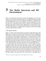
Figure 3-1 shows how terrestrial radio uses cluster in RF signal space. This
figure shows the notional clusters of the significant band/mode combinations
addressed by software radio technology. This space is the two-dimensional
cross product of radio frequency and duty cycle.
17
Since coherent bandwidth
is proportional to carrier frequency, the figure is also labeled in terms of nom-
inal instantaneous bandwidth. A QPSK encoded T- or E-carrier signal is on
continuously for a duty cycle of 1.0. Low-duty-cycle modes such as burst com-
munications and ultra-wideband (UWB) have high peak power as suggested
by the additional label on the axis. This is not an exact correspondence, but it
shows a trend related to the thermal properties of power-handling devices.
The PTT modes have the duty cycle of voice, which is about 25% dur-
ing speech epochs. Given conversational pauses, a voice channel is typically
occupied less than 10% of the time. The busiest military voice channels are
occupied not more than 40% in a full duplex channel such as the typical LVHF
military bands. On the other hand, troposcatter radios have high peak power
and unity duty cycle. The tropo cluster was positioned to show the high peak
power. HF communications may also have high power, but the duty cycle is
typically that of voice or low-speed data. As the label on the right side of
the figure suggests, the greater the ratio of peak power to minimum power,
17
Duty cycle is the ratio of signal on-time to the elapsed time of an epoch.
73
74
THE RADIO SPECTRUM AND RF ENVIRONMENT
Figure 3-1
Communications modes cluster in RF signal space.
the greater the dynamic range requirements on the ADC in the receiver. Since
there is no wideband R F or ADC that can encompass all RF with the full
dynamic range, designs historically have addressed a single mode. The SDR
addresses a few clusters, while the software-radio architecture embraces mi-
gration toward the entire signal space. It is therefore essential to consider each
of these clusters in detail.
A. Overview of Radi o Bands and Modes
This section p rovides an overview of radio bands and modes. HF commu-
nications consist primarily of voice, narrowband data, and Morse code,
some of which is generated by machine and some of which is generated
manually. The literature also presents successful research in the use of
wideband spread spectrum at HF, including thousands-of-chips-per-bit and
millions-of-chips-per-second (MHz) [119]. In addition, HF radar uses
direct-sequence spread spectrum in a frequency-hopped pulsed signal struc-
ture. Neither of these relatively exotic waveforms are s hown in order to
focus the figure on the waveforms likely to be encountered in software
radios.
LVHF includes spectrum allocated to military users who traditionally have
employed half-duplex PTT analog frequency modulated (FM) single-frequen-
cy voice modes. Military LVHF also includes many FH spread-spectrum ra-
dios. In addition, the literature describes burst signal structures such as meteor
burst. These radios transmit data at relatively high data rates for tens to hun-
dreds of milliseconds with high instantaneous data rates, a low duty cycle, and
therefore relatively low average data rate.
RF SIGNAL SPACE
75
The LVHF and VHF frequency bands also support frequency division
multiplexed (FDM) multichannel radios with typically 4 to 12 radio relay
telephony channels for military users. These may also employ pulse code
modulation (PCM) for digital telephony as alternate modes of an FDM/PCM
dual-mode radio. The FDM mode provides compatibility with older equip-
ment, but the improved quality of PCM makes it the mode of choice for
most applications. For long-haul telephony relay, the FDM or PCM signals
may use very high-power propagation modes like troposcatter. Thus, the
figure shows a high-power cluster for “relay and tropo.” These high
power modes use constant-duty-cycle FDM and PCM waveforms, an excep-
tion to the pattern that higher peak power typically implies lower duty
cycle.
Mobile cellular radio (MCR) operates in frequency allocations between
400 MHz and 2.5 GHz, with clusters at 900 and 1800 MHz. There are similar
radio services such as special mobile radio (SMR) as low as 40 M Hz. The
Instrumentation Scientific and Medical (ISM) bands at 2 and 5 GHz support
personal communications systems (PCS) and RF LANs. MCR has become
popular worldwide for rapid deployment of business and residential telephony
in developing economies. MCR avoids the burial of fiber or cable for rapid
build-out. Wireless local loop (WLL) has most features of MCR with reduced
handset mobility [75].
The military employs specialized radar transponders for the Identification
of Friends or Foes (IFF) and for other Integrated Communications, Navigation,
and Identification Architecture (ICNIA) functions including tactical data links
(e.g., remote radar plan position indicator displays) [120]. Distance measure-
ment equipment (DME) and tactical air navigation (TACAN) also fall into this
category of typically moderate duty cycle and moderate to high instantaneous
data rate m odes. Software r adios for the military often must monitor multiple
bands and modes for flight safety reasons. They typically require multiple
navigation, IFF, and command-and-control communications for redundancy.
These modes fall in a cluster of pulsed and lower-duty-cycle/high-peak-power
signals.
The Synchronous Optical Network (SONET) [5] carries most backbone
telephony in developed n ations. Such fibers may be disrupted as much as six
times per year per hundred miles of fiber (this rate was an industry rule of
thumb in the United States in the early to mid-1990s). Consequently, SONET-
compatible high-capacity microwave radios were developed with interoperable
data rates of 155 (OC-3) and 622 Mbps (OC-12). Deployments in some in-
frastructures protect fiber paths, while others cross obstacles where it may
be difficult, expensive or impossible to lay fiber, such as extreme terrain and
bodies of water. Interoperation with SONET networks connects SDR nodes
to the larger PSTN.
Finally, Figure 3-1 shows how radar signals typically emit the highest ra-
diated power and employ the lowest duty cycles of any cluster in RF signal
space. Impulse radar can create high-resolution maps of hidden objects (e.g.,
76
THE RADIO SPECTRUM AND RF ENVIRONMENT
by penetrating walls). UWB communications use the same subnanosecond
pulse technology operating at baseband. Time Domain Corporation’s UWB
system, for example, encodes data into an impulse train with an average of
40 million pulses per second (PPS). Since UWB communications employ
subnanosecond pulses not readily synthesized with current-generation SDR
hardware (e.g., FPGAs and DSP chips), UWB is not a focus of SDR stan-
dardization. On the other hand, as the underlying digital technology continues
to evolve into clock rates over 1 GHz, UWB will ultimately migrate into the
domain of the SDR. At today’s rate of technology development, UWB will be
accessible with SDR technology within 10 years. With the near-term excep-
tion of UWB, any of the bands and modes of Figure 3-1 may be implemented
using the SDR techniques described in this text.
When used together a mix of modes across multiple radio bands provides
a new dimension in QoS, reliability, and efficiency in the employment of the
radio spectrum. After considering the top-level characteristics of these bands
that are relevant to software-radio architecture, each band is considered in
detail.
B. Dynamic Range-Bandwidth Product
As mentioned earlier, the right side of Figure 3-1 is labeled “ADC Dynamic
Range.” This highlights the fact that the ratio of lowest to highest power signal
in the receiver (total dynamic range) drives the requirements the ADC. As one
accesses successively larger chunks of bandwidth, the sampling rate of the
ADC must increase to at least 2.0 times the maximum frequency component
(
f
max
) to satisfy the Nyquist criterion. Sound engineering principles require
sampling at 2.5
f
max
. In addition, the larger bandwidths are needed to service
multiple subscribers with a single ADC. Narrowband analog recei vers employ
AGC to accommodate m any decades of difference in recei ved signal strength
from a high-power nearby subscriber to the weakest, most distant subscriber.
Analog receivers also filter high-power interference out of the analog signal-
processing band.
The near–far ratio (NFR) is the ratio of the highest-power (presumably
nearby) signal to the weakest (presumably most distant) signal. This ratio is
90 dB in GSM. Given a requirement for a 15 dB SNR for BER appropriate
to the required QoS, the total dynamic range is at least 105 dB. Any in-
band interference can raise this total dynamic range further. As the service
bandwidth increases, the p robability increases that subscribers and interferers
with much higher power will be present in the receiver’s RF band. In an
HF band from 3 to 30 MHz, for example, the dynamic range of received
signals is typically between 120 and 130 dBc (dB relative to full scale). Since
ADCs nominally provide 6 dB of dynamic range per bit, one would need an
ADC with 130
=
6=
"
22 bits (at least) to service all potential HF subscribers.
Contemporary ADCs with the necessary 70 M samples per second (Msps)
sampling rates have only 14 (84 dB) of dynamic range. Thus, it is impossible to
HF BAND COMMUNICATIONS MODES
77
access the entire HF band with today’s ADC (and DAC) technology. N ear-term
implementations therefore m ust tailor the architecture by s tructuring access to
each band so that the communications objectives of SDR applications are met
within the numerous constraints of available technology, including the ADC.
This tailoring process requires an understanding of the HF and other modes
presented below.
To extend this reasoning further, a multiband multimode radio such as
SPEAKeasy was intended to service HF, VHF, and UHF military bands (from
2 MHz to 2 GHz). This means both sustaining the high dynamic range of HF
and sampling the 2 GHz bandwidth, requiring a 5 GHz sample rate which is
96.9 dB-Hz. A useful
figure of merit
,
F
, for uniform digital sampling using
ADCs and DACs is:
F
= Dynamic Range (dBc) + Sampling Rate (dB/Hz)
SPEAKeasy would require
F
= 226
:
9dB/Hz(96
:
9 dB/Hz + 130 dBc), well
beyond the state of the art of 140 to 160 dBc/Hz. Although we are mak-
ing progress in ADC technology, practical engineering implementations of
software radios avoid the frontal assault of a single ADC. Instead, the art
and science of software radio systems engineering includes the partitioning
of the total service bandwidth (e.g., from 2 MHz to 2 GHz) into multiple
parallel RF bands. These are partitioned further into multiple parallel service
bands (ADC/DAC channels). Each subband would have filtering, AGC, and
digital signal processing that match the available ADC technology. The RF
signal-space suggests regions within which a single ADC may provide effec-
tive sampling. The subbands and modes developed subsequently further refine
these regions.
II. HF BAND COMMUNICATIONS MODES
HF extends from 3 to 30 MHz according to international agreement. The def-
inition of ITU frequency bands is taken from [5]. The length o f a full-
cycle radio wave in these bands is 100 meters at 3 MHz and 10 meters at
30 MHz, with linear variation between these extremes according to
c
=
f
#
¸
,
where
c
is the speed of light,
¸
is the wavelength, and
f
is the radio frequen-
cy. Wavelengths determine the physical sizes of resonant antennas. Anten-
nas resonate well across bandwidths that are less than 10% of the carrier
frequency. To cover a full HF band using such a resonant structure would
require about ten such antennas. The alternatives are to physically tune the
narrowband antennas to operate on a specific subband, or to use a wide-
band antenna to access more of the band at once. A multiband radio there-
fore could employ a mix of wideband and tunable narrowband antennas
drawn from the conventional antennas described in this and subsequent sec-
tions.
78
THE RADIO SPECTRUM AND RF ENVIRONMENT
Figure 3-2
The HF communications band.
A. HF Propagation
As Figure 3-2 suggests, HF radio waves are usually reflected from the iono-
sphere, resulting in communications beyond line of sight (LOS). The iono-
sphere has several layers from w hich the waves may reflect. These are identi-
fied as the D, E, and F layers in order of increasing altitude. Two or more such
skywaves may be received in what is called
multimode propagation
.These
waves will add (as complex vectors) at the receiver resulting in phase and
amplitude variability. The time differences between two reflected waves (HF
propagation modes) will be about 1 ns per foot of altitude separation. Since
the reflecting layers may be from 1 to 10,000 miles apart, this equates to 1 to
10 ms of delay-spread. In addition, the ionosphere and fixed transm itters on
the earth are typically approaching or receding, imparting Doppler shift onto
the RF carrier. Since the layers of the ionosphere may be moving in different
directions, the Doppler spread at HF is large, typically 5 Hz.
If the RF carrier is too low or too high, it will pass through the ionosphere.
Beyond LOS, reflections from the ionosphere are only possible on radio fre-
quencies between the least usable frequency (LUF) and the maximum usable
frequency (MUF). Specific combinations of RF and antenna configuration can
result in near vertically incident (NVI) propagation in which the waves reflect-
ing from the ionosphere propagate only a few tens of miles. NVI is useful in
mountainous areas for communications between subscribers in adjacent val-
leys, for example. In addition, HF will reflect from water and from some land-
masses, enabling multihop communications (ionosphere–water–ionosphere–
land).
HF BAND COMMUNICATIONS MODES
79
B. HF Air Interface Modes
Morse code has been used since the 1800s for ship-to-shore and transoceanic
communications. Machine-generated Morse code became popular with the
emergence of microprocessors in the mid-1980s. PC-based software readily
translates text into Morse. Voice transmission at HF uses amplitude modu-
lation (AM) to accommodate the limited bandwidth of the HF channel. The
simple double side band (DSB) AM creates two mirror-image replicas of the
voice waveform—one above and one below the carrier, using twice the band-
width required for the information content. Upper side band (USB) filters
the lower of these two voice bands, suppressing any residual carrier. Lower
side band (LSB) is the converse of USB. Vestigial side band (VSB) allows
a small component of carrier to be transmitted, simplifying carrier r ecovery
in the recei ver. Each of these modes is used in HF communications. Voice
intelligibility requires only 3 to 4 kHz for the principal formants (sinusoidal
information-bearing components of the speech waveform). Consequently, each
of these modes may be digitally implemented with an ADC rate of typically
10 to 25 kHz using commodity DSP chips with modest processing power (10
to 25 million instructions per second—MIPS). Thus, the speech-processing
niche was one of the first commercial applications of ADCs and DSPs.
Morse code might be thought of as an on-off-keyed (OOK) data mode
with the channel code information carried in the duration (pulse width) of the
channel waveform—Morse
dits
are three to four t imes shorter than
daa’s
.Be-
cause of the relatively low rate at which p eople can compose and send Morse
code, it occupies a bandwidth approximately 5 Hz. This yields a plethora of
such narrowband signals packed into the very busy HF bands. Other com-
mon HF data modes include frequency shift keying (FSK). The FSK channel
code consists of
mark
or
space
, corresponding to a negative or positive fre-
quency shift, respectively. The frequency shift may be as small as a few tens
of Hz. Data rates ranging up to 1200 bits per second require FSK shifts of
several hundred Hz. An FSK channel symbol is also called a
baud
.Iten-
codes one bit of information. During very short time intervals (from a few
milliseconds to a few tenths of a second), the ionospheric transfer function
is approximately constant. Higher data rates (e.g., 10 to 40 kbps) may be
used for such short intervals to
burst
small amounts of data over long dis-
tances using FSK modems. Both standard and burst FSK waveforms can be
implemented using commodity DSP chips and low-speed/high-dynamic-range
ADCs. HF Automatic Link Establishment (ALE) equipment [121]
18
probes
the propagation path in a pre-arranged sequence to identify good frequencies
on which to communicate. The ALE signals include “chirp” waveforms that
linearly sweep the RF channel so that the receiver can estimate the channel
transfer function. The two ends of the link negotiate choice of RF based on
reception quality.
18
The examples of military communications equipment appearing in this chapter are from [121].
80
THE RADIO SPECTRUM AND RF ENVIRONMENT
TABLE 3-1 Software Radio Applications Parameters—Baseband and HF
Software Radio Application Sampling Rate
(
f
s
)
Dynamic Range (dB)
HF Baseband .5–8 kHz 24–64
Modems 8–32 kHz 48–64
Music 20–100 kHz 60–96
HF-IF .2–10 MHz 72–120
HF RF 75 MHz 130
The research literature also describes a long-haul HF telecommunication
system using direct-sequence s pread spectrum to achie ve a data rate of 100
kbps via a 10 MHz spreading sequence [119]. Low grazing angle, nearly
optimal choice of transmit and receive frequency, and l ocation and other spe-
cialized factors contributed to the success of this experiment, which appears
infeasible for general HF communications. The serial modem [122] delivers
1200 to 2400 baud data on HF channels with high reliability. Recently, t he
SiCom Viper [424] direct-sequence spread-spectrum radio has demonstrated
data rates of 19.2 kbps and 56 kbps over skywave HF links on a routine ba-
sis by employing cyclostationary techniques in t he receiver. This 1 to 2 M Hz
spread-spectrum signal has an instantaneous SINR of about
$
50 dB, which it
overcomes with processing gain.
The software radio parameters of HF sampling rate and dynamic range
depend on the point in the system at which the ADC/DAC operates from
baseband through IF to RF, as illustrated in Table 3-1.
C. HF Services and Pro ducts
Amateur radio (ham), commercial broadcast, aeronautical mobile, amateur
satellite, and timing/frequency standards are provided at HF as outlined in Fig-
ure 3-2. HF antennas and power amplifiers often dominate the size, weight,
and power of HF radio systems. Antennas matched to HF wavelengths are
large—some research antennas extend for over a kilometer. M ilitary applica-
tions employ circularly disposed array antennas for long-haul communications
and location finding using triangulation. Reliable long-haul communications
is also possible using small log-periodic antennas (e.g., 20
%
25 meters hor-
izontally mounted on a 50 or 100 ft mast). W h ip antennas 8 to 15 ft long
may also be inductively loaded to match HF wavelengths. And 2 to 10 meter
loop antennas measure direction of arrival. Although software radios cannot
change the laws of physics that cause HF antennas to be large, they can en-
hance signals received using smaller, less optimally tuned antennas to achieve
quality approaching that of the larger antennas.
Mercury Talk [121] exemplifies the relatively short-range, low-power HF
radios. With 2 watts of output power, this radio can close a voice link on a
10 km path. With its 3.5 watt output, it can close a Morse code link over a
LOW-BAND NOISE AND INTERFERENCE
81
Figure 3-3
Radio noise and incidental interference.
160 km path. Thomson CSF of France makes the TRC331, another portable
HF radio weighing less than 10 kg. Figure 3-2 lists additional narrowband
communications standards such radios meet for military interoperability.
III. LO W-B AND NOISE AND INTERFERENCE
As illustrated in Figure 3-3 [from 5, p. 34-7], the lower radio bands—HF, VHF,
and lower UHF—include significant sources of radio noise and interference.
The incidental and unavoidable interference includes automobile ignitions,
microwave ovens, power distribution systems, gaps in electric motors, and the
like. Cellular bands are dominated by intentional interference introduced by
other cellular users occupying the RF channel in distant cells. Unavoidable
interference results when tens to hundreds of thousands of military personnel
use their LVHF radios at the same time. Thus, high levels of interference
characterize these congested low bands.
The noise/interference levels are defined with respect to thermal noise:
P
n
=
kTB
where
k
is Boltzmann’s constant,
T
is the system temperature (
T
0
is the refer-
ence temperature of 273 K elvin), and
B
is the bandwidth (e.g., per Hz).
82
THE RADIO SPECTRUM AND RF ENVIRONMENT
Figure 3-4
The LVHF communications band.
In the microwave bands above 1 GHz this thermal noise
19
is a good approx-
imation of the noise background. In urban areas, however, incidental urban
interference dominates thermal noise until about 5 GHz. In the lower bands,
atmospheric noise arises from the reception of lightning-induced electrical
spikes from thunderstorms, etc. halfway around the world. Consequently, this
noise component is much stronger in summer than in winter as illustrated in
the figure. In addition, this noise has a large variance. The short-term (1 ms)
narrowband (1 kHz) noise background varies at a rate of a few dB p er sec-
ond over a range of from 10 to 30 dB, depending on the latitude, time of the
year, and sunspot cycle. High-quality HF receivers track this noise background
independently in each subscriber channel.
IV. LOW VHF (LVHF) BAND C OMMUNICATIONS MODES
The LVHF band from 28 to 88 MHz has traditionally been the band of ground
armies because of the robust propagation offered among ground-based sub-
scribers in rugged terrain. Amateur radio and the U.S. citizens’ band also use
LVHF. The upper edge of this band is defined by the commercial broadcast
band from 88 to 108 MHz. Wavelengths from 10.7 to 3.4 meters admit smaller
antennas than HF, with a
1
4
wave dipole having a length of 3 to 10 feet, as
summarized in Figure 3-4. Historically, LVHF military users have employed
19
Because of the equation, thermal noise is sometimes called kTB noise.
LOW VHF (LVHF) BAND COMMUNICATIONS MODES
83
single-channel half-duplex PTT AM and FM modes. The commercial success
of Racal’s
!
R
Jaguar frequency-hopped radio with its digital vocoding and dig-
ital air interface resulted in a proliferation of FH modes for military users
during the late 1980s.
A. LVHF Propagation
Although LVHF frequencies do not reflect from the ionosphere with the re-
liability of HF, it is possible t o scatter these wa ves from the lower D layer
of the ionosphere. D layer scatter at 30–60 MHz with a bandwidth of less
than 10 kHz often has only about 8.5 dB greater loss than LOS propagation.
In addition, in LVHF, propagation beyond geometric LOS is common due to
tropospheric refraction. Since the atmosphere is denser at lower altitudes, the
speed of light is less near the ground than at higher altitudes. Since typical
LVHF whip antennas provide an omnidirectional radiation pattern with rela-
tively large vertical extent, the waves propagate across significant differences
in index of refraction. Therefore, the waves emitted just above the geometric
grazing angle propagate beyond the geometric LOS, having been bent down
as they traverse the path. This effect can be modeled as an increase in the
effective radius of the earth. The approximation of radio horizon is given by:
R
=
!
4
Kh=
2
Range is in miles.
K
is the effective radius of the earth, and
h
is the alti-
tude of the transmitter in f eet.
K
, the effective earth radius, i s defined experi-
mentally.
K
= 1 defines geometric LOS propagation. Typically
K
=4
=
3in
temperate climates. But
K
may range from 1/3 to 3 as a function of climate
and weather. At night, particularly in subtropical climates, LVHF waves may
propagate by a ducting phenomenon in which the refractive index of the at-
mosphere exhibits an inv ersion (air density increases with increasing altitude
instead of decreasing). Ducting can extend the range of LVHF two hundred
miles or more beyond LOS. Ground-to-air radios also experience skywave
multipath scattered from the D layer or refracted through tropospheric ducts.
1. Diffraction
Knife-edge diffraction is a wave phenomenon in which waves
bend around sharp obstructions as if the entire wavefront above the obstacle
consisted of point sources. These point sources induce an interference pattern
of reinforcement (waves on the average in phase) and cancellation (waves on
the average 180 degrees out of phase) called the Fresnel zones. A receiver
in the Fresnel zones e xperiences alternating strong and weak signals as the
receiver moves through multiples of a wavelength. VHF radios may maintain
reception continuity across Fresnel zones using diversity in space (e.g., multi-
ple antennas) and frequency (e.g., slow frequency hopping) with error control
coding.
84
THE RADIO SPECTRUM AND RF ENVIRONMENT
2. Reflections from Meteor Trails
Each minute a dozen meteors penetrate
the earth’s atmosphere, where they burn up. This creates trails of ionized g as
from which radio waves may be reflected. Meteor burst communications use
trails that endure for periods of 10 milliseconds to over a second. Meteor burst
in the 50 to 80 MHz RF ranges will propagate short bursts of communications
over distances of from 600 to 1300 km with radiated power of about 1 kW and
with bandwidths of up to 100 kHz. With directional antennas, meteor burst
provides a relatively secure way of exchanging low-volume command-and-
control data over ranges significantly beyond LOS. LVHF, like HF, may also
be propagated via ground wave over short ranges (e.g., 10 km). Ground wave
generally suffers large attenuation, with a path exponent of 2.5 to 4. That is,
instead of path loss proportional to 1
=R
2
, the path loss will be proportional to
1
=R
2
:
5
to 1
=R
4
.
B. Single-Channel-per-Carrier LVHF Air Interface Modes
AM (DSB, USB, LSB, and VSB) and analog-modulated FM voice are com-
mon at LVHF. FSK and phase shift keying (PSK) are common data modes.
Simple PSK formats such as binary (BPSK) and quaternary PSK (QPSK) offer
reliable data service at LVHF from 1.2 kbps to about 10 kbps within the co-
herence bandwidth of LVHF. The use of digital vocoding and private networks
(e.g., TETRA [123]) is increasing in these bands. The analog modes arose in
the 1960s. Signal processing was limited to analog frequency translation, filter-
ing, automatic gain control, and simple control circuits. In these modes, each
subscriber has a unique RF carrier. Such single-channel-per-carrier (SCPC)
modes have historically been preferred by ground-based military forces for
squad-level manpack and individual vehicular radios. Contemporary LVHF
military radios usually employ FH for TRANSEC. LVHF propagates well in
rugged terrain since the waves penetrate vegetation and reflect, refract, and
diffract over and around obstacles. This fills in low-lying areas w here higher-
frequency waves would not penetrate surrounding obstacles.
C. LVHF Spread-Spectrum Air Interfaces
Spread-spectrum modes include FH, DSSS, and hopped-spread hybrids. Some
FH radios hop over subbands of LV HF, employing 1 to 6 MHz hopping bands.
Others provide the full 60 MHz hopping agility from 2 8 to 88 MHz. T he nar-
rower hop bandwidths may be implemented digitally via SDR techniques (e.g.,
using a fixed tuned medium bandwidth RF chain and a 6 MHz ADC/DAC).
The 60 MHz hop bandwidths are not accessible using fixed tuned RF, but
instead the hops must be heterodyned to a common IF using a fast tuned syn-
thesizer (or two). As ADC and DAC bandwidths and dynamic range continue
to improve, SDR radio techniques may extend to wider hop-bandwidths.
The FH r adios are typically vocoded. The s peech waveform is represented
digitally using a vocal tract model such as Linear Predictive Coding (LPC).
LOW VHF (LVHF) BAND COMMUNICATIONS MODES
85
LPC-10, for example, was a standard 1200-bit-per-second voice codec used
throughout the 1970s and early 1980s. More complex waveforms based on
subband coding [124] and adaptive LPC were implemented in DSP chips
in the middle to late 1980s. This led to other voice codecs such as Vector
Excited Linear Prediction (VELP) and Codebook Excited Linear Prediction
(CELP) with better perceptual properties. In addition, many LVHF radios em-
ploy slow FH (
<
100 hops per second), so that sufficient bits are available per
hop dwell to reconstruct a voice epoch. Some coded vocal tract parameters
require enhanced error protection because any errors propagate for many bits.
Therefore, some LVHF FH radios employ FEC on such speech data. This plus
the encryption of the voice bits and hop sequences complicates the transceiver
algorithms in SDR implementations of these modes.
D. LVHF Multichannel Air Interfaces
FM frequency division multiplexing (FM/FDM) for military LVHF applica-
tions includes modes with four channels per RF carrier. These meet the con-
nectivity needs of radiotelephony operations of relatively low-echelon military
forces. Due to the relatively narrow coherence bandwidths of LVHF, conven-
tional FM/FDM is limited to about 60 channels. These multichannel modes
are being supplanted by digitally modulated time division multiplexed (TDM)
waveforms such as BPSK or QPSK synchronous PCM. Using 16 kbps delta-
modulation or adaptive PCM, one can pack four subscribers into a 64 kbps
synchronous BPSK waveform. This mode is more robust in the LVHF prop-
agation environment than four-channel FM/FDM. Other modes of 128 to 256
kbps accommodate other combinations of low a nd medium data-rate radio
relay, depending on the mix of delta modulation, VCELP, CVSD, ADPCM,
and other compressiv e coding waveforms.
E. LVHF Services and Products
As shown in Figure 3-4, LVHF supports broadcast, fixed, and mobile ap-
plications, radio astronomy, aeronautical radio navigation (74.8 MHz), and
commercial FM broadcast (87.5–108 MHz). Antenna products include log-
periodic arrays for broadband high-gain performance (e.g., the Allgon Antenn
601 [121, p. 597]) and an assortment of whips for ground vehicle applications.
In addition, aircraft generally employ blade antennas for aerodynamic compat-
ibility. Passive network arrays and biconical horns [4, p. 613] may also be used
for increased gain over relatively narrow access bandwidths. The AN/ARC-
210 from Rockwell Collins is an illustrative airborne product that operates in
this band. It radiates 10–22 W of power, weighs 4.5 kg, and supports a variety
of electronic counter-countermeasures (ECCM) including FH. The Jaguar-V
from Racal Radio Ltd., UK [4, p. 69] popularized LVHF FH. This affordable
manpack configuration produces power of 10 mW, 5 W, and 50 W with the
Jaguar’s own advanced FH ECCM in a compact 6.6–7.5 kg package.
86
THE RADIO SPECTRUM AND RF ENVIRONMENT
TABLE 3 -2 SDR Parameters—VHF
Software Radio Application Sampling Rate
(
f
s
)
Dynamic Range (dB)
VHF-UHF BB 50–150 kHz 20–60
LVHF-IF (FH) 12–200 MHz 66–108
VHF/UHF-IF 25–50 0 MHz 60–96
VHF RF 650 MHz 96–120
Legend: BB = baseband.
Figure 3-5
Basic physics o f multipath propagation.
F. LVHF Software Radio
Software radios operating in LVHF compete with the low battery drain and
high output efficiency of customized microprocessor-controlled analog/digital
hybrid implementations of these products. The propagation and air interface
modes lead to critical SDR parameters, shown in Table 3-2.
Baseband digital processing accommodates single-channel voice and nar-
rowband data communications. LVHF-IF includes multiple-channel radio re-
lays, television, and other radio services. The increased dynamic range reflects
the near–far ratio, noise v ariability, a nd interference background variations in
VHF. RF dynamic range encompasses the entire band. One benefit of oper-
ating in LVHF versus HF is the reduction in delay spread by three orders of
magnitude from ms to
¹
sec. In addition to improving the coherent bandwidth
of the medium, it reduces the memory requirements and complexity of time-
domain equalizer algorithms. A benefit of the reduced noise complexity of
LVHF is that simple squelch algorithms ( e.g., Constant False A larm Rate—
CFAR) reliably track the LVHF noise floor, while at HF, complex algorithms
are required.
V. M U LT I PAT H PROPAGAT I ON
LVHF marks the beginning of the LOS bands in which the radio waves can be
approximated a s traveling in straight lines to the radio horizon. This contrasts
with HF, where skywave reflections yield beyond-LOS propagation. Since
these waves may reflect from any sufficiently large conductive structure, more
than one wave may impinge on the receiver as illustrated in Figure 3-5.
MULTIPATH PROPAGATION
87
Figure 3-6
Elementary multipath equations.
Figure 3-7
Zones of constructive and destructive interference.
Considering the radiated wave to be a cosine function of time, one can
characterize simple multipath in which the direct and r eflected paths have
amplitudes
®
1
and
®
2
as illustrated in Figure 3-6.
Depending on propagation, the amplitudes of the cosine waves may differ.
If these amplitudes are nearly identical, then the minimum amplitude
(
®
1
$
®
2
) will be nearly zero. This results when the difference in path length is
essentially one-half wavelength, yielding cosine waves that are approximately
180 degrees out of phase, a condition known as cancellation or destructive
interference. We may also plot t he v alue of
B
as a function of differential
path delay to observe the frequencies at which constructive and destructive
interference occur as shown in Figure 3-7.
The literature distinguishes
flat fading
from
selective fading
. This figure
can be interpreted to re veal th e dif ference between these two forms of multi-
path fading. If the bandwidth of the signal is an order of magnitude smaller
than
¢f
,thenas
¿
changes, the amplitude of the received multipath signal
will follow the shape of the curve in the figure. That is, the entire signal
will appear to have the amplitude of the point in the curve corresponding
to
¢f
. Although multipath induces a small amplitude distortion on the re-
cei ved envelope, essentially the entire signal fades in and out at the same
time. So i f
¿
is a microsecond,
¢f
is 1 MHz. Thus signals with a few kHz
of bandwidth fade uniformly in flat fading. If, on the other hand, the signal
bandwidth is 2 MHz, t hen the received signal vie wed on a spectrum a nalyzer
88
THE RADIO SPECTRUM AND RF ENVIRONMENT
Figure 3-8
Fading approaches the Rayleigh model above 4 GHz. Fade rate plotted
for RF=30, 100, 300, and 1000 MHz.
appears to have a deep null moving as
¿
changes over time. The deepest
fade is limited to those sinusoidal components that are nearly 180 degrees
out of phase while the other components remain unfaded. Such wideband sig-
nals are thus subject to so-called selecti ve fad i ng. The multipath contribution
to selective and to flat fading are both captured in the equations of Figure
3-6.
As the carrier frequency increases, changes in
¿
on the order of one-fifth
of a wavelength transition the received signal from deeply faded to moder-
ately faded. Consequently, one may employ more than one antenna spaced
appropriately to receive two different signals, selecting the one with highest
signal strength to compensate for the faded signal. Diversity reception can be a
strong service enabler for SDRs that can employ additional signal processing
to combine signals from di versity antennas more effectively than is practicable
with analog signal processing.
Instead of the condition described above, there may be more points of re-
flection and hence more received signals with different received s ignal strength
and time-delay corresponding to different amplitude and phase of the si-
nusoids at the receiver. In the limit, there may be an infinite number of
such sinusoids with uniformly distributed phase and log-normally distributed
power, the Rayleigh distribution. Rayleigh’s fading model is a very good ap-
proximation for the microwave regions above 4 GHz as illustrated in Figure
3-8.
Below 1 GHz, however, the probability that the signal level is less than
the abscissa is not as high as the Rayleigh model. Since wavelengths in
VHF BAND COMMUNICATIONS MODES
89
the microwave region are about a centimeter, water vapor in the atmosphere
creates the random delay and amplitude effects characterized in the Rayleigh
model. Rice noted that the statistical structure of amplitude varies as a function
of the number of strong multipath components, offering a model of ampli-
tude distributions parameterized by the number of such strong paths. As the
number of paths with approximately the same phase increases, the amplitude
distribution becomes tighter and the variance of the amplitude distribution
decreases.
SDR algorithms mitigate fading, for example, by bridging the data clock
across deep fades. Coherently combining energy from diversity antennas re-
duces fade depth. Cyclostationary processing enhances CIR. Because of the
statistical structure of fades, the rate of convergence of such algorithms is
variable. The processing demands of these algorithms therefore vary as a
function of fade depth. Understanding fade mitigation algorithms yields in-
sights into the statistical structure of processing demand imposed by such
algorithms. Armed with this understanding, one may design an SDR with
sufficient processing capacity and flexibility. By studying collections of such
algorithms, one may define an architecture that supports the adaptation of
the hardware platform and the insertion of new algorithms as they are de vel-
oped.
VI. VHF BAND COMMUNICATIONS MODES
By convention, the very high frequency (VHF) band extends from 30 to
300 MHz. This convention ignores differences in propagation between the
LVHF band and VHF above the commercial broadcast band (88–108 MHz).
VHF in this section extends from 100 to 300 MHz. This band includes com-
mercial air traffic control (117.975–144 MHz), amateur satellite, and maritime
mobile bands as suggested in Figure 3-9. Consequently, SDR accesses to VHF
can provide services spanning air, ground, maritime, government, and amateur
market segments.
A. VHF Propagation
VHF includes Fresnel zones, knife-edge diffraction, ducting, and tropospheric
refraction like LVHF. VHF has less filling of low-lying and shadowed regions
because the shorter wavelengths set up spatially smaller interference patterns.
These patterns ha ve smaller a ngles between successi ve constructive and de-
structive interference zones. Wavelengths from one to three meters typical of
this band are readily trapped in thermal inversions in the atmosphere in sub-
tropical climates, leading to significant beyond-LOS propagation, particularly
at the day–night boundary.
The delay spread of 1 to 10 microseconds allows simple modulation to
achieve instantaneous bandwidths of hundreds of kHz. This leads to simple
90
THE RADIO SPECTRUM AND RF ENVIRONMENT
Figure 3-9
The VHF band.
receiver architectures (e.g., single-channel push-to-talk with AM conversion
or FM discriminator receivers; or FSK mark/space filters for data signals).
B. VHF Air I nterface Modes
AM, FM, various data modes, and FH spread spectrum such as the U.S./NATO
HAVE QUICK I and II slow-frequency-hop air interface are the common
modes in VHF as illustrated in Figure 3-9. Wide hops are more practical in
these bands because about 120 MHz is available for frequency hopping in the
225–400 MHz VHF and low-UHF bands.
The AM air interface waveform is particularly appropriate for safety-related
applications such as emergency communications with aircraft. AM waveforms
are audible at negative SNR, extending the range and robustness of unencoded
AM voice. FM voice, also a popular military mode, provides greater clarity
of voice communications at channel SNRs g reater than 7 to 9 dB. B elow this
SNR, the FM discriminator will not lock to the carrier, yielding only noise.
These analog voice modes do not take advantage of today’s signal-processing
capabilities. Recent research suggests the possibility of extending these modes
through wavelet-based digital signal processing [125]. Improvements in com-
ponents have reduced channel bandwidths from 100 kHz or more in the early
days of radio to typically 25 to 30 kHz today, with 8
1
3
and 6
1
4
kHz modes
emerging (e.g., APCO 25). Due to congestion of air traffic control radio bands
in Europe, for example, these analog AM/FM modes are being constrained to
8
1
3
kHz. This packs three SCPC subscribers into the 25 kHz of spectrum
formerly occupied by only a single user.
VHF BAND COMMUNICATIONS MODES
91
C. VHF Services and Products
VHF services include the 87.5–108 MHz commercial FM broadcast bands.
Air traffic control uses the 117.975–137 MHz aeronautical mobile band. This
band is allocated to ci vilian air traffic control, while the companion UHF band
is allocated to military air traffic control. Consequently, dual-band VHF/UHF
avionics radios are common. There are also governmental applications in 138–
144 MHz, 162–174 MHz, 220–222 MHz, and 148–151 MHz, and nongovern-
mental bands from 151 to 162 MHz. The amateur satellite b and extends from
144–146 MHz while 156.7625–156.8735 MHz encompasses the maritime mo-
bile band.
VHF antenna products include whip, blade, discone, corner reflectors, pas-
sive network arrays, and biconical horns. The high-gain horns, cavity-backed
spirals, discones, etc. are relatively large because of the 3 meter wavelength
at the low end of VHF. High-gain military antenna products are available for
avionics and extensible antenna masts [121]. Some log-periodic antennas such
as the Allgon Antenn 601 [121, p. 597] access the subset of VHF from 20–
220 MHz. Others span VHF through 960 MHz [121, p. 613]. Such VHF/UHF
operation is common for both antennas and discrete analog and programmable
digital radios. These radio suites also monitor emergency channels using ded-
icated transceivers. This includes simultaneous VHF and UHF operation.
Illustrative discrete radio products include general-purpose, single-channel
ground-based radios and multichannel radio relays. The AN/GRC-171(V)
general-purpose ground-based radio, for example, delivers 20 W of RF power
from vehicular power. It includes the HAVE QUICK ECCM/EP (Electronic
Protect) mode for interoperability with airborne radios. This radio weighs
36 kg, operates between 225 and 400 MHz, and supports AM voice, AM se-
cure voice, and F M air interfaces. Rhode and Schwarz offer a multichannel
radio relay in their Series 400 radio. It produces 15 to 300 watts of power to
relay from 12 to 40 channels. Each channel may have 25, 12.5, or 6.25 kHz
bandwidth. This rack-mount radio is typical of military radio-relays.
D. VHF SDR
SDR design for VHF must provide at least the capabilities of the discrete
radios, within the price-performance envelope of the associated markets. For
the military a vionics bands, t his means two or more dedicated emergency
broadcast recei vers. Since one of the features of SDR is the elimination of
discrete radios, it may be difficult to obtain type certification for a single SDR
to replace two discrete radios. The reliability aspects of two or three discrete
radios are well known by the type-certification community. Offering one SDR
in place o f three discrete radios therefore offers reliability challenges. Ground
infrastructure radios ha ve to transmit on both VHF and UHF at the same
time in order to interoperate with military and civilian aircraft. This keeps the
cost of SDR implementations high. General aviation markets are very price-
sensitive. A military avionics SDR priced a t $10 k may be affordable, b ut the
92
THE RADIO SPECTRUM AND RF ENVIRONMENT
price of this product may equal that of the general aviation aircraft. General
aviation radios therefore are priced in the range of $1–2 k. Consequently, the
introduction of SDR technology into general-aviation markets would tend to
lag the introduction into less price-sensitive military markets.
Commercial fleets (e.g., trucking) offer potential SDR insertion opportuni-
ties. Many truck fleets, for example, use a GPS-based location system coupled
to a satellite-based fl eet-tracking system (e.g., O mniTRACKS [420]). In addi-
tion, the fleets use CB radio and commercial AM/FM broadcast for local traffic
information. Local navigation, wireless on-line maps, and other Intelligent Ve-
hicle Highway Systems (IVHS) are also emerging [421]. Thus, commercial
fleets are e volving multiband, multimode capabilities, potentially amenable t o
SDR insertion.
The algorithm complexity of VHF SDR is similar to LVHF. Most of the
modulation formats use SCPC with narrow bandwidths. One potential ben-
efit of SDR technology is the graceful introduction of the new narrowband
modulation formats. Digital filtering, both on transmit and receive, makes it
relatively easy to manage adjacent channel interference, even in 6
1
4
kHz bands.
SDR implementations using baseband DSP also facilitate the introduction of
vocoders and packet data in SCPC fleet networks like TETRA.
VII. UHF BAND COMMUNICAT IONS MODES
UHF is clearly the most popular commercial band with the proliferation of
MCR and personal communications systems (PCS) between about 400 and
2500 MHz, almost exactly the RF extent of the UHF band (300–3000 MHz).
A. UHF Propagation
Pure skywave propagates between aircraft and the ground according to square-
law path loss. Ground-based MCR/PCS channels scatter and attenuate the hy-
brid skywave/groundwave with path exponents between 2 (square law) and 4
(fourth law). In addition, losses are nonuniform with range. Loss exponents
vary from square law near the antenna, to 2.8 in Rician zones, and fourth law
in Rayleigh zones, as distance from the base station increases. In addition,
groundwave propagates for short ranges, typically less than 1 km. Multipath
delay-spread typically is from 2 to 10
¹
secs [126].
Doppler shift
would be
75 Hz for a 60 mph vehicle using an RF of 840 MHz, typical of MCR ap-
plications. The
Doppler spread
is typically about twice the Doppler shift. The
Doppler spread establishes the range of frequency offsets that the receiver’s
carrier-tracking loop must accommodate. Initially, GSM specified a Doppler
spread appropriate to ground-based applications. But the adoption of GSM for
the Eurorail system quadrupled the Doppler spread requirements, significantly
impacting GSM hardware implementations. An SDR handset would merely
adjust the carrier-tracking loop bandwidth of the Costas loop algorithm.
UHF BAND COMMUNICATIONS MODES
93
Figure 3-10
UHF communications.
The statistical structure of fast fading depends on the speed of the sub-
scriber. The fades are distinct below 5 mph. That is, as the subscriber slowly
traverses distances of approximately half a wavelength, the fade has a pro-
nounced time domain null that can be characterized as a distinct event. As the
speed of the subscriber increases above 5 mph, however, the subscriber moves
rapidly through multipath peaks and nulls. Consequently, the nulls lose their
temporal structure. They are better modeled as additive noise.
Sufficient received signal s trength for communications in urban areas may
require the equalization of a large number of single-hop reflections (see Figure
3-10). T he siting of cellular and PCS systems has resulted in the p roliferation
of a large number of commercial propagation-modeling products. Using 3D
building plans accurate to 1 meter , most predict the average recei ved signal
strength to within 5 dB. In military applications, reflectors (e.g., trucks, air-
craft, and temporary buildings) regularly move, complicating the process of
calibrating, updating, and validating the models.
B. UHF Air I nterface Modes
Traditional narrowband air interface modes such as AM (LSB, USB, VSB),
FM (voice, fax), and narrowband data (FSK, PSK, 75 bps–9.6 kbps typical)
are common throughout UHF. In addition, multichannel radio relays in this
band support 60 to 240 channels or more using PPM, FSK, PSK, and QAM
channel modulations. Multichannel digital air interface modes include full and
fractional T1 and E1. One of the most aggressive and widely known spread
94
THE RADIO SPECTRUM AND RF ENVIRONMENT
spectrum modes, JTIDS, operates over 240 MHz hopping bandwidth in the
1.2 GHz RF band. The U.S. Air Force and NATO publish the HAVE QUICK
I and II slow FH air interface used by military aircraft.
In the commercial sector, the most widely deployed spread spectrum air
interface today is the CDMA mobile cellular air interface, IS-95. This mode
employs a 1.2288 MHz chip rate, supporting 64 subscribers plus signaling and
control in 1.25 MHz. The wide bandwidth allows smart antennas to compen-
sate for multipath components [127]. The 3G CDMA recommendations offer
alternative s preading rates up to 20 MHz, alternate synchronization schemes,
more efficient vocoding, etc. GSM’s TDMA format and 1G SCPC FDMA air
interfaces are predominant in the cellular bands (450, 900, and 1800 MHz),
with the transition to 3G expected between 2001 and 2005.
Relatively simple FH and FH direct-sequence spread spectrum (DSSS) hy-
brids are also employed throughout the VHF and UHF bands for voice privacy
(e.g., by law enforcement organizations).
C. UHF Services and Products
Service band allocations [5] include mobile cellular (450, 850, 900, 1900,
2400 MHz), fixed-satellite communications, maritime satellites (e.g., 1535
MHz), and aeronautical mobile-satellite communications.
Antenna products for UHF include log-periodic, directional parabolic re-
flectors, discones, and array antennas. Due to the reduced wavelengths at
UHF, the physical size of the antennas is more compatible with avionics and
mast-mounted applications. MCR base stations, in particular, employ arrays
of relatively high-gain elements to provide the gain necessary to operate with
low-gain antennas and low-power mobile handsets. A sectorized cell site,
for example, might employ an array of three 8 ft high (by 1 ft wide) an-
tenna elements. These would be arranged in a triangle 30 ft on a side to
provide 5 to 8 dB gain over isotropic (dBi), with diversity reception. The
handset, on the other hand, might use a helical whip with less than zero dBi
gain.
Illustrative military systems in this band include digital multichannel radios
such as the GRC-103 [128] and the FHM9104 [129]. The AN/GRC-103 (V)
radio relay operates from 220 MHz to 1.85 G Hz. It delivers 15–30 watts of
power and supports 24-channel PCM, 63-channel delta modulation, and 4 to
60-channel FM/FDM for legacy radio compatibility. This unit weighs 31 kg,
not including antenna and cables. The FHM9104 Digital Radio Link Terminal
operates in two bands from 600 to 960 MHz and from 1.35 to 2.1 GHz. It
dissipates .5 W when multiplexing 10 channels and weighs 45 kg.
D. UHF SDR
Table 3-3 shows software radio applications parameters derived from propa-
gation and air interface mode considerations.
SHF BAND COMMUNICATIONS MODES
95
TABLE 3-3 Software Radio Applications Parameters—UHF
Software Radio Application Sampling Rate
(
f
s
)
Dynamic Range (dB)
UHF-SHF FDM .1–25 MHz 48–96
Cellular Radio .2–75 MHz 48–90
UHF Air Nav 2–25 MHz 48–90
UHF RF 5.4–10 GHz 48–90
Figure 3-11
SHF communications.
Since cellular SDR is a focus of the subsequent chapters, the discussion
of SDR complexity and algorithms is deferred to the software design trade-
offs. Because of the need for propagation prediction in mobile wireless, the
software-radio architecture encompasses this area.
VIII. SHF BAND COMMUNICATI ONS MODES
Although SHF, the microwave band, begins at 3 GHz with wavelengths of
less than a tenth of a meter, there is a transitional zone between 1 and 3 GHz
in which LOS microwave characteristics are present (Figure 3-11). These in-
clude the t ransition of noise from externally generated interference to ther-
mal noise. Since thermal noise is accurately modeled by an additive white
Gaussian noise (AWGN) process, thermal or kTB noise is sometimes called
AWGN. One should be clear, however, that thermal noise is the physical pro-
cess, while AWGN is a mathematical abstraction that is not identical to the
96
THE RADIO SPECTRUM AND RF ENVIRONMENT
TABLE 3-4 Doppler Shift
Application F Reflector Velocity Doppler Shift
HF 10 MHz Ionosphere 2,000 mph 3.25 Hz
SHF Ground 1 GHz Aircraft 500 mph 81.4 Hz
EHF Ground 15 GHz Aircraft 500 mph 1.22 kHz
EHF LEO 21 GHz Satellite 10,000 mph 34.2 kHz
physical process. The ratio of signal to thermal noise defined in the first stage
of amplification in the r eceiver , the low noise amplifier (LNA), usually estab-
lishes system sensitivity.
A. SHF Propagation
Microwave propagation begins at about 1 GHz. Propagation is accurately char-
acterized by LOS ray-tracing algorithms. Consequently, the microwave bands
are also called the LOS bands. Propagation effects include Doppler-shifted
multipath similar to UHF multipath, but with fewer significant reflections. If
one considers the number of reflections that account for 99% of the received
signal strength, often there will be
>
100 such reflections at the low end of
UHF and fewer than 10 at the high end of SHF. Although the specifics are
geometry dependent, the trend is notable. For one thing, main beam of SHF
radiation is often a narrow pencil beam, reducing opportunities for multipath
generation. Sidelobe control is more difficult at UHF, leading to the generation
of spurious energy that may be reflected in multipath. In addition, the physi-
cal dimensions of buildings and metallic structures are compatible with UHF
wavelengths, efficiently reflecting energy as multipath. Finally, SHF energy is
absorbed better by the atmosphere, reducing reflections from distant objects.
At SHF multipath delay spread ranges from 0.5 to 1.5 microseconds, reduced
because there are few er viable distant reflectors than in the low bands. The
radio waves also have less ability to fill in shadowed areas; Fresnel zones have
deeper nulls.
Because of the geometric LOS nature of SHF and the ability to build smaller
electronic components at higher frequencies, there are many military and civil-
ian radar bands in SHF. Cellular, PCS, and wireless local area networks also
are beginning to win frequency allocations in what had historically been the
radar bands (e.g., the 5 GHz ISM bands).
B. Doppler Shift
Doppler shift (e.g., from low-flying aircraft) may exceed 1 kHz at 15 GHz. If
a reflecting object moves away with velocity
!
, the distance is increasing, so
the wavelength appears to be stretched. Table 3-4 shows the extent of Doppler
shift for representative scenarios.
SHF BAND COMMUNICATIONS MODES
97
At HF, the plasmas in the ionosphere have an apparent velocity of 2 to
3000 mph or more, inducing Doppler shifts of up to 5 Hz. Ground-based
SHF microwave links suffer multipath Doppler with shifts of up to 100 Hz
from low-flying aircraft. The Doppler is proportional to the cosine of the an-
gle between the flight path and the microwave LOS. Short-range EHF links
experience Doppler of over 1 kHz. In addition, the total Doppler between two
moving platforms will be double that shown in Table 3-4. The Doppler shift
between a ground-based receiver and a low earth orbit ( LEO) satellite operat-
ing at EHF decreases from +30 kHz to zero w hen the satellite is overhead. It
then continues to decrease to
$
30 kHz as the satellite recedes.
C. SHF Air Interface Modes
Terrestrial SHF air interface m odes include high-capacity microwave, tro-
poscatter, and spread-spectrum communications. A lso m any satellite commu-
nications use SHF, as addressed in a subsequent section.
1. High-Capacity Microwave
Point-to-point microwave radio was initially
developed for high-capacity backbone links of the PSTN. In the mid-1980s,
digital microwave dominated this market. This technology has generally been
superseded by fiber optic links in developed economies. High-capacity mi-
crowave retains niche applications in developing economies (where it is cheap-
er to install surplus microwave equipment than fiber equipment). It is also
useful in rough terrain (where it may be impractical to site fiber), and in spe-
cial terrain (e.g., national parks). Applications requiring mobile infrastructure
also remain, of which the military market is probably the largest niche. These
radios may also be employed to protect primary fiber links via standby oper-
ation. Frequencies formerly used for high-capacity digital microwave are now
employed for cable television (CATV) distribution and for microwave back-
haul. Backhaul operates between cellular/PCS BTS and the BSC or MTSO. To
keep costs low, CATV and backhaul may use analog FM/FDM or commodity
digital radios (e.g., T- or E-carrier).
The high-capacity microwave air interface includes le gacy analog modes
such as FM/FDM, pulse position modulation (PPM), and pulse width modu-
lation (PWM). Newer radios use PCM modulations including BPSK, QPSK,
and QAM. QAM and partial response [20] pack more than 1 bit per second in
each Hz of allocated bandwidth. QAM uses the many amplitude-phase com-
binations available through high SNR. Data rates range from 128 kbps for
military radios through the OC-12 level of the Synchronous Digital H ierarchy
(SDH) illustrated in Figure 3-12.
Packing such high data rates into 20 or 30 MHz frequency allocations re-
quires complex multicarrier-QAM hybrid air interface formats like 4
%
256
QAM, four multicarrier signals, each o f which carries 256 QAM. This s ignal
requires 40 dB SNR with equalization, FEC, bit interleaving, and random-
ization. Contemporary receiver products deliver many equivalent GFLOPS of