Kiến trúc phần mềm Radio P5 docx
Bạn đang xem bản rút gọn của tài liệu. Xem và tải ngay bản đầy đủ của tài liệu tại đây (4.19 MB, 65 trang )
Softwar e Radio Arc hitecture: Object-Oriented Approac hes to Wireless Systems Engineering
Joseph Mitola III
Copyright
c
!2000 John Wiley & Sons, Inc.
ISBNs: 0-471-38492-5 (Hardback); 0-471-21664-X (Electronic)
5
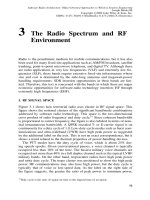
Node-Le vel Ar chitecture
Analysis
This chapter analyzes node-level software radio architecture. Attention turns
to the internal functions, components, and design rules within a radio node.
The canonical node architecture partitions software-radio functions into seg-
ments within which functions are functionally cohesive, and between which
the segments are data-coupled. T his approach conforms to well-established
principles of
structured design
[183, 184]. SD has been superseded in contem-
porary practice by object-oriented technology (OOT) [185]. SDR precursor
systems to which the author contributed were organized according to the SD
principles of functional cohesion and data coupling. Message passing was a
necessity for distributed processing among multiple minicomputers and micro-
processors. These high-end military command-and-control systems employed
federated parallel processing. Full-custom ASICs and s pecial-purpose digi-
tal signal processing boards were integrated with a dozen minicomputers and
over 100 Intel-8080-class microprocessors to create early cutting-edge signal
processing capacity. This progenitor technology anticipated the emergence of
commercial DSP chips and boards by about ten years. The design principles of
functional cohesion, data coupling, and message passing developed then apply
to software-radio architecture today. The military progenitor systems, however,
prioritized mission effectiveness, maximizing technology insertion with cost
as a relatively unconstrained variable. In the application of SDR technology
to both military and commercial domains today, cost is a highly constrained
input-variable. Therefore, the node-level architecture analysis treats cost and
other externally imposed design constraints (e.g., standards) as explicit design
rules.
OOT has matured the foundation principles of SD, adding features that pro-
mote software reuse. For example, UML, as an OOT computer-aided software
engineering (CASE)-tool, integrates complementary views of a collection of
objects. Use-case scenarios, logical structure, components, and deployment
aspects may be developed independently, but UML assures that they are con-
sistent for the set of objects being defined. This chapter develops the SDR
node-level application of OOT and UML. This is not merely another treatment
of object-oriented design. Instead, architecture emerges as an object-oriented
framework for the peaceful coexistence of o therwise mutually incompatible
(structured, object-oriented, and ad-hoc) designs. As DSP technology has
171
172
NODE-LEVEL ARCHITECTURE ANALYSIS
Figure 5-1
Aspects of architecture.
developed, available processing capacity has increased according to Moore’s
Law. Radio functions have been packaged into analog RF, digital hardware,
and software many times. A slow ly evolving set of functions has been re-
peatedly rehosted into a rapidly evolving set of (hardware-intensive) compo-
nents. Node-level design principles have evolved through this process into the
software-radio architecture strategy defined in this chapter .
I. ARCHITECTURE REPRESENTATION
As illustrated in Figure 5-1, an architecture is a framework in which a specified
family of functions may be accomplished via specified classes of components
according to specified design rules. In this figure, architecture is represented as
a collection of associated concepts with little obvious structure. The node-level
analysis of software radio architecture begins with the organization of hard-
ware components so as to maximize software flexibility. The hardware com-
ponents include wideband antennas and RF/IF processing, wideband ADCs,
DACs, parameter-controlled ASICs, FPGAs, DSPs and general-purpose pro-
cessors. The software components consist of data structures and procedures
organized into software objects. The analysis process begins with an exami-
nation of consistency and conflicts among functions, components, and design
rules.
Consider the static hierarchies illustrated in Figure 5-2. These functions,
components, and design rules characterize a top-level radio function. In this
case, the function is to “transduce voice from [auditory] compression waves to
radio waves.” This function may be implemented via a processing thread that
ARCHITECTURE REPRESENTATION
173
Figure 5-2
Radio architecture map.
begins with the microphone. The ADC component converts the signal from
the microphone into a sampled baseband signal. A DSP algorithm vocodes
the voice waveform efficiently, and another imparts the channel coding. A
baseband DAC converts the signal to analog so that analog IF/RF stages can
up-convert and impart it to a carrier.
In this representation o f architecture, the mapping between the “voice trans-
ducer” function and the hardware and software components are more explicit
than in Figure 5-1. In addition, the relationship between components and de-
sign rules has been made explicit. During the design stages of a project, the
emphasis is on allocating functions to components. The components also are
subject to the constraints of design rules. During the integration stages, the
emphasis shifts to the verification that components implement functions while
adhering to the design rules.
Business considerations create another dimension of design rules. A need
to control costs may be met through the reuse of a (notional) “Sanyo enclo-
sure.” That module brings packaging constraints. These may violate thermal
design rules. Many subsystems will be overspecified or overconstrained. One
must therefore sacrifice some performance constraint or violate some design
rules slightly to achieve a realizable, affordable design. During development,
the components must be verified to accomplish the allocated functions. They
must be tested to assure compliance t o type-certification design-rules, such as
radiated power and EMI limits.
Continuing with Figure 5-2, the middle series of boxes (e.g., “Acquire
Voice,” “Microphone,” etc.) shows how one might hierarchically decompose
the top-level functions. The resulting sequence of subordinate functions may
be associated with other subordinate components. These are associated with
other design rules. Reading across the figure, the subordinate function “acquire
voice” is allocated to a microphone component. This notional component has a
174
NODE-LEVEL ARCHITECTURE ANALYSIS
Figure 5-3
View of a traditional function hierarchy.
built-in analog compander. The notional VCELP codec complies with the de-
sign rule “avoid banjoman.” Th ere is a condition in GSM when the RPE-LTE
algorithm resonates due to bit errors in a way that sounds to Americans like
someone is playing the banjo, making a twanging sound. VCELP avoids this
sound under severe BER conditions. The associated design rules encompass
power, packaging, design, and performance issues. This yields an interlocking
web of constraints that can easily become tangled unless subjected to rigor-
ous engineering discipline. One simple but reliable engineering discipline sug-
gested in the figure is the identification of one-to-one relationships between
functions, components, and design rules. One-to-one (1 : 1) relationships lo-
calize the issues associated with tradeoffs. With 1 : 1 relationships, the steps
needed to meet specific technical, performance, or schedule goals are clearly
allocated a specific subsystem or component. This greatly simplifies the trade
space, reducing the time and effort required to reach design decisions.
A. Functional Design Hierarchies
The structure of a representative functional design hierarchy is illustrated in
Figure 5-3. This is a three-dimensional view, with input on the left, output on
the right, and higher levels of abstraction organized vertically. The top-level
function “transduce voice” is hierarchically partitioned into the subordinate
ARCHITECTURE REPRESENTATION
175
functions “acquire voice,” “code voice efficiently,” and “impart to carrier.”
These three functions accomplish the isochronous signal flow as shown in the
bold arrows. The user interface and the packaging of control data is accom-
plished in the companion flow of control messages.
The structured design (SD) concepts of cohesion and coupling provide con-
crete criteria for partitioning the software into modules. Cohesion is the rela-
tionship among elements within a module. Functional cohesion is the tightest
and hence most desirable kind, representative of the relationship b etween a
function and its arguments. Yourdon defined other types of cohesion ranging
from functional as the tightest to incidental as the loosest. In incidental co-
hesion, functions in a module share little or no relationship with each other.
Modules may be coupled to each other through passing data (e.g., message
passing), the loosest form of coupling. They may call each other, which is
a tighter form of coupling. If they exercise internal control over each other’s
internal functions, or cause unanticipated side effects, they are maximally cou-
pled. Data-coupled modules may be changed independently with no side ef-
fects. Data coupled, functionally cohesive modules are the ideal.
Techniques for getting to well-structured designs include the creation of
functional flow diagrams and descriptions
(F2D2). In Figure 5-3, the lowest
level is represented in F2D2. A sequence of rigorous descriptions of the func-
tions and interface are included in a formal F2D2 product. One also must
examine the interfaces among the resulting modules (e.g., the coupling of the
modules) by creating an
N
2
diagram. This is a matrix with modules listed
on the rows and columns. The values in the matrix represent the interfaces
among the modules. The analysis process should yield interfaces that are well
defined, complete, and consistent.
To go beyond design into architecture, one must consider a collection of dif-
ferent designs. The collection of designs should include designs produced by
different teams a t the same time, and designs that evolve over time. Consider
the reuse of the software components that resulted from the functional decom-
position above. A serious difficulty in the reuse of such software components
becomes evident trying to map a functional component, the voice processing
thread, into the hardware and software configuration hierarchies (Figure 5-4).
The configuration hierarchies express packaging for configuration manage-
ment. The figure shows a configuration hierarchy within which the notional
handset’s voice transducer could be configuration-managed. The Mobile Sta-
tion (MS) hierarchy includes hardware and software components. As illus-
trated, the voice processing functional thread is distributed across codec, pro-
grammable RF IC, and TMS320 DSP chip. Which software functions are al-
located to which components? This is not clear because the functional compo-
nents are distributed in dedicated hardware and in software algorithms. A high-
quality architecture framework therefore should help one express the func-
tional components in an intuitively appealing, but implementation-independent
way. That framework must also map these slowly evolving functional compo-
nents to the rapidly evolving hardware and software components.
176
NODE-LEVEL ARCHITECTURE ANALYSIS
Figure 5-4
Configuration hierarchies obscure functional relationships, increasing the
cost of component reuse.
Figure 5-5
Design rule hierarchies further complicate design t radeoffs.
Design rule hierarchies complicate matters further as suggested in Figure
5-5. Design rules may be driven by customer-centric marketplace values in-
cluding quality and aesthetics. Competition-centric values such as adherence
to standards for compatibility and reuse of components for low cost may take
on a central role in some design tradeoffs.
ARCHITECTURE REPRESENTATION
177
Figure 5-6
Design rules from complementary disciplines feed a design-rule reposi-
tory.
When design rules are in harmony, the design tradeoffs are straightforward.
Keeping subjective quality high, adherence to standards, and low cost harmo-
nize in the narrow choice of a voice-coding algorithm. They are often not in
harmony, however. There may be a conflict between reusing components and
driving the form factor to a reduced thickness. Algorithm tradeoffs often in-
fluence size, weight, and power in a handset. The robust algorithms generally
require more processing capacity and hence more powerful, power-hungry
chips. It is thus helpful to find a design framework within w hich the entire set
of issues related to functions, hardware and software components, and design
rules are most manageable.
The open-architecture framework should impose the minimum design rules
necessary to insure that architecture objectives are met. The objectives of open-
architecture are often mutually contradictory. For example, open-architecture
needs to both promote commonality and encourage competition. Commonal-
ity means buying components of one design, while competition requires one
to buy components from multiple suppliers. The solution to this technical
quandary invariably rests on a social process of letting competing interests
pull in opposite directions until everyone is equally unhappy, but still willing
to participate in the architecture. Architecture analysis facilitates that process
by making the tradeoffs clear . It can also facilitate the process by providing
mechanisms that allow one to hide or safely ignore contentious issues. For ex-
ample, the banjoman phenomenon applies only to a particular GSM vocoder.
The avoid-banjoman rule may be hidden as a vocoder-specific constraint in a
multistandard open-architecture framework. Once the banjoman phenomenon
becomes known, however, that knowledge should be retained for future use
in appropriate circumstances.
An enterprise-architecture repository of design-rules can serve this pur-
pose. The design-rules repository of Figure 5-6 illustrates such a knowledge
178
NODE-LEVEL ARCHITECTURE ANALYSIS
repository. An enterprise may maintain its own repository of s uch rules, com-
prising part of its own intellectual property and competitive advantage. With
the growth of open taxonomies on the World Wide Web, an open design-rule
repository for software radio could emerge as a network of web- accessible
domain-specific design rules. Industry bodies seeking to promote open soft-
ware-radio architecture could adopt the minimum set of design rules neces-
sary to insure the benefits of the open-architecture framework. It could defer
the majority of the design rules to (centralized or distributed) design- rule
repositories. Those developers with a vested interest in sustaining the knowl-
edge required to successfully integrate hardware and software components
into functioning systems that obey
all relevant
design rules would cooperate
to maintain shared design rule repositories, e.g., in a users’ group.
B. Object-Oriented Approaches
Object-oriented design incorporates the core strengths of SD, while increasing
the cohesion among data and algorithms. Objects encapsulate functionally
cohesive components. SD criteria assist one to decide which software functions
should be coalesced into an object. There are incidentally cohesive objects,
as well as functionally cohesive objects. The incidentally cohesive objects
built in C++ can be as hostile to reuse as spaghetti-coded FORTRAN. One
mayuseOOTasawaytomoveforward,buildingonestablisheddesign
principles including SD and message-passing. One may then build on the
principles of functional cohesion and data coupling in defining SDR object
boundaries.
OOT makes significant progress beyond the basics, however, as illustrated
in Figure 5-7. Objects encapsulate data and associated procedures, called meth-
ods, into a single software entity. Object classes are reusable by definition.
Objects are instantiated from classes and new classes are d efined i n terms
of existing ones. The figure illustrates the reuse case in which three existing
object classes are merged to quickly create a vocoder. The assumption is that
the developer has experience with voice coding, having developed a general
vocoder class and other voice processing algorithms. The general voice-codec
class, first of all, would define primitive digitized-signal flows. This could in-
clude double buffering and clock-synchronous delivery of speech data to the
modem stream. SDR applications of OOT emphasize the isochronous opera-
tion of such multi-object processing threads.
A more specific class, the RPE-LTP algorithm of GSM, may be based
on this general-purpose voice codec class. A notional Regular Pulse Exciter
(RPE) vocal tract modeling algorithm is then combined with a Long-Term
Predictor (LTP) analysis/synthesis and filtering algorithm. The new algorithm
inherits the properties of each of these existing algorithms. This includes slots
for data embedded in the objects. It also includes attached methods that define
object behaviors. Newly created classes may override behavior from ancestor
classes by declaring their own local methods.
ARCHITECTURE REPRESENTATION
179
Figure 5-7
Object hierarchies promote software reuse.
Objects are coupled by message passing, institutionalizing as it were the
good practice of data-coupling software modules. Message passing is a gen-
eralized form of remote procedure call since most messages need a response.
The response may be regarded as a value returned from a procedure call. Mes-
sage passing that requires the sending object to wait is, in fact, equivalent to
a procedure call. Threaded message passing, however, does not require the
sending object to wait for the response. Java’s threading facility [186], for
example, implements this aspect of OOT.
Messages may invoke public methods and may access public data struc-
tures, which the object makes available to the outside world. Objects may
also use private data structures and methods, promoting reuse in another di-
mension. In the example, the “convolve” operation has been defined earlier.
Convolution is a common operation that may be useful in both RPE-LTP and
a channel demodulator. Convolve( )
23
is not a public method of RPE-LTP, but
it is an internal operation from which the class is composed. The demodulator
also employs Convolve( ). Thus the Convolve( ) operator may be drawn from
a general-purpose library and used in both objects as a private method ac-
cessible only by members of the RPE-LTP (or demodulator) class itself. This
approach effectively reuses the existing Convolve( ) code.
23
Methods and function calls are indicated by the notation MethodName( ), by OOT convention.
180
NODE-LEVEL ARCHITECTURE ANALYSIS
Figure 5-8
Radio platform model integrates hardware and software characteristics.
There are several perspectives from which one may define objects like the
vocoder or Modem. Some constraints on the vocoder may be evident from
a use-case vignette that characterizes Q oS. Working through such scenarios
allows one to define objects in terms of their interactions with external enti-
ties. T his is called
use-case analysis
. Other constraints m ay become evident in
packaging the vocoder for deployment in an ASIC.
This brief introduction highlights aspects of OOT that are relevant to soft-
ware-radio architecture. OOT provides the analysis and system design frame-
work for software design de veloped in later chapters. The core notions of
OOT include the encapsulation of objects by defining public slots and meth-
ods. Property inheritance allows specific objects to inherit slots and methods
from more general classes of objects. OOT facilitates message passing as a
generalized procedure call. It then couples object instances into a cooperative
distributed processing framework, including support for multiple independent
execution threads. Polymorphism a lso helps software developers gracefully
extend existing functions to new data structures and behaviors. Related OOT
literature includes introductory texts [31] and in-depth treatments of object-
oriented design for real-time systems [187].
C. Reference Platform Integration
OOT is readily extended from software design to hardware, software, and
systems integration. Figure 5-8 illustrates an object-oriented way to define the
relationship between hardware and software. The software provides the per-
ARCHITECTURE REPRESENTATION
181
sonality of the object, while the radio-platform provides the analog and digital
processor hardware. Together, the software objects executing on the platform
define a rich set of behaviors that are properties of the composite radio node.
Some algorithms use more power than others. Power consumption is there-
fore a property of software and hardware. Standby power may be a hardware
characteristic, but algorithm intensity will either use power conservatively or
aggressively, changing the dynamic power consumption properties of the radio
node.
Software is not the only thing that gives hardware personality. Physical
switch settings may change the b ehavior of a chip, device, b oard, o r other
configurable hardware. The addition of daughter modules of different types
may also change the properties of a platform. There are two ways to specify the
radio platform. Traditionally, acquisition organizations wrote a specification
that defined exactly what was required. Such specifications often constrain
design, reducing competition and restraining the introduction of new technol-
ogy. The more contemporary approach, introduced earlier is to specify only
the essential features of the hardware necessary to support a wide family of
software personalities. T his statement of features is the r eference platform.
The end item may be modeled as an object that consists of two constituent
objects: the hardware platform and the software personality. If the hardware
fully complies with the reference platform, then the software personality will
integrate successfully. By minimizing the feature set of the reference platform,
compliant hardware has maximum degrees of freedom.
In Figure 5-8, a software-radio personality is suggested as a software state
machine that includes Setup, Idle, Active, Receiving, etc. The host hardware
is suggested as a mix of analog RF, ASIC, FPGA, DSP, programmable
INFOSEC modules with a general-purpose host processor, plus some inter-
networking hardware interfaces. In planning the migration of existing services
from current hardware to new hardware, one must define a reference-platform
that captures the essential features needed t o assure the integrated b ehavior. In
particular, the desired features of the personality must be quantified in terms of
demands that must be satisfied by the host radio platform. The set of quantified
capacities of a radio platform is also call ed its “ca pability.” Given a quantified
capability, the required capacities may be summarized in the reference plat-
form, and provided in the rehosting process. This assures the necessary level
of integrated performance in the new hardware environment.
Figure 5-9 illustrates how the demands of personalities must be met in the
capabilities of platforms in order for the desired performance to be achieved.
The notional software radio system of the figure includes RF, modem,
INFOSEC, and internetworking components orchestrated through some con-
trol component(s). The RF object needs suitable carrier frequencies, band-
widths, and dynamic range from the host analog RF components. Although
there are many parameters that one may use to characterize the analog com-
ponents, few parameters are as critical to SDR performance as bandwidth and
linear dynamic range. These are carried through the architecture from antenna
182
NODE-LEVEL ARCHITECTURE ANALYSIS
Figure 5-9
Capability quantification is essential to rehosting.
to wireline (e.g., DSO) or user interface (e.g., audio, video). Other param-
eters such as processing capacities are relevant to the configurable and pro-
grammable components including ASICs, FPGAs, DSPs, and general-purpose
computers. These capacities are measured in
m
illions of
i
nstructions
p
er
s
econd
(MIPS),
m
illions of
o
perations
p
er
s
econd (MOPS), and or
m
illions of
fl
oating-
p
oint
o
perations
p
er
s
econd (MFLOPS). They may also be measured with re-
spect to an industry-standard instruction mix such as the SpecINT or SpecFP
[46]. End-to-end performance characteristics such as quality (e.g., BER), quan-
tity (e.g., number of channels, data rate), and timeliness (e.g., queuing delay)
are the behaviors of the composite radio that are defined through balancing
the demands of the personality against the capacities of the host c omponents.
ITU-T recommendation H.320 [188] for video-teleconferencing and Micro-
soft’s TA PI [189] plug-and-play specifications both incorporate the capability-
based approach for plug-and-play. Since the implementation of radio platform
capabilities strongly influences software, the analysis of capability-based de-
sign is deferred to the software chapter.
D. Using UML to Analyze N ode Architectures
UML has evolved from early OOT approaches. Its current evolution includes
increased emphasis on real-time and embedded applications [190]. UML mod-
els a system as a collection of objects with an associated set of relationships.
At the systems level, these relationships are characterized intuitively in terms
of views. The four UML views of a system are:
use-case view
,
logical view
,
component view
,and
deployment view
. Use cases are scenarios that express
ARCHITECTURE REPRESENTATION
183
Figure 5-10
UML model of voice radios.
the behavior of a system in terms of its relationship with external actors. The
logical view defines objects, classes, states, relationships, and interfaces along
the lines developed above. The component view addresses the partitioning of
the functionality of the logical view into (hardware and) software components
with associated interfaces. Finally, the deployment view defines how compo-
nents are related to physical entities. The analysis of radio node architecture
is readily framed in terms of these four views.
1. UML Objects
A variety of graphical notations has arisen for describing
the views and the objects of which a system is comprised. An object that
implements the “voice transducer” function introduced above may be called a
Voice Radio object. It is characterized in UML notation in the model of Figure
5-10.
The legend shows that the solid box represents a class, a generic object
that embodies the concept of a voice radio. The dotted boxes, in this case, are
instances. So My Radio “is a” voice radio, and Your Radio “is a” voice radio.
The lines connecting the boxes represent relationships among objects. In this
case, the IS-A relationship is useful. The arrow points from the more specific
class to the more general class of object.
Each class and instance has an
identity
, shown at the top of the object-box.
Each object has a set of
attributes
that ar e like
slots
into which values or other
objects can be placed. The attributes of the instances have specific values,
184
NODE-LEVEL ARCHITECTURE ANALYSIS
which define the
state
of that object. The procedures attached to software ob-
jects define
behaviors
. Some object-oriented software a pproaches ca ll these
methods
. The physical properties of hardware devices may define their behav-
iors. In addition, UML allows one to assign
relationships
to objects. An object,
then, is defined in terms of its set of attributes, behaviors, states, identities,
and relationships.
2. Regarding Object Notation
Sometimes it is appropriate to be fanatical
about notation. In this text, it is essential to be completely relaxed about no-
tation. The motivation for this perhaps unusual treatment is that the software-
radio architect has to be able to distinguish concept from notation. Defining
architecture is about finding common ground among players who may never
have spoken to each other before and who almost certainly do not use the same
notation. Thus, the architect has to see beyond the notation to the underlying
design frameworks. Within OOT, there are a variety of object notations, includ-
ing Jacobson’s [191], Booch’s original approach [192], Coad-Yourdon [193],
and real-time object-oriented systems analysis (RTOOSA) [194], to name a
few. They have been integrated in UML, but one may find (documents or)
practitioners that use the earlier approaches.
The use of multiple apparently ad-hoc notations in this text is not sloppy.
The treatment is designed to give the reader practice needed to develop the
skills to see through the notation. In addition, the notation used in this text is a
simplified version of UML, tailored to convey the core concepts useful to the
analysis of software-radio architecture, without making this a text on UML.
3. Radio Classes, Subclasses, and Instances
The example of Figure 5-10
shows the attributes of the class Voice Radio, as well as the specific values
of those attributes at some point in time on My Radio and Your Radio. At
some point, it will become clear that My Radio is just an AM/FM broad-
cast receiver, w hile Your R adio i s a push-to-talk (PTT) transceiver. If that
difference is important, two subclasses of Voice Radio could be created. The
creation of subclasses makes it easier to recognize members of the class. For
example, My Radio has no microphone, so its Transmit() function is null. One
can represent My Radio as an instance of Voice Radio that has a null Trans-
mit() function. If it is clearer or more helpful to the architecture-definition
objective, a Broadcast Receiver class may be defined, as illustrated in Figure
5-11.
4. Components in UML
The structure of the components of the radio may
also be expressed in UML, as in Figure 5-12. From one’s knowledge of radio,
it should be clear that the arrows represent the way in which one object is a
component of another. The intervening classes are not populated, but the leaf
nodes are those classes that are specific enough to make into instances (e.g.,
actual hardware and software components). The function “transduce voice”
from above can readily be represented in this notation.
ARCHITECTURE REPRESENTATION
185
Figure 5-11
The subclass establishes specific capabilities and de fault values of slots
and behaviors.
Figure 5-12
UML-like representation of a voice radio.
E. A Topological Model of Architecture
24
The need to efficiently map radio functions to hardware configurations leads
to the study of the mathematical foundations of system architecture. There
are few. When two radio systems engineers with different backgrounds ap-
proach a systems-level design problem, they often come up with different
approaches and solutions. The focus of this text is on architecture and hence
on the common aspects of those endeavors, on systems engineering. How
24
This section covers an advanced topic that m ay be safely deferred to a second reading.
186
NODE-LEVEL ARCHITECTURE ANALYSIS
does one go about deciding which approach is the best? Anyone who claims
some “optimal” approach or general way of determining “best” in any univer-
sal sense is probably making a n over-statement. Mathematical optimality may
be formulated over mathematically tractable spaces. But systems engineering
is defined over rugged, nonlinear spaces comprised of sets of overlapping
functions to be deployed on somewhat inappropriate components according
to mutually contradictory design rules. The complexity of the full trade-space
thus defined is too large and complex to be represented as input for contem-
porary optimization tools. The term “optimal” may be accurately applied to
carefully identified sub-problems such as carrier tracking in Gaussian noise.
At present, it cannot be accurately applied to radio node architecture in the
broad sense used in this text.
1. In Pursuit of Commonality
Systems design problems of any import deal
with large, complex systems either in isolation or in combination. A national
telecommunications system, for example, is a complex system; shipboard elec-
tronics for a battle group and the avionics suite of a new fighter jet also ex-
emplify complex systems. In addition, today’s large-scale telecommunications
systems architectures are concerned with “systems of systems.” That is, each
component of a large-scale system is itself a very complex system. The na-
tional infrastructure (telecommunications, power, fuel, water, etc., all more
or less interconnected) provides a good example of a system of [complex]
systems. Researchers now categorize such systems as complex adaptive sys-
tems [195]. Some mathematical principles illuminate the quest for architecture.
These principles take some study, the highlights of which are provided here
and in [196].
What does an airborne avionics system consisting of communications, radar,
navigation, IFF and a fly-by-wire control system have in common with a
ground-based mobile military communications system? They both use RF, but
avionics may prioritize remote sensing and navigation while the ground-based
system m ay prioritize overcoming impairments of RF propagation in a battle-
field environment. Both systems have signal generation, modulators, antennas,
receivers, signal processors, embedded control and information systems, and
user interfaces. Common use of the RF spectrum reveals much commonality.
The radar and communications systems encompass radiated power, bandwidth,
free space loss, and reflections. Some reflections result from a target, while
others result from multipath reflectors. Both need noise suppression, and the
correction of distortions introduced through propagation. Both use correlation
gain to enhance t he received signal, to correct errors, and to present r esults to
a user. There are many shared abstractions and similar components. In addi-
tion, packing electronics into rugged enclosures applies disciplines of power
distribution, thermal management, and control of electromagnetic interference
(EMI). Thus, there are shared abstractions and technologies that differ widely
in implementation. But the search for unifying
mathematical
principles that
reflect the commonality is elusive.
ARCHITECTURE REPRESENTATION
187
Figure 5-13
Radio functions may map onto system components.
2. Toward Mathematical Structure
Consider, however, Figure 5-13, which
shows radio functions associated with system components. The figure gives
an impression of a one-to-one relationship between functions and components.
The figure, of course, is an abstraction that oversimplifies the situation. Nev-
ertheless, figures like this give the (sometimes erroneous) impression of good
design. Does this “nice” quality perceived w hen functions and components
have a one-to-one (1 : 1) relationship have further support? That is, does this
quality derive from mathematical foundations or can it be defended based on
mathematical principles?
The topological model of software radios [196] shows that there is such a
mathematical basis. Let
P
be a set of primitive functions (“primitives”) such
as “RF Band Selection,” “Channel Selection,” etc. as illustrated in Figure
5-13. Each primitive function
P
ij
operates over some domain,
D
i
,whichis
a
set
of inputs over which that primitive is defined. This primitive yields a
set
of results, the range,
R
j
, of that primitive. Some sets have rich structure.
For example, filters, Fourier transforms, and wavelets are defined over vector
spaces, which are metric spaces in which the additive group is commutative
(Abelian), and the multiplicative group is Abelian [432]. Vector spaces obey
distributive laws and the triangle inequality. This is a
lot
of mathematical
structure. Most software functions have no such rich mathematical structure.
A simple if-then-else statement, for example, might check the state of the
receiver (e.g., the “carrier present” flag), wait a prescribed amount of time,
and invoke a carrier fault-recovery process. Recei ver state is a set of labels
asserted by other algorithms.
Carrier fault recovery
isthenameofthesoftware
process to be invoked. Such processes have mathematical structure [197], but
there is no vector space in which a control state maps to a software process.
Such a software process has a
point set topology
,however.Thisisaset(e.g.,
of state labels, process names, etc.) with a family of subsets (e.g., the ones
over which the software operations are valid) that has topological properties.
3. Topological Spaces
A topological space is a set,
X
, and a family of subsets,
O
x
, which includes
X
and the empty set. The family is closed under union
188
NODE-LEVEL ARCHITECTURE ANALYSIS
and finite intersection [198, 199]. Point set topology is the study of families
of subsets, functions over them, and mappings among them. Consider a set
of states that a transmitter may assume such as “Transmit,” “Receive,” “Ini-
tialize,” and “Ready.” Let the set of such states be the set
X
. The control
algorithm
C
(
x
), may be defined such that exactly one state
x
contained in
X
(cf.
x
"
X
) may be asserted at any t ime. The domain of
C
is:
Dom(
C
)=
#
Transmit, Receive, Initialize, Ready
$
=
X
%
X
%
=4
But what is the topological structure of this domain? If exactly one
x
"
X
can be asserted at any one time, then
C
is defined over
##
Transmit
$#
Recei ve
$
#
Initialize
$#
Ready
$$
=
O
X
. T hat is, the state of the transmitter may not be
#
Transmit, Receive
$
, which would correspond to the situation that the radio is
transmitting and receiving both at once. This might be acceptable for some
radios, but not for one controlled by
C
. Each subset of
X
that is allowed is in
the control space. Topologically, the individual states are singleton subsets.
C
is not defined over the empty set unless the state set contains the null set (
Á
),
the empty set. The rule
C
(
Á
)=
C
(Initialize), for example, defines the default
state. The extended topology is:
##
Transmit
$#
Receive
$#
Initialize
$#
Ready
$
Á
$
=
O
X
A topological space, however, must include
X
.Since
C
(
S
) is undefined,
O
X
is not a topological space. If one can induce a topological space on a software
radio function,
all
of point set and algebraic topology becomes mathematical
foundations for that function. If not, then the topologies could be embedded in
a larger topological space that yields insights into the mathematical structure
of software radio. For example, the product topology is the set of all subsets
of
X
,
O
P
:
O
X
&
O
P
How could one define
C
(
X
)?
X
,
C
’s domain, is a property of the algorithm
C
.Thatis,
X
is implicit in
C
. Historically, documentation may express that
C
is defined over
X
. To explicate that implicit relationship, d efine
C
(
X
,
x
),
x
"
X
.
C
(
X
,
x
) is the generalization of
C
that “knows” that it is defined over
X
. The informal knowledge is formalized in
C
(
X
,
x
). This leads one to define
the
Topologically Explicit Functions
: Functions defined over a domain
X
with
an explicit topology (
X
,
O
X
) and range
Y
with explicit topology (
Y
,
O
Y
)are
topologically explicit if
X
,
Y
,
O
X
and
O
Y
are computationally accessible. They
are topologically well-structured if the topologies are topological spaces.
In the example,
X
=
#
Transmit, Receive, Initialize, Ready
$
and
O
X
=
#
X
,
#
Transmit
$#
Recei ve
$#
Initialize
$#
Recei ve
$
Á
$
ARCHITECTURE REPRESENTATION
189
Is
O
X
a topological space? To test this, consider u nions and intersections of
the members of
O
X
.Transmit
'
Ready is in the set of unions over the members
of
O
X
, but it is not in
O
X
. Therefore, this topology is not a topological space.
It could be extended to define some value of
C
for this condition. Since the
behavior of
C
specifies that such a condition is an error, the topology may be
extended to capture this notion mathematically. In particular, define
©
as the
distinguished symbol that represents an error condition. This is similar to the
use of
Á
to represent the empty set.
O
X
may be extended w ith
©
:
O
X
=
#
X
,
#
Transmit
$
,
#
Receiv e
$
,
#
Initialize
$
,
#
Receive
$
,
Á
,
©
$
One writes
#
Transmit
'
Ready
$
and all the other erroneous combinations,
as members of the distinguished subset
©
, which is shorthand for all those
combinations. A convention says that anything that is not explicitly listed in
O
X
as a valid member of the domain is one of the items that
C
(
X
,
x
) will
recognize as not valid, and to which it will raise an exception. This is an
extension of
C
. It has some mechanism (e.g., a lookup table) for testing its
input
x
against
O
X
(not just against
X
). If
x
is not in
O
X
, then it asserts
©
.
This shorthand
©
is not merely an editorial convenience. There are a huge
number of possible topological spaces for any finite set X. The power set of
X
is the set of all subsets of
X
.Since
X
has four elements, there are 2
%
X
%
or 2
4
=
16 members of the power set ranging from
Á
to
X
including the four single-
tons
#
Transmit
$
, etc., the six doubletons
#
Transmit,R eceive
$
,
:::
#
Initialize,
Recei ve
$
, the four triplets
#
Transmit, Receive,Initialize
$
:::
#
Receive,Initialize,
Ready
$
,
Á
,and
X
itself. A topological space may include just
Á
and
X
,which
is called t he
indiscrete topology
. Or it may include th e power set, which is
called the
discrete topology
. Or it may be any of the 2
(2
%
X
%
(
2)
possible ways of
taking subsets of the power set. For
%
X
%
=4, there are 2
(16
(
2)
=2
14
or over
16,000 ways to construct topologies—subsets of
X
—because the number of
topologies is a double exponential. Instead of forcing one to pick through this
intractable number of combinations, the
©
con vention embeds
O
X
in
O
P
.By
defining the range of each primitive as a topological space, one may express
all software radio primitives as maps over topological spaces.
4. A Topological Framework for Architecture
If a function is defined ab-
stractly using UML, then its input and output spaces are defined, and the asso-
ciated topological spaces may be inferred. In addition, since UML allows one
to model hardware or to produce executable code, the topological properties
may be extended to maps from abstract functions to hardware and software
implementations. Such maps over topological spaces have useful mathematical
properties including composability by the glueing lemma [199]. For example,
if there is a map from an abstract function to a software module and thence
to host hardware, the properties that have been demonstrated to be true of
the abstract function are proved true of the hardware version. This can reduce
type certification from an exhaustive testing process to a matter of checking
190
NODE-LEVEL ARCHITECTURE ANALYSIS
Figure 5-14
Software radio as a topological space [200].
that the topological maps defined in the (future) CASE tool are implemented
in the hardware. This checking process is linear in the complexity of the
hardware, whereas the testing of combinations of downloads, etc. is quadratic
in the number of software modules.
In addition, one may compare the range of one primitive to the domain
of another using a topological map called a
homeomorphism
, a topology-
preserving mapping. Homeomorphisms are ONTO and 1 : 1 and they preserve
topological properties (e.g., the inverse set-theoretic images of open sets
O
X
are open in
O
Y
under homeomorphism). So the desired relationship between
a host processor and the function may be grounded in the theory of point set
topology. One constructs the homeomorphism between the functional repre-
sentation and the hardware representation. If the function is implemented in
software, the homeomorphism is constructed between the functional abstrac-
tion in UML and the object implementation in C, Java, or F ORTRAN and
assembler.
This topological approach allows us to more precisely define other systems
engineering issues such as the quality of the implementation and the resources
required to host a software radio on a given hardware suite as illustrated in
Figure 5-14. Defining the topological properties of the domain and range of
each software radio primitive is an exercise in mathematical rigor . It helps de-
termine the slots of the software objects. It can also help define the conditions
over which complex functions such as control procedures are defined. Con-
structing the topological space may assist in identifying defaults and related
behaviors of the objects.
The construction of topological sp aces can be done by someone who knows
topology theory using a knowledge-engineering approach. This is the way that
the author has applied these principles except in rare cases where the design-
ers had strong mathematical backgrounds. Alternatively, future CASE tools
ARCHITECTURE REPRESENTATION
191
can be designed to guide the non-mathematician software-engineer through
the potential topologies by a question-and-answer dialog. A data dictionary
defines the dimensions of the topological spaces present in a software-radio
system. The CASE tools could be extended to interpret the spaces over which
the d ata elements are defined. Current CASE tools can check for consistency
and completeness, but they cannot check even simple topological properties.
RF, for example, is defined on a quantized subset of the real line. Valid RF
values have to be properly quantized. That is, if RF is defined in the FM
band, it should be quantized in 100 kHz steps, while in the AM broadcast
band, it is quantized in 10 kHz steps. The FM band is the set
X
,andthe
values of
f
c
)
FM-Band are in
O
X
. Similarly, the CASE tool could process
the U ML to extract the discrete topology present in control variables, and
could ask the user about combinations of conditions that the control algo-
rithm does not explicitly check. It could thus induce
X
and
O
X
for each algo-
rithm
C
.
In general, software radio objects defined on topological spaces may be
defined with explicit spaces so that the functions may be more readily reusable.
If
C
(
X
,
x
) is defined explicitly , then
C
can be accessed from a software reuse
library based on
X
.If
X
is RF, then the systems engineer has the ability
to browse a reuse library based on RF. This may facilitate finding modules
that may be modified to accomplish a new function. So there may be practical
benefits to this somewhat abstract and unfamiliar treatment. This concludes the
brief introduction to the topological model of software radios. The interested
reader may pursue the topic further via [201 and 99, e.g., in 433].
F. The Canonical Software Radio Node Architecture
Structured design principles admonish one to maximize cohesion within a
component. Functional cohesion is evident in components whose elements
share some common element. Applying this principle to SDR node architec-
ture yields a grouping of functions that share common RF, IF, and baseband
elements. Figure 5-15 shows the resulting segments of the software-radio node
architecture. The power man agement and LN A elements of the RF conversion
segment share the antenna, while the RF conversion elements share the RF
frequency standard. The RF elements also share a need for proximity to the an-
tenna. The LNA is placed near the antenna in order to set the system sensitivity.
The power amplifier is near the antenna in order to deliver power efficiently
to the antenna. The RF section may be placed remotely from IF processing
(e.g., in diversity architectures). IF processing is therefore distinguished as a
separate segment. The IF elements of a superheterodyne transceiver also share
frequency standards. In PTT and FH radios, the transmitter and receiver IF are
tightly coupled. In addition, IF processing in an SDR filters the wideband sig-
nal structure from the RF segment to yield the narrower b aseband bandwidth.
The transformation of bandwidth across the IF section therefore enhances its
functional cohesion.
192
NODE-LEVEL ARCHITECTURE ANALYSIS
Figure 5 -15
Canonical model of SDR node architecture.
ADCs may be inserted at the interface of IF to RF or IF to baseband, provid-
ing a basis for data-coupling between these segments. The baseband segment
performs the modem functions, converting information between channel code
and source code. This cohesive function is the basis for defining baseband as
a segment. Soft-decision decoding delays the final transformation of channel
symbols to baseband bits. It is therefore more cohesive with the baseband
segment than with the bitstream segment.
The bitstream segment performs operations on bitstreams. This includes
multiplexing, demultiplexing, interleaving, framing, bit-stuffing, protocol stack
operations, and FEC. Turbocodes combine interleaving and FEC, exemplify-
ing the functional cohesion of the bitstream segment. Control is included in
the bitstream segment because of the digital nature of control messages. This
may place the user-control interface in the bitstream segment. The source
segment includes the user speech signal, the local source and sink of audio
information. Source coding is the transformation of communications signals
into bitstreams. This may occur locally (e.g., in a soundboard) or remotely, at
the other end of the PSTN. This segment is coupled to the bitstream segment
by standard bitstream interfaces such as DS0, T1/ E1, or a LAN. Although this
formulation of the source segment permits a geographically distributed seg-
ment, the segment is functionally cohesive. Each of these segments is therefore
functionally cohesive. Each accomplishes a single clearly identified function
or closely related set of functions. In addition, the RF, IF, and baseband func-
tions transform the data rate or bandwidth between input and output, typically
by an order of magnitude or more.
These segments therefore comprise the canonical software-radio node ar-
chitecture. This canonical form brings out aspects of architecture that are not
highlighted in the functional architecture of Chapter 1. One could also for-
mulate these segments as objects. Each segment is one object. The states of
the segment are the slots of the object. The transformations of the segments
ARCHITECTURE REPRESENTATION
193
are the behaviors of the objects. W hen simulated or implemented in software,
each behavior corresponds to a method. When implemented in hardware, a
behavior simulates a property of the hardware.
The primary signal flows of the canonical architecture are illustrated in
Figure 5-15. There are two primary signal flows. The transmitter chain, first,
transforms of source from its original analog waveform to a bitstream. The
bitstream is further encoded and multiplexed. Channel coding is applied to the
signal, which is then upconverted, amplified, and filtered for transmission at
the antenna. The receiver chain, second, transforms the air interface waveform
received at the antenna. Frequency selection, filtering, frequency translation,
equalization, demodulation, error control, demultiplexing, and source coding
yield the information signal to the user or to the PSTN interface.
The segments of this model may be mapped to the functional architecture
and interfaces introduced in Chapter 1. The canonical model, however, explic-
itly represents properties of RF hardware (e.g., Local Oscillators) that are not
explicit in the functional model. One of the goals of architecture is to facilitate
the mapping of functions to hardware. Although there are many issues to be
addressed in establishing such a mapping, the following three stand out:
1. Determining the node-level properties of antenna(s), RF conversion, and
IF processing
2. Placing the ADCs and DACs at an appropriate interface point
3. Accommodating INFOSEC design criteria
Subsections consider these aspects of mapping to hardware in turn. The
analysis of each of these areas refines the canonical model.
1. Refining the RF Reference Platform
The characteristics of the antenna(s),
RF conversion, and IF processing determine the radio node’s access to the RF
environment. A radio design would specify the parameters of each of these
segments. Architecture, on the other hand, specifies the absolute minimum
necessary to assure that a specific radio function will be supported by the
RF platform. It is convenient to encapsulate a consistent set of radio functions
that implement an air interface with the associated physical data link, network,
and applications interface functions as a waveform. To visualize the analysis,
consider the generic block diagram of Figure 5-16.
Although the mix of antennas is intentionally unusual, the block diagram
highlights RF platform issues. The physical placement of the antennas, for
example, will determine the degree of coupling among them. If the antennas
are sectorized, then each RF path has azimuth and elevation coverage. In a
deployment, the antenna would be pointed in a specific direction. The value
of this direction is not relevant to architecture, but controllability of direction
is significant. Gimbaled antennas and phased arrays require tasking and/or
control from some processor. These functions require control flow across seg-
ment interfaces, and any such f lows are architecturally significant. Antenna
194
NODE-LEVEL ARCHITECTURE ANALYSIS
Figure 5- 16
RF-related radio platform.
gains must be known for propagation modeling. Any other programmable
parameters are also architecturally significant.
The RF conversion segment is matched to the antenna segment. Each an-
tenna requires at least amplification and filtering, and this function is assigned
to RF conversion on a 1 : 1 basis for each antenna element. RF conver-
sion therefore sets the bandwidth of RF access for each antenna path. Since
transmission on one band may interfere with reception on that band or on
other bands, RF conversion may include active cancellation circuits. Alterna-
ti vely, an RF cancellation path may be processed at IF or baseband, increasing
the number of RF-IF chains. Internal calibration and/or built-in-test-elements
(BITE) also increase the number of RF paths.
N
RFpaths
=
N
anten nas
+
N
cancellation
+
N
BITE
If RF conversion includes a superheterodyne stage, then RF conversion
yields analog IF at some reference frequency. The distribution of reference
frequencies is a critical design issue for SDR. Raising the choice of IF into
architecture imposes design constraints on the internal structure of the re-
cei ver. This choice may be encapsulated in a receiver component to protect
intellectual property. Alternatively, it may be unencapsulated to allow antenna-
RF modules to be acquired separately from the IF/baseband components. An
architecture that forces all players to make the same design decision lacks
flexibility but promotes competition for interchangeable antenna-RF mod-
ules. An architecture that allows both encourages the inclusion of a variety of
transceiver designs, promoting competition at a different level of aggregation
of components. The purpose of this text is not to propose specific solutions
to such conflicts. Instead, it is to define architecture alternatives, pointing out
the strengths and weaknesses of the alternatives so that the reader may make
ARCHITECTURE REPRESENTATION
195
informed decisions. As one probes deeper into the mapping of functions to
components, such conflicts are constantly arising.
There may be fewer IF processing paths than RF paths. A diversity com-
biner, for example, accepts multiple RF-segment inputs, producing a single
IF output. IF filtering also d efines the ch annel bandwidth,
Wc
, available to
the baseband segment. There may be multiple programmable bandwidths. IF
conversion defines the reference frequency,
f
0
, of the interface to the base-
band segment. In addition to these primary segment-level parameters, other
parameters may have architectural implications for the RF reference platform
at some point in the future.
Finally, there are RF platform-level parameters. The RF and IF conversion
stages often share common frequency control and timing references. Since
many waveforms require a minimum level of frequency stability, this is an
architecture-level parameter. In addition, many waveforms require knowledge
of time to a specific accuracy and precision. If one thinks of the RF platform as
encapsulating the analog aspects of the radio platform introduced in Chapter 1,
then the RF platform parameterizes the timing capability of the radio platform.
The RF reference platform thus consists of that minimum set of features
of antennas, RF conversion, and IF processing necessary to support a set of
communications applications. The RF platform is further described in Table
5-1.
2. Placement of the ADCs and DACs
Several approaches are feasible for
the conversion of analog RF signals to digital form. The first is to not con-
vert signals from analog to digital at all, but to extract the information con-
tent directly. A direct-digital-RF receiver extracts b aseband b itstreams from
the (filtered) RF waveform without RF conversion. A direct-conversion re-
ceiver, similarly, may include one stage of RF conversion to IF equals zero
at which the information-bearing bitstream may be extracted. A CDMA rake
receiver, similarly, may consist of three matched-filter despreaders that yield
information-bearing bitstreams, tracking Doppler and delay, and managing
bitstream timing internally. These alternatives encapsulate the entire RF-IF-
baseband process in one module within which bitstream extraction happens.
A high-quality architecture allows for these possibilities.
Alternatively, wideband ADCs and DACs may be placed at the RF-IF inter-
face or at the IF-baseband interface. For cell site applications, the placement of
wideband conversion at the RF-IF interface of a superheterodyne conversion
receiver enables digital IF processing. This choice is less likely for handsets.
3. INFOSEC-based Partitioning
INFOSEC imposes an additional partition-
ing on radios that seek to provide transmission security and/or encryption.
Bitstreams may be either encrypted or unencrypted. INFOSEC practice desig-
nates the encrypted bits with the color black. Unencrypted bits are designated
red bits. The bitstream segment, then, is partitioned into an encrypted black
subsegment, an INFOSEC module, and an unencrypted red subsegment. The