Kiến trúc phần mềm Radio P11 potx
Bạn đang xem bản rút gọn của tài liệu. Xem và tải ngay bản đầy đủ của tài liệu tại đây (2.21 MB, 37 trang )
Softwar e Radio Arc hitecture: Object-Oriented Approac hes to Wireless Systems Engineering
Joseph Mitola III
Copyright
c
!2000 John Wiley & Sons, Inc.
ISBNs: 0-471-38492-5 (Hardback); 0-471-21664-X (Electronic)
11
Software Ar chitectur e
Tradeoffs
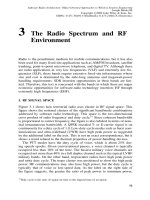
This chapter addresses software design for SDR nodes. This includes soft-
ware functions, hardware-software interactions, object-oriented design, and
software architecture. I t also addresses the evolution of the software compo-
nents of SDR designs. A rchitecture tradeoffs addressed include the partitioning
of software into objects. The boundaries of functional-interfaces and levels of
abstraction determine the potential for reuse. These boundaries also determine
the ease with which software products from different development teams will
integrate into a multi-mode SDR. Over time, the use of specialized hardware
facilities may be first encouraged and later discouraged. In addition, there are
continuing tradeoffs between system performance and algorithm complexity.
The more computationally demanding algorithms often offer better QoS than
the less computationally demanding algorithms. This puts pressure on algo-
rithm designers, software architects, and configuration managers. The analysis
presented in this chapter provides insights into how these tradeoffs shape SDR
architecture.
The technical focus remains on the internal structure of SDR nodes. Net-
work-level software architectures are as important as internal structure, but
are beyond the scope of this text. Texts on specific air interface standards
address networking issues [351–353], as do general wireless communications
texts [354]. This text focuses on the process of structuring the software of
high-performance SDRs, and on the architecture implications of the resulting
software components.
I. THE SOFTWARE DESIGN PROCESS
The tradeoffs of this chapter are set in the context of Figure 11-1. A specific
SDR implements a subset of the radio functions shown. A top-down software
requirements-statement should include services, numbers of channels, radio
bands, and modes. In addition, a hardware platform may be specified, or its
characteristics may be defined in a reference platform.
It is possible to design SDR software top-down from requirements and radio
functions to be targeted to a class of radio platforms (e.g., base stations, mobile
nodes, etc.). It is not wise to embark on a purely top-down design process,
however. SDR technology includes many existing components, with more
347
348
SOFTWARE ARCHITECTURE TRADEOFFS
Figure 11-1
Top-lev e l radio node architecture.
added daily. The current commercial emphasis on wireless mobile computing
and Internet access is producing software components for reuse. Corporate
experience invariably includes one or more baseline systems with components
that management envisions as potentially reusable whether they were designed
for such reuse or not. Therefore, software follows a hybrid of top-down and
bottom-up design. The top-down aspect identifies the behaviors and top-level
partitioning of SDR software into objects. The bottom-up aspect identifies
existing software components that may be encapsulated into objects at some
appropriate level o f abstraction to avoid the work of designing, coding, and
testing those components again.
The functional model of Figure 11-1 is the basis for the partitioning of
software into components. This model was derived b y examining hardware-
software partitions of SDR technology-pathfinders and precursor systems.
Software functional entities and associated top-level interfaces have exhib-
ited strong consistency over time and across implementations by different
teams. The functional model is therefore the top-down framework. The pro-
cess iterates between top-down and bottom-up aspects to yield software objects
organized into a class hierarchy.
II. TOP-DOWN, OBJECT-ORIENTED DESIGN
Top-down SDR software design is presented in this section.
A. Object-Oriented Design for SDR
This section further explains OOT principles introduced earlier. The
aspects of OO design that support top-down software development in-
TOP-DOWN, OBJECT-ORIENTED DESIGN
349
Figure 11-2
Partial object model of a simple modem.
clude encapsulation, message passing, property inheritance, and polymor-
phism.
1. Encapsulation
The first step in the development of object-oriented mod-
els, whether for modeling, simulation, or software development, is the identi-
fication of the object c lasses. This is accomplished by drawing a conceptual
circle around a cohesive set of data and functions to define an object. Initially,
one treats the entire radio node as an object in order to define its behaviors
when stimulated by the external world. This encapsulates the entire system
including software as one object. Subsequently, one defines the constituent
software objects of which the radio node is comprised. A consistent set of
software objects constitutes one of the radio’s personalities. These lower-level
objects provide the well-known radio functions of filtering, modulation, de-
modulation, timing and control, as well as objects that handle protocol stacks
and user interfaces. The software objects should encapsulate groups of func-
tions in ways that make sense to radio engineers, to promote object reuse and
technology insertion.
The Modem class illustrated in Figure 11-2 provides a convenient example.
Encapsulated object classes within the modem interact with each other to
accomplish modem tasks by exchanging messages.
2. Message Passing
When a radio application sends a message to the Modem
object to “modulate a baseband bitstream,” it is effectively executing a proce-
dure call of the Modem object’s Modulate( ) method. To do this, the calling ob-
ject executes Modem.Modulate( ), sometimes noted as Modem
"
Modulate( ).
Early OO languages like LISP Machine LISP employed explicit message pass-
350
SOFTWARE ARCHITECTURE TRADEOFFS
ing using syntax like Send(Modem, Modulate(bits)). This sent the Modem ob-
ject a request to modulate bits. Contemporary OO languages like Java employ
the more concise message Modem.Modulate(bits).
Message passing permits conceptually simple integration of software com-
ponents. It also facilitates interconnections across physical boundaries of
ASICs, FPGAs, DSPs, and GP processors. Layering includes the process of
translating messages from one format to another. Tunneling includes the pro-
cess of setting up a software path to a hardware entity. The driver software
encapsulates the hardware by making public methods available to other objects
in the system.
In addition, interrupt service routines and interprocess communication typ-
ically is based on message passing using the distributed processing approach.
This has nothing to do with object-oriented d esign. On the other hand, the
historical use of message passing in distributed processing makes it easy to
encapsulate a processor as a software object. One may thus jointly address the
needs of distributed multithreaded multiprocessing and object-oriented soft-
ware by message passing. The path of transformations of a message defines
a thread, in this framework.
The clear, “public” definition of the messages—syntax and semantics—is
necessary for the successful integration of software and hardware. Types of
messages useful in object interfaces include:
#
Setup and control,
#
State and state transitions,
#
Information s treams (an infinite sequence of messages of a specific for-
mat), with specified timing constraints,
#
Timing and frequency-standard information,
#
INFOSEC information such as the current level of protection on each
channel,
#
Operational parameters like hardware and software signal gain (which
impacts linearity), and
#
Resource needs and capabilities (e.g., for plug-and-play).
A data dictionary that includes the format (syntax) and meaning (semantics)
of the messages should provide examples of when to and when not to use a
given message. A comprehensive data dictionary also includes names for at
least the public slots and methods of all objects in the system. The degree of
“publicity” required is determined by the scope of the software components.
If only new, locally designed software objects are to be used, then teamwide
agreement on slots and messages suffices. If objects from multiple teams are
to be used, then the agreement has to embrace all the teams. In particular, if
the purpose of an SDR architecture is to engage all of industry in the creation
of third-party products, then the data dictionary of messages should be part
of the open architecture standard.
TOP-DOWN, OBJECT-ORIENTED DESIGN
351
3. Property Inheritance
When a new object class is synthesized from exist-
ing object classes, that new class inherits data slots and behaviors. One may
create an inheritance hierarchy with a generic Modem class at the top and with
subclasses such as FSK-Modem and PSK-Modem. Alternatively, one may de-
fine Modem in terms of constituent objects, Modulator and Demodulator, with
states that determine whether the object operates in PSK or FSK mode. In the
example of Figure 11-2, the latter approach is taken. The m odulation type and
baud rate of the constituent objects are inherited from the Modem class in
which they are defined.
Property inheritance allows one to define reusable classes of generic soft-
ware objects like FIR filters, timing recovery, packet multiplex objects, etc.
From these, one may synthesize task-specific objects like mark and space
filters. The Filter inheritance hierarchy might begin with Filter at the root.
Properties of the Filter might include pole-zero structure (e.g., FIR, IIR, etc.),
for example. FIR Filter components could include time-delay storage elements
and feed-forward weights.
The simple modem of Figure 11-2 recovers the carrier, extracts bit tim-
ing, estimates signal parameters (e.g., to estimate whether a mark or space is
present), and makes bit decisions. It demodulates FSK using mark and space
filters. The bit-decision object compares the energy in the mark and space filter
at the appropriate time, deciding for mark or space based on the strongest filter
energy. Since the mark and space filters are F IR filters, they i nherit properties
from the FI R filter class. The o bject model shows the constituent c omponents
of the modem. That is, the modem is constructed from software components
like the mark and space filters that inherit their properties from other object
classes. The Modem object dispatches Modulate( ) and Demodulate( ) tasks to
the Modulator or Demodulator objects. It might perform only error checking
and time synchronization internally, delegating essentially all the behaviors to
its constituent objects. These objects inherit Modulation Type and Baud Rate
from the aggregator class, the Modem.
4. Polymorphism and Operator Overloading
Polymorphism is the a bility of
a software object to assume different behaviors as the context dictates. The
classic case is operator overloading in which the same operator, say “+”, be-
haves differently for different data types. The + operator can do conventional
addition on two scalars. Instead of being undefined for two vectors of unequal
length, for example, an overloaded + could do an element-by-element addi-
tion starting at the first element of both vectors. To do this, the definition of +
is augmented with a method that is invoked when both operands are vectors.
Similarly, the addition of a scalar to a vector could be accomplished with the
same + operator with a different method that adds the scalar, say, to every
element of the vector. The + operator dynamically examines the types of its
operands to invoke the appropriate method.
Operator overloading makes it much easier t o write readable code. It also
makes the code assume a degree of
independence of the underlying data struc-
352
SOFTWARE ARCHITECTURE TRADEOFFS
tures.
That is, operator overloading allows a given algorithm to operate on a
range of different data structures.
The Modem object could overload Modulate( ) if the input bitstream were
packetized. A packetized stream includes a header containing control infor-
mation and a body containing the signal [e.g., 331]. Modulate( ) could check
the packet header and apply the type of modulation defined in that packet.
Similarly, Demodulate( ) could be overloaded. In this case, it would need a
modulation-class recognition algorithm in order to know whether to apply
FSK, PSK, etc. to the signal. In traditional radio architectures, the channel
modulation is rigidly defined by the air interface. In 3G, howe ver, the channel
modulation may range across several types as a function of QoS and SNR. The
channel could use BPSK in low-SNR and 16 QAM in high-SNR conditions.
In lieu of mode-change commands that waste channel capacity, the Demodu-
late( ) function could be overloaded, applying the appropriate demodulation
algorithm for whatever signal is present.
A Filter-class’s behavior could be overloaded as well to be either block
oriented or stream oriented. When a filter with
N
taps is presented with a data
block of length
M
, it could load
N
internal delay states from the prior block,
filter the
M
samples, and save the
N
internal states for use in the next block.
When the same f ilter is p resented with a s tream, it could pop the first el ement
from the stream, apply the filter weights to the current
N
values in its delay
line, and return one filtered sample. Loading and saving filter values must be
efficient f or such software to operate in real-time. Objects facilitate efficiency
through access to data structures in the slots. The Filter object, for example,
can allocate a new delay line with different taps to each stream. The object
then applies its (presumably highly optimized) multiply-accumulate algorithm
to the appropriate slot(s) yielding the results without physically loading or
storing the data.
Thus, the principles of encapsulation, message-passing, property-inheri-
tance, and polymorphism are useful in SDR contexts.
B. Defining Software Objects
One may apply the principles of object-oriented design to the design of an
SDR node in a top-down way, as outlined in this section.
1. Context Diagrams
The context diagram treats an entire system as if it
were a single object. Given the system as an encapsulated object, one must
answer the question: What “messages”—in the most generic sense—will be
exchanged with the outside world?
Figure 11-3 illustrates this process for a notional mobile telephone switch-
ing office (MTSO), including the base stations, transmitters, etc. This particu-
lar MTSO includes BTS and BSC functions to simplify the discussion. Thus
defined, the MTSO includes radio and nonradio telecommunications functions
necessary to make a mobile SDR node work with the larger PSTN.
TOP-DOWN, OBJECT-ORIENTED DESIGN
353
Figure 11-3
Illustrative context diagram.
The air interface, network management interface, and operational network
interface provide access to external objects like subscribers and networks.
Abstract external objects like callers and networks are called
actors
in UML
terminology. Actors have properties and/or behaviors that shape the system
design. Between the MTSO and each external system there are two arcs, one
for each direction of stimulus and response, which are modeled as message-
passing. The air interface represents the MTSO’s connection to the mobile
subscribers. In this case messages include traffic channels and control chan-
nels. In c ontemporary digital air interfaces such as GSM and IS-95 ( CDMA),
virtual channels are multiplexed over physical channels. There also may be
channels for establishing timing (e.g., CDMA pilot channels) in a complex
array of streams. From these, isochronous traffic channels (message streams)
and formatted control packets (messages) must be recovered.
The context diagram identifies all signal flows, data flows, and control
flows with external entities. Signal flows are isochronous streams. Data flows
contain near-real-time data packets. Control flows shift processor use among
software objects. These flows may be defined in part by air-interface stan-
dards. Specific designs invariably introduce nuances, such as the application-
specific use of air-interface bits that the air-interface standards leave unspec-
ified.
2. Event Lists
The context diagram is examined for external events that may
stimulate the system. Applicable messages from the air interface, status re-
quests from the telecommunications management network (TMN), and calls
placed through Signaling System 7 (SS7) from the PSTN are examples of
external events. Each must elicit an appropriate response from the software.
For each external event, there may be more than one system response. These
are collected into a comprehensive event-response list.
354
SOFTWARE ARCHITECTURE TRADEOFFS
Figure 11-4
Layered c ontext with event lists.
From the usual object-oriented design perspective, one builds the software
objects that recognize the external events and generate the required responses.
For SDR applications, this enumeration of external events and system re-
sponses must be tempered by considering the interface layers. These are mech-
anisms through which the outside world imposes on the radio constraints of
external events and responses that give rise to events unanticipated in the initial
analysis. The layered context illustrated in Figure 11-4 includes the radio prop-
agation environment, which adds noise and interference. Interference may cre-
ate false messages and may mask le gitimate messages from subscribers. This
interaction is taken into account by expanding the external-events list. One
may establish positive acknowledgment across the air interface with timeouts
and back-off mechanisms to ensure that a masked message cannot cause a
permanent suspended state of a critical resource like a traffic channel.
Reception and transmission events might include pointing a smart antenna
to maintain high CIR on a specific subscriber. In addition, the reception/
transmission layer will constrain some interfaces to observe the demanding
timing requirements of the Synchronous Digital Hierarchy (SDH) or SS7.
On the other hand, the Interfaces layer may provide some hardware relief to
the software challenges. SDH products, for example, include T and E carrier
chip and board-level interfaces. These meet many of the SDH requirements
provided the SDR fills buffers fast enough (but not so fast as to overflow).
Having examined these context layers for events that may not have been
present in the initial context diagram, one defines an initial set of software
objects.
3. Use-Case Scenarios
The event lists contain stimulus response pairs among
actors. It is instructive to trace the p ath of such pairs through the system.
TOP-DOWN, OBJECT-ORIENTED DESIGN
355
Figure 11-5
Object interaction threads.
Figure 11-6
Sequence of objects with related actions.
Such a trace may be called a thread. The top-level trace of a caller dialing a
respondent, for example, is shown in Figure 11-5. If Caller and Respondent
are not on the objects list as actors, they are added. In addition, the dialing
event is placed on the events list if it is not already there. T racing threads
provides a good check on the events lists while providing a natural basis for
encapsulating objects and defining message flows. As illustrated in Figure
11-6, the trace reveals the existence of Caller, handset, MTSO, PSTN and
Respondent objects with associated message flows. In UML terminology, the
tracing of t he interactions among external actors and the encapsulated system
is called
use-case analysis
.
The effects of these top-level objects on the internal structure of the MTSO
are shown in Figure 11-7. The thread extends from stimulus to response in-
side the MTSO. The dialed number is presented in an appropriate signaling
structure of the air interface. In first-generation cellular systems, all dialing is
expressed in a time-shared c ontrol channel accessed via a physically distinct
analog receiver. In the SDR, this channel is one of many accessed in the wide-
band RF, IF, and ADC streams. In a first-generation scenario, this channel is
accessed at the air interface by wideband analog antenna. It is translated in
frequency and filtered to a wideband IF where it is converted from analog to
digital via the ADC. In Figure 11-7, these operations are performed by the
RF/ADC segment, yielding a w ideband digital stream. The RF/ADC segment
encapsulates the antenna, RF, and IF processing segments of the canonical
model and the ADC of the hardware reference platform. Those details are hid-
den in this encapsulation because the focus is on the top-level objects. Since
objects employ message passing for interobject communications, one may
model the wideband digital stream as an infinite sequence of single-sample
356
SOFTWARE ARCHITECTURE TRADEOFFS
Figure 11-7
Sequence of internal objects and message flows.
messages. Digital filtering and down-conversion is then accomplished by an
IF processing object called the Channel Filter. It produces a control-channel
stream. In a first-generation system, this would be a 25 or 30 kHz bandwidth
analog stream sampled discretely at perhaps 50 k samples per second. In a 2G
air interface, there are multiple types of virtual control channels, multiplexed
onto physical data bursts. Object-oriented modeling of 2G protocols segregates
the physical representation from the logical representation. The Channel Filter
object has transformed the wideband digital stream “message” structure to a
narrowband stream.
The next data transformation in the figure is to extract the dialing infor-
mation from this narrowband channel. Figure 11-7 shows the Dialing Extrac-
tor object performing this transformation of the narrowband control-channel
stream into a Dialed Number packet. The narrowband control-channel s tream
from the IF Processing object has not yet been demodulated from the sampled
(Manchester coded) waveform into information bits, so the dialing extractor
accomplishes at least two things. First, it demodulates the control channel
into a 20 kbps data stream. Next, it processes the protocol of the bitstream to
extract the dialing information. This behavior is acceptable in a process of ob-
ject refinement. Abstractions allow one to consolidate functions that appear in
more than one radio object into abstract objects. Ultimately the D emodulator
object, which supports this Dialing Extractor object, would be aggregated into
the control-channel Modem object. Dialing information is a packet of format-
TOP-DOWN, OBJECT-ORIENTED DESIGN
357
Figure 11-8
Illustrative MTSO inheritance hierarchy.
ted d ata, so the Extractor object has transformed both the format and data rate
of the data stream. These dialing data packets must meet SS7 timelines.
Next consider the internal data stores. The formal object design methods
have different nomenclature and formats for many different kinds of classes,
objects, and relationships. These may be useful in rigorous object-oriented
modeling. In this text, a variety of notations provides practice in interpret-
ing alternative notations for the OO concepts. In Figure 11-7, data stores are
differentiated from transforms. Signal transformations are evident in the dif-
ferent notation for signal streams versus packet streams. Thus, the notation is
tailored to express the concept being studied. Contemporary OO technology
often does not allow alternative representations that reflect different analytical
objectives. At this stage of top-down analysis, alternative representations can
be helpful.
Finally, the dialed number is validated. Ancillary data (e.g., the MTSO’s
identifying data, SS7 message type, etc.), is looked up in the data store. The
Dialing Director appends it to the dialed number for presentation to the PSTN.
The PSTN Dispatch object handles the details of the interface to SS7. Behav-
iors of the objects thus are defined by the needs of the thread.
4. SDR software object representation
This process continues with the anal-
ysis of additional threads until all stimulus-response pairs have been analyzed
to determine data transformations and object behaviors. One result of this
process is the definition of an MTSO object class diagram, as illustrated in
Figure 11-8. In this example, the system consists of front-end signal process-
ing classes and back-end packet processing classes. The tentative objects cre-
ated earlier have been allocated appropriate roles. All of the front-end objects
process streams of sampled signals at specific sampling rates and arithmetic
precision. The signal-processing class contains the code that efficiently moves
358
SOFTWARE ARCHITECTURE TRADEOFFS
streams around, but does nothing else, leaving that to the subordinate objects.
The back-end objects expect packets of bits as input data structures, trans-
forming the packets and passing them on through the isochronous stream to
the PSTN. The relationships (dashed arrows) show the signal flow paths. The
Decoded Channel Bits Interface arises naturally as the interface between sig-
nal processing and bitstream processing. The Dialing Extractor object is no
longer explicit since its functions have been subsumed into other objects. It
can be maintained as a
ghost object
that checks the behavior of the modem,
packetizer, and number formatter. Such objects may be implemented as ab-
stract classes that check the behavior of the objects that are supposed to be
doing the work. Such objects are useful in ensuring that downloaded objects
have not violated constraints. Alternatively, the Dialing Extractor may be used
as a waveform-independent object that implements dialing behavior by calling
the waveform-dependent modem, protocol stack, etc.
The information flows among the objects are threads. Only one isochronous
thread is illustrated in Figure 11-8. Threads are classified as isochronous, near
real time (NRT), or noncritical. Isochronous threads must be accomplished
within short timing windows. In OO software environments that support mul-
tiple inheritance (e.g., C++), the isochronous thread may be a class that checks
the timing constraints. These constraints may be slots in the objects that are
on such threads. The thread-object could then aggregate the timing budgets of
each constituent object, keeping track of the probability that constraints can
be met and detecting conflicts. In other OO environments (e.g., Java), the tim-
ing constraints may be expressed as relationships among objects (e.g., Java
“Interfaces”). Timing constraints of NRT threads are not severe, but timing
budgets and constraint checking can be helpful. NRT constraint violations can
be expressed to users so they expect slower performance, (e.g., of the user in-
terface). Other NRT constraint violations can be used to create back-pressure
flow control into the network to reduce the demands on the node.
C. Architecture Implications
Each SDR design team creates the threads, objects, slots, and methods that are
tailored to th e needs of the project. Thus, two SDR object structures are rarely
identical. SDR architecture may embrace this diversity in two ways. First,
industry-standard open architecture should specify only the minimum, highest-
level aggregated classes necessary to define plug-and-play interfaces among
the objects. The simple front-end/back-end partition at the top level of Figure
11-8, suitably augmented, would be a minimalistic approach. The subordinate
object classes of that figure may not be entirely appropriate. The front-end
objects of channel filter and modem map well to radio subsystems, so they
might be the basis for a more fine-grained architecture. But the behaviors of
dialing director and PSTN dispatch may not be as appropriate since they are
subsets of more complex protocol stack functions not shown in the hierarchy.
The reusability of software objects, then, is determined by the structure of
SOFTWARE ARCHITECTURE ANALYSIS
359
Figure 11-9
Software radio architecture objects “bubble chart.”
functions in the object class hierarchy. Characterizing the issues that shape
SDR class hierarchies is therefore the focus of this chapter.
Second, enterprise architectures should promote migration paths among
object representations. Different teams may like to express the same concept
in different ways, but that alone may not add value. The maintenance of an
enterprisewide SDR architecture provides the standard classes that should be
shared, facilitating constructive object reuse. License to abuse the enterprise
architecture is as important as having one, so that creative alternatives are not
inappropriately suppressed.
III. SOFTWARE ARCHITECTURE ANALYSIS
Given the above introduction to top-down object-oriented techniques, one may
analyze existing software to determine its architecture implications.
A. SDR Software Architecture
Iterative top-down design and bottom-up implementation processes refine ob-
jects. The resulting objects are then structured into aggregates. This process
yields the generic software architecture illustrated in Figure 11-9. The top
row of high-level objects control the system while the lower rows implement
the radio channels and related services. The mix of antenna, waveform, and
channel processing front-end hardware and software shown is representative
of a contemporary mobile or base station node. (The INFOSEC hardware
module and back-end processor/bus hardware is not shown in the figure for
simplicity.)
360
SOFTWARE ARCHITECTURE TRADEOFFS
TABLE 11-1 Characteristics of Radio So ftware Objects
Radio Objects Object Methods a nd Slots
Antenna and RF Control (ARC) TX/RX, Power, Polarization
Channel Control (CC) Allocate Resources, Configure, State Machines
Waveform Processor (WP) Generation, Timing, Fault Detection, Mod/Demod
INFOSEC Control (IC) Key, Control Bridge to Black Side, Authenticate
INFOSEC P rocessing (IP) Encrypt, Decrypt, TRANSEC
System Control (SC) Initialize/Shutdown, Test, System Status
User Interface ( UI) Commands and Displays
Speech Processing ( SP) Echo Canc ellation, Voice Coding
Protocol P rocessing (PP) Packetization, Routing, VGC Modems
Each of t hese high-level object classes has a fine-structure which ultimate-
ly consists of primitive single-function radio objects like filters, modulators,
interleaving, clock recovery, bit-decision objects, etc. The protocol and
speech processing objects implement protocol stacks such as ATM, TCP/IP,
Mobile IP, etc. Consequently, internetworking to the wireline infrastructure
consists of a few relatively monolithic/predefined (e.g., COTS) software ob-
jects.
Continuing with Figure 11-9, it is clear that the top-level objects of the
software radio strongly reflect the characteristics of the hardware. Nodes
organized around such objects exhibit the behaviors summarized in Table
11-1.
B. SPEAKeasy I Software Architecture
The SPEAKeasy I system was developed in Ada according to DoD criteria
for software quality. Accordingly, the lowest-level Ada packages are generally
small—less than 100 lines of code (with a couple of notable exceptions such
as built-in-test). The SPEAKeasy I software system as built consists of the
modules described in Table 11-2.
Like any other software suite built on a schedule, the as-build code has some
strong features—such as the handling of timing and the real-time p erformance
—and some weak ones. Since an Ada implementation was mandated, there is
no real-time executive except the Ada run-time kernel and library. In addition,
the state machines were apparently hand-coded. Such code is less reusable
than a Z.100 SDL equivalent. The degree of reverse engineering required to
understand the code varies from package to package as a function of the style
of the programmer. As a result, some packages had redundant comments such
as
$
A = B + C; Add B and C together to get A
$
, when it would have been more
helpful to say “The net timing offset, A, is the sum of the base system time,
B, and the network offset, C.” Nevertheless, studying as-built code reveals
design patterns.
SOFTWARE ARCHITECTURE ANALYSIS
361
TABLE 11-2 SPEAKeasy I Software Arch itecture
Module LOC
Module Descriptions
/Functions
At (127 kB)
C040 interprocessor communications
BIT (318 kB)
Built-in-test packages
, including CRC, EEPROM, PID,
I/O regiesters, interrupts & DMA
Cm (1.29 MB)
Configuration m ana gement
ALE (125 kB)
Automatic Link Establishment Rx & Tx functions
ALE
Rx1 (378 kB)
ALE receiver mo dules
Hvq (645 kB)
Have Quick communications ensemble
Hvq
Ct (109 kB )
Control modules
(Initialization, Mode Control, Errors)
Hvq
Glob (25 kB)
Globals
Hvq
Rx (379 kB )
Receive
mode (Synchronize, TOD, Rx, Active
:::
)
Hvq
Tx (131 kB)
Transmit
mode
Work (299 kB) ALE packages & specs
Hfm ( 518 kB)
HF modem communications ensemble
Hfm
ctrl (58 kB)
Controls
waveform start/stop messages; protocol
events; PM query; TX/RX Done (local);
Hfm
dc (22 kB)
Data control
packages, source messages, error
checking
Hfm rx (289 kB)
Receiver
bit & me ssage operations, text I/O, Rx
utilities, data correlation tables, filters, q ueues
Hfm tx (149 kB) Squelch,
TX
/RX mode,
TX
templates, RF Control,
Timing
Nbg (334 kB)
Narr owband frequency hopping
Nbg
ct (49 kB) State Machine, Sync Loss, TX/ RX, Waveform, PTT
State
:::
Nbg glob (105 kB)
Globals
for NBG package
Nbg
hp (57 kB)
Hop Packages
—timing, data request/processing, PTT
ack, crypto processing
:::
Nbg rx (73 k B)
Receiver pac kages
MFSK, Preamble, Galois (FEC),
Dead Bits, Flags, Bitsync, RX flush, Det/Track
Nbg
t (49 kB)
TX
: Amplitude, Preamble fill, IQ Sa mples, AM on
Voice, Filter, Inter-Process Communications (IPC)
Messages, SSB, DSB, QAM, OQPSK, Event &
Constraint Checking
c
! Mitola’s STATISfaction, used by permission.
C. Characteristics of Top-Level Objects
For example, typical military SDR objects include agents, databases, and chan-
nels. Databases store the load modules and parameter sets that constitute per-
sonalities. This includes filter parameters, lookup tables, and other data sets
to be loaded into a personality at run-time. If the objects are partitioned into
generic objects and a parameter database, the software need not be modi-
fied for minor changes. The code management or configuration management
system keeps track of revisions and manages multiple personalities. An SDR
362
SOFTWARE ARCHITECTURE TRADEOFFS
node that has an associated database of personalities and parameters it can be
managed, maintained, and supported in the field.
Channel objects are good abstractions around which to organize radio
modes (e.g., HAVE QUICK). A channel object may be organized as a collec-
tion of agents, software objects that perform delegated subsystems-level func-
tions of RF control, modem processing, INFOSEC, and internetworking. The
channel object obtains system resources for the waveform. These include data
flow and signal processing paths for its threads. This object installs its person-
ality on these resources to implement a mode. It then keeps track of the state
of its processing threads. Applications-level threads are needed to construct
information services from COTS applications, node services (e.g., location
finding), and radio applications (e.g., the waveform objects). The installation
of the personality consists of assigning system resources to subordinate agents
and then keeping track of the top-level state of the radio application. System
control ensures that the channel object releases system resources and removes
itself from the system when so instructed.
Agents, the functional objects that implement the personalities of the chan-
nel objects, may be organized around the top-level system functions of RF
control, modem processing, etc. Other agents may serve as hosts for buses,
manage IO processes, access timing and positioning data (e.g., from GPS),
and control the radio.
The RF control object(s), for example, determine RF direction (i.e., trans-
mit or recei ve), the RF mode (e.g., linear or nonlinear amplification); pre-
emphasis for predistortion, and frequency of transmission. For FH radios,
RF control can be fairly sophisticated, involving the use of fast-tuning syn-
thesizer hardware with transmission security features. The modem m ethods
include modulation (AM, FM, QAM, USB, MSK
:::
), demodulation, AGC
to avoid saturating or losing a signal, loop bandwidth control, and related
data packing and unpacking accomplished on protected bits. The system also
keeps track of the status of the mode, number of receivers employed, vol-
ume, data rate throughput, network parameters such as network number, and
assigned time slot(s). The system may also perform a loopback function for
network testing or local diagnosis. It has to accomplish its tasks with asso-
ciated priorities in force such as network priority, user priority, and priority
overrides.
The back-end objects include message processing, internetworking, and
managing protocol stacks. System control handles system boot-up, initial
TOD, current hop, calibration, status requests, and minimum security level.
Data structures used include base types, messages, buffers, addresses, error
condition flags, and error messages.
D. Specialized Tasks
Specialized tasks include network synchronization and waveform-unique pro-
tocols. Standard protocols (e.g., TCP/IP) are embedded in the protocol pro-
INFRASTRUCTURE SOFTWARE
363
cessing object. Timing methods manipulate the system clock. Time Of Day
(TOD) is the type of day-time format in use. Timing resolution is sometimes
measured in integer nanoseconds, but accurate only to a few hundred nanosec-
onds.
Modes may have special requirements. HAVE QUICK, for example, has
a Word of the Day (WOD) and a training list. SINCGARS employs “cue fre-
quency” messages and manages complete sets of designated frequencies called
hopsets
. Modem methods also monitor channel states including detect, fade, re-
ceiving (data, voice, carrier), transmitting, and lost carrier. INFOSEC methods
manage keys, generate cipher, select mode, status, or algorithm, and generate
TRANSEC patterns for the transmitter.
E. SPEAKeasy II Code
SPEAKeasy II code accomplished the three distinct classes of w ork illus-
trated in Figure 11-10. Communications services were supplied b y linking
waveforms. Java could construct services like radio relay across two modes
(mode bridging). A Java applet could invoke two installed radio modes to con-
struct such a bridge. Alternatively, a script could express the linking of the two
modes. In SPEAKeasy II, bridging code called the waveform agents directly.
The radio applications, the waveforms, consisted of collections of agents that
performed radio communications tasks. Each distinct mode or waveform was
a distinct radio application. In SPEAKeasy I, HF ALE, NBG, etc. were the
radio applications.
About 30 to 40% of the as-built SPEAKeasy II code does nothing but
set up paths, check to see that all the processors are powered up, move data
around, and establish what time it is in each subscriber channel. This collec-
tion of functions may be called
radio infrastructure
. Time offsets define the
difference between the system master clock and the time understood by the
channel. Without such time normalization, one could not resolve TOD differ-
ences between independently drifting S INCGARS and Have Quick networks.
Time and frequency distribution, system initialization and error recovery , data
movement, and related utility functions may a ll be aggregated into infrastruc-
ture.
IV. INFRASTRUCTURE SOFTWARE
Figure 11-11 lists the function-calls required to set up and control the phys-
ical and logical data flows inside an SDR that are the underpinnings of the
higher-level objects and services. Infrastructure code manages control flow
paths; signal flow paths; and timing, frequency, and positioning information.
In ad dition t o the software that accomplishes these functions, a resource man-
ager is needed to set up the paths and see that software objects know what
path to use.
364
SOFTWARE ARCHITECTURE TRADEOFFS
Figure 11-10
Services built on channel objects and agents in SPEAKeasy II.
Figure 11-11
Infrastructure software function calls.
INFRASTRUCTURE SOFTWARE
365
A. Control Flows
The control flow paths pass messages among objects in the system. Error log-
ging, semaphores for shared resources, and bus access protocol messages are
examples of such control data. The infrastructure functions initialize the sys-
tem, create and manipulate ports, move messages, invoke remote procedure
calls (RPC), generate multicast messages, and log error messages. Standard
protocol interactions such as Internet Protocol (IP) and User Datagram Proto-
col (UDP) used internally may also be included in infrastructure.
Port manipulation includes finding ports because in a distributed process-
ing environment, each processor creates ports at initialization which other
processors and processes use or refer to later. The FindPort method returns a
binding of the functional port (e.g., control channel 1) to the logical port (e.g.,
Com1) on a given processor. Multicast is necessary to simplify the program-
ming of multichannel operations such as initializing 100 subscriber channels
distributed among 25 DSP chips. A single multicast message will accomplish
this once the multicast has been set up to the 25 DSPs. The infrastructure soft-
ware handles the logical association of replies from the multicast recipients
for the resource manager object that issued the multicast message. The control
flow method listed in Figure 11-11 constitutes a reasonably complete set of
control flow functions necessary for this aspect of software radio infrastruc-
ture.
B. Signal Flows
The signal-flow methods listed in Figure 11-11, similarly, set up and manage
signal flow paths among processes on the same or on different processors.
These are the isochronous streams that must be complete within a short timing
window. Due to the overhead associated with path setup and teardown, these
paths must be opened and closed multiple times without being set up and torn
down again. For example, one may open Path 34 when the user of AMPS
channel 34 is speaking. One may close it when the speech epoch has ended
or when the call is terminated. The path remains set up, howe ver, so it can
be opened on every new call or speech epoch (a very efficient process), but
it need not be set up and torn down for each call (a more computationally
demanding process).
C. Standardizing Flows
Because of the heterogeneous nature of the SDR hardware platforms,
researchers and developers have identified the standardization of signal
flows as a critical step forward in SDR technology. Consider the code of
send
SimpleControlMsg (“sendSimple”) that passes a simple control message,
for example, as illustrated in Figure 11-12.
This routine declares a message object, fills in its s lots, initiates a send, and
instructs the operating system to return to the doorbell
interrupt( ) statement
366
SOFTWARE ARCHITECTURE TRADEOFFS
Figure 11-12
C-code that sends a simple control message.
when the commSend( ) function returns a value. The message type is a prop-
erty of the data exchange among the objects. The definition of message types
is supported by a header file that declares SYS
MSG SIMPLECONTROL
to have a specific numeric value for the message header. But other than this
limited degree of visibility, the interfaces among the objects are buried in
the code. In addition, commSend has to be written for every class of hard-
ware. The description and pseudocode of commSend is provided in Figure
11-13.
Good programming practice requires one to establish the ground rules for
allocating the message buffers, for making transfers efficient, and for invoking
the driver software, as is accomplished in the programmer’s notes. In addi-
tion, parameters are declared in the comments in a structured way in p art
because the operating environment did not provide higher level tools that take
care of this. It is good practice to embed such comments in the code for
the convenience of (e.g., maintenance) programmers who may not have the
development-level software tool suite, yet who must maintain the system in
the field.
The associated pseudocode is straightforward (Figure 11-14). This packet
interface code handles data setup details, errors, and transmission in a straight-
forward way. Similarly, the code itself, in this case written in C, raises no
surprises (Figure 11-15). In fact, this code is so boring that it is a colossal
waste of programming talent to have to write such code. The presence of
DEBUG in the source code is a reminder that it also has to be debugged.
This boring code has to be written and rewritten again and again for every
INFRASTRUCTURE SOFTWARE
367
Figure 11-13
Description for commSend definition comments.
Figure 11-14
Pseudocode for commSend.
new hardware platform and software environment. Furthermore, the data
exchange code, sendSimple( ), has to be written for every pair of object
classes.
Researchers at the MITRE corporation [31, 216] realized that the U.S. DoD
could save a lot of work coding interfaces among applications modules if this
whole process were simplified. In its simplest form, the idea was to define a
single object to serve as the software equivalent of a hardware backplane. Each
object could send messages to and from that object, which would translate the
format of its requests into the form other applications need. The standard
infrastructure object is the
object request broker
(ORB). Standardized ORB
interfaces reduce the number of chunks of code like sendSimple from O(
N
2
),
one for each pair of object classes, to
N
, one between each class and the
ORB. Interfaces to the Common ORB Architecture (CORB A) are declared
in the Interface Definition Language (IDL) designed for that purpose. One
industry-standard implementation of ORBs is CORBA. CORBA was intro-
368
SOFTWARE ARCHITECTURE TRADEOFFS
Figure 11-15
C code for commSend.
duced briefly early in this text. Many groups are now developing real-time
CORBA to support streaming audio and video on the Internet. CORBA makes
specific contributions to infrastructure software.
D. CORBA
The Common Object Request Broker Architecture (CORBA) has been de-
fined by the Object Management Group (OMG), an industry association of
700 co mpanies dedicated to open-architecture software. CORBA includes dis-
tributed real-time audio and video w ith the opportunity to leverage COTS
products into SDR environments. Could such audio streams provide reliable
isochronous voice channels for software radios?
1. CORBA IDL
As illustrated in Figure 11-16, CO RBA IDL allows one to
define interfaces in a group called a module. The IDL compiler processes
declarations. They may be mapped to C, C++, etc. OMG CORBA includes
extensive error checking, and a rich set of exception handlers. The IDL allows
one to declare local types for a given interface, which is equivalent to a class
in its support of inheritance. Exception handlers are structured as member
functions of the Interface class. Instead of dealing with the low-level details
of getting pointers, installing slots on message objects, sending packets with
INFRASTRUCTURE SOFTWARE
369
Figure 11-16
CORBA I DL.
byte-counts, etc., as required for sendSimple and commSend, a programmer
using IDL specifies the behavior and constraints of the interface. The IDL
compiler handles most of the related details.
The SDR Forum is using CORBA IDL in its architecture, as in Fig-
ure 11-17. In this example, the Link
Command interface has the attribute
“frequency.” In addition, two values of ModulationType are declared: AM
and FM. The Xmit interface inherits the frequency attribute and the related
exception handling from the Link
Command interface. This interface supports
the s etting of transmit c hannels and the co mmand to transmit. These interface
functions are like ORB methods. Since they are public, any other object can
invoke them to accomplish a task. Visibility is obtained into the functional
details of the interface by the use of IDL, but nonessential details (like setting
block pointers) are hidden. IDL can declare streams, packets, etc., so it is
functionally compatible with SDR needs. Computational efficiency has not
been a feature of CORBA implementations until recently.
2. Real-Time CORBA
Multiple web sites describe the performance of
CORBA implementations [355–357]. The layering of CORBA between the
operating system and the target object (Figure 11-18) challenges computa-
tional efficiency. Performance benchmarks (Figure 11-19) show that less than
1 ms is required by some ORBs to move 1 kByte arrays in Windows NT.
Since performance is steadily increasing, one cannot take these as definitive
limitations of specific products. The benchmarks are encouraging, however,
since blocks of 1 kByte of speech data (500 samples) represent a 62.5 ms
epoch. Movement of that amount of speech data in 1 ms uses only 1.6% of
370
SOFTWARE ARCHITECTURE TRADEOFFS
Figure 11-17
SDR Forum example of IDL.
Figure 11-18
ORB interface requirements.
INFRASTRUCTURE SOFTWARE
371
Figure 11-19
Encouraging performance benchmarks.
the isochronous window. While not insignificant overhead, the performance
brings real-time speech processing mediated by CORBA into the realm of
possibility.
3. Alternatives to CORBA
As illustrated in Figure 11-20, there are numer-
ous alternatives to CORBA [358]. One may employ one of CORBA’s direct
competitors like DCOM or D CE. Or, one m ay use alternative approaches like
general-purpose communications protocols.
Since the overhead of communications protocols is high, it is usually ex-
trem ely inefficient to employ a communications protocol like TCP/IP to link
objects that are running on the same computational platform. An alternative not
illustrated in Figure 11-20 is the Message Passing Interface (MPI) developed
for supercomputing applications [359]. CORBA’s computational efficiency
and acceptance in (DoD-oriented segments of) industry makes it a strong
candidate for SDR implementations. In addition, the NOSES commercial
telecommunications environment used CORBA [360] for switching software.
Technologies like Java and XML may provide future alternative m iddleware,
however. Enterprise-level SDR architecture should adopt some middleware
standard. Lighter coupling to specific middleware would ease the transition to
future alternative middleware. The US DoD has adopted CORBA as its middle-
ware standard in its Software Communications Architecture (SCA) 1.0 [437].
E. Timing, Frequency, and Positioning
In addition to efficient data movement, infrastructure software provides timing,
frequency, and positioning support. Timing, frequency, and positioning can be