Kiến trúc phần mềm Radio P15 potx
Bạn đang xem bản rút gọn của tài liệu. Xem và tải ngay bản đầy đủ của tài liệu tại đây (1.42 MB, 11 trang )
Softwar e Radio Arc hitecture: Object-Oriented Approac hes to Wireless Systems Engineering
Joseph Mitola III
Copyright
c
!2000 John Wiley & Sons, Inc.
ISBNs: 0-471-38492-5 (Hardback); 0-471-21664-X (Electronic)
15
Applications
This chapter develops illustrative applications, including the design of a con-
temporary SDR infrastructure product, the disaster-relief system.
I. THE DESIGN PROCESS
The implementation of SDR applications can be structured into an SDR de-
sign process. This process begins with the definition of a
concept of operations
(CONOPS), in which functions of the product are identified. The next stage,
system definition, includes rapid prototyping and benchmarking. The third
stage, system development, includes the implementation of hardware-software
components. Acquisition and integration of COTS components and/or system-
on-a-chip IP characterizes this stage. The expense of coding and documenting
software for reuse also may be borne in this stage. The final stage, system de-
ployment, includes platform upgrades and software downloads, with multiple
incremental enhancements.
The CONOPS provides the foundation for the development of use-cases
of object-oriented design with UML. The top-level design constraints must
be expressed as an initial set of design rules. The design rules include the
degree of openness of the architecture. If the design has an open architecture
that supports industry standards, then there may be third-party suppliers of
hardware and/or software for the product. If the design is proprietary, the
product should be unique, because it will not have the value-added features
of a robust third-party supplier program.
The functions then must be allocated to hardware and software components
that can be procured or developed within a market-driven timetable, and within
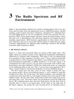
the design rules. The node design process is illustrated in Figure 15-1. Physical
design addresses the choice of components from the antenna to the user in-
terface. These components may be hardware intensive in one implementation
(e.g., in a handset) and software-intensive in another (e.g., in a base station).
The CONOPS establishes a list of RF bands and modes that the product has
to support, both initially and over its life cycle. The state of RF technology
determines how many parallel antenna-RF-IF-conversion chains of hardware
have to be included in order to support these bands. The maximum number
of
simultaneous
subscribers in each RF band and GoS define the number
of traffic channels supported per band. The number of channels plus the
482
THE DISASTER-RELIEF SYSTEM DESIGN
483
Figure 15-1
From functional design to node design.
allocated bandwidth and other parameters of the air interface define the mini-
mum bandwidth of the RF or IF ADC. O ver time, ADC technology continues
to advance, so one ADC may cover multiple RF bands. If the design de-
cisions include the use of wideband ADCs (e.g., with hundreds of MHz or
GHz sampling rates), then digital interconnect of the ADC data streams to the
processing channels becomes a high-visibility design issue.
Air interfaces and services define the software that has to be supplied. Once
the software components have been identified, the digital processing architec-
ture of ASICs, FPGAs, DSP chips, and/or general-purpose processors may
be defined. In addition, the designer must balance the need to satisfy com-
putational demands of the software against the competitive pressures of cost-
effective design. Computational demands argue for larger DSP pools while
competitive pressures tend to argue for smaller ones.
The design example illustrates the development of a CONOPS. It then
describes the methods of selecting hardware and software components, and
sizing them for a well-engineered SDR design. Subsequent analysis highlights
those features of the design necessary for it to be part of a robust software-
radio architecture.
II. THE DISASTER-RELIEF SYSTEM DESIGN
Consider the disaster-relief case study introduced previously. This section elab-
orates that case study into an SDR development project. The first step in the
484
APPLICATIONS
Figure 15-2
Concept of operations.
applications development process is to establish a vision or top-level concept
that motivates the creation of SDR applications. The vision may be a high-
level statement of a challenge (e.g., “Put a man on the moon by the end of
this decade”). Or it may be a statement of an abstract goal (“We want to own
the night”). The vision for disaster relief might imply notions like “connecting
diverse relief organizations,” “reconstituting communications,” “assisting the
stricken,” etc. To provide the foundation for a technical approach, one should
support the ideas behind the vision with a CONOPS as illustrated in Figure
15-2. The CONOPS should identify:
"
The customer for the product, system, or service
"
Thescenariosinwhichthesystemwillbeemployed
"
The benefits of the system in those scenarios
"
The people who will benefit
The following is an illustrative CONOPS.
A. FEMA Concept of Operations (CONOPS)
26
In addition to the material provided previously a CONOPS could include the
material in Exhibit 15-1.
26
Any relationship between this concept and any actual project is purely coincidental.
THE DISASTER-RELIEF SYSTEM DESIGN
485
The U.S. Federal Emergency Management Agency (FEMA) provides a
national-level pool of resources that come to bear on major disasters like
the destruction of much of Holmstead, Florida by Hurricane Andrew a few
years ago. FEMA would like to acquire a mobile system that is capable
of reconstituting local cell phone service while enhancing communications
among emergency relief personnel. The assumption is that the wireless
service has been wiped out in the disaster area.
27
In a typical scenario, disaster relief comes from 50 or more teams drawn
from dozens of federal, state, and local organizations, including police, fire,
and rescue. These groups have a diverse set of communications capabili-
ties. The Federal Bureau of Investigation (FBI) has speech-privacy radio
technology as do a few of the largest municipalities in the United States.
Special operations groups such as the Florida Department of Law Enforce-
ment (FDLE) also employ special systems which, of c ourse, tend to be
incompatible with almost everyone else. If the U.S. National Guard or re-
serves are called upon, the Army uses the SINGCARS system discussed
earlier. The Air Force components are typically equipped with Have Quick
(I and/or II) in addition to sim ultaneous VHF and UHF transmission for
air traffic coordination. In addition, airlift of e quipment and supplies to
the disaster area requires the use of aeronautical mobile bands such as the
100 MHz air traffic control band, and the 225–400 MHz military band.
Figure 15-2 illustrates the organizations that may participate in the disas-
ter-relief operation. Several scenarios are contemplated as follows. The sys-
tem must flexibly support all the scenarios.
In the Hurricane/Tornado scenario, a large area has been ravaged by
a category 4/5 hurricane, or a series of simultaneous tornadoes. There is
one large damage area in which a population center (e.g., a small city) is
located, and up to three additional smaller areas (e.g., towns or hamlets).
Large fractions of the population are victims. The terrain is flat to hilly,
presenting few serious natural obstructions to radio propagation.
In the Mud-Slide/Avalanche scenario, the disaster occurs in very hilly
or mountainous terrain, breaking the disaster area up into a dozen or more
isolated valleys in which relatively small numbers of victims and bystanders
are located. The terrain provides natural impediments to radio propagation.
Populations range from a few thousand distributed in a rural setting
to 50,000 or more in densely a populated area. Assume that 10% of the
population are victims and that 50 organizations send relief workers.
Exhibit 15-1
National FEMA CONOPS.
27
The author apologizes to any mobile phone companies offended by this notion. To set the
record straight, wireless is generally very reliable, even in natural disasters. But in order to make
this design study interesting, and relevant to both military and commercial markets, we need a
motivation for designing mobile infrastructure. This happened in the earthquake in Turkey because
of the lost power grid.
486
APPLICATIONS
Figure 15-3
Illustrative project requirements.
B. Requirements Analysis
A notional list of requirements for such a system is provided in Figure 15-3.
A service provider such as FEMA must decide on the RF bands and modes,
maximum number of subscribers, and services to be provided.
In addition, the mobile radio equipment must fit in a mobile vehicular
platform. For the sake of this example, assume that each radio node is to be
configured in a commercial four-wheeled sport-utility vehicle (SUV). This
SUV may be equipped with a kerosene-powered electric generator and an
electric or hydraulic mast with a limited maximum height (e.g., 10 meters).
The number of SUVs should be decided analytically based on GoS, Erlangs
of traffic offered per subscriber, and spatial area covered by the mast-based
antenna. On the other hand, one may focus on the reconstitution of cellular
service and derive a number top-down through similarities and differences.
Typical cell sites support 100 simultaneous subscribers. If an arbitrary mix of
VHF/UHF, HF, and cellular subscribers is envisioned, then there might be 100
to 200 potential subscribers in each of the two major bands for a total of 200
to 400 users. The peak capacity of each van could then be set at some number
between 100 and 400 parallel voice or data channels. The lower the number,
the lower the cost of the system. Consider each of the additional requirements
in turn.
RF bands are selected based primarily on the requirement for “seamless
interoperability” of the emergency team s. LVHF is required for SINGCARS,
while VHF and UHF are needed for federal, state, and local law enforcement
push-to-talk radios and for Have Quick. HF was not explicitly called out.
However, if the emergency occurs in a mountainous region, one of the most
effective ways of connecting teams operating in adjacent mountain valleys is
THE DISASTER-RELIEF SYSTEM DESIGN
487
HF
near vertically incident
(NVI) skywave. HF will therefore be included. In
addition, the restoration of the cellular telephone service in the United States
requires UHF modes in the 850–900 MHz band, as well as PCS modes from
1700 to 2500 MHz.
An additional driver for RF coverage is the need to link vans to each other
efficiently. Suppose two vans are operating 10 miles apart, each supporting
100 local users. Some fraction of these users will need to communicate with
users supported by the other van. The choices include HF, fiber, VHF/UHF,
satellite communications, and SHF point-to-point radio relay. HF may provide
the connectivity for a small number o f channels. But if on the average there
will be 20 to 30 calls between the two vans, T-1 (24 channel) or E-1 (30
channel) service is warranted. This level of cross-connect capacity is at the
limits of viable HF communications. Suppose we have 10 vans, raising the
cross-connect traffic to 200 to 300 channels? HF clearly is not viable in this
case. Although it is possible to lay field fiber, this mode is subject to breakage,
especially in emergencies. The dynamics of a forest fire, for example, render
fiber impracticable. If the system simply allocates VHF/UHF channels for
cross-connect (which is possible), the number of subscribers supported in these
RF bands at each node decreases proportionally, This may not be a problem
for a small number of users, say, 100 per node. Satellite communications
historically is expensive, costing from $1 to $3 per minute. At a rate of $1,000
per minute for 300 satellite channels, even the smallest disaster could accrue a
large satcom phone bill. Terrestrial microwave, on the other hand, is essentially
free (especially to the government who owns the allocated spectrum). It also
easily provides T-1 to T-3 levels of service with relatively modest bandwidths
and subsystem complexity. For the sake of this example, assume that SHF in
the 4, 6, or 11 GHz microwave bands is the high-capacity cross-connect mode.
Satcom, on the other hand, might be best for a widely distributed disaster
where SHF LOS connectivity cannot be maintained.
The subscribers must also be connected to the PSTN. In some areas, the
PSTN may employ SHF microwave to protect primary fiber infrastructure. But
most service providers in the United States now protect (back up) fiber with
other fiber paths. So the vans should have a fiber interconnect port compatible
with the SDH and SS7 for interoperability with the PSTN. Since the design of
such interconnect is not central to software radios, the sequel will reflect the
assumption that the physical interconnect and the necessary driver software
are available as commercial off the shelf (COTS) products. The SDR node
will have to deliver isochronous streams to the interface and route streams
from this interface to radio users. But the design of the interface itself is not
central to the SDR.
Instantaneous bandwidth, sensitivity, and dynamic range (near–far ratio)
are driven by the commercial standards. Most state and local police, fire, and
rescue units employ push-to-talk VHF/UHF AM/FM radios. The instantaneous
bandwidths range over the set
#
4, 8 1/3, 12.5, 25, 50, 100
$
kHz. Commercial
cellular standards, on the other hand, now include the IS-95 CDMA system
488
APPLICATIONS
with its 1.2288 Mchip/second spreading rate with 1.25 MHz bandwidth. GSM
only requires 200 kHz of instantaneous bandwidth per burst, but the FH modes
can hop over 25 MHz. A software radio implementation of the FH mode
requires 25 MHz bandwidth on transmit and on receive. This drives the DAC
and ADC requirements. In addition, the dynamic range is set by the 90 dB
near–far ratio.
To complete the design, each of the areas listed in Figure 15-3 must be
analyzed in detail. Chapters 6–15 refer to this example to motivate the discus-
sion.
C. System Description
The system description expresses design decisions. An exemplar for the disas-
ter-relief system is as follows.
1. Communications Services
The UMC-2000 mobile infrastructure system
will integrate the communications capabilities of diverse police, fire, and res-
cue organizations. In addition, it will bridge communications of national and
international relief agencies with disparate communications equipment into
the local disaster-recovery operations. Finally, it will integrate military and
national guard communications.
Services consist of voice, data, and video-telemedicine. Voice services in-
clude voice mail with Enhanced TalkDial
TM
[443] (ETD) capabilities. Rescue
personnel therefore need know only the name of the person or the general cat-
egory of function in order to get the right person on the line. The UMC-2000
system manager assigns a virtual telephone number to each participant, and
then tracks that participant’s location and communications mode for seamless
connectivity. Data services include wireless e-mail. In addition, UMC-2000
establishes a gateway to the PSTN via microwave LOS T- or E-carrier SDH
interfaces. It also can link to a local office via fiber.
The most important contribution of UMC-2000 is the reduction of confu-
sion. Since each UMC-2000 van is equipped w ith a 30-foot mast, it estab-
lishes a cell within which commercial cellular handsets (e.g., of the victims)
can operate even when local cellular service has been interrupted by the dis-
aster conditions. Organic radios of disaster support teams talk to the local
UMC-2000 van for bridging, and they obtain frequency assignments for lo-
cal communications from the spectrum management authority using UMC’s
SmartSpectrum spectrum management tool suite.
2. RF Bands and Modes
UMC-2000 has capabilities in HF, LVHF, VHF,
UHF, and SHF. HF AM and ALE provide voice and data circuits using NVI
modes in mountainous regions. LVHF coverage integrates contributions of
military and national guard units. VHF coverage of the 100 MHz air traffic
control band permits coordination with aircraft and the reconstitution of com-
munications at an airfield. VHF/UHF push-to-talk AM, FM, and TETRA dig-
THE DISASTER-RELIEF SYSTEM DESIGN
489
Figure 15-4
UMC-2000 hardware block diagram.
ital radio modes are supported in all bands, subject to frequency coordination
with the UMC-2000 spectrum managers. Add itionally UHF cellular coverage
includes 1G, 2G, and 3G air interface modes. The RF LANs operate on the
2.5 MHz ISM band so that wireless laptops can be used in the vicinity of the
UMC-2000 vans for status monitoring and coordination displays. Telemetry
modes permit UMC-2000 to uplink patient status data via wireless and PSTN
links to remote medical personnel. Streaming video supports telemedicine.
Switching of voice channels is accomplished in software under the control
of ETD. The interface to the PSTN employs SS-7 and SDH Levels 1, 2, or 3
trunking through microwave or fiber optic media.
3. Capacities
UMC-2000 supports 2000 emergency personnel per node, with
up to five vans. The internal capacity of each van is 200 Erlangs of traffic.
Band coverage consists of ten subbands from six antenna channels.
D. Illustrative Design
The design of UMC 2000 includes hardware and software components.
1. Hardware Components
An illustrative hardware design is provided in Fig-
ure 15-4. HF supports a 6 MHz subset of the HF band, with that 6 MHz tunable
between the LUF and MUF. LVHF is accessed in parallel using a 150 MHz
ADC. This limits near–far, but this can be operationally controlled by place-
ment of the 5 vans within the disaster area. There are three tunable subbands
in the VHF range from 88 to 400 MHz. The low subband would access com-
490
APPLICATIONS
mercial broadcast and air traffic. The medium and high subbands are placed
for maximum support of emergency personnel, given the capabilities of their
equipment. Operationally, to reduce cochannel interference, emergency units
are assigned separate uplink and downlink bands to the UMC-2000 nodes, but
can communicate among each other using conventional push-to-talk TDD. The
two lower UHF subbands are tunable to 1G and 2G allocations; 3G bandwidths
of 20 MHz are supported, but only for one CDMA overlay, traded off against
the 2G capacity. The upper UHF band supports one PCS band and one RF
LAN band. The 11 GHz SHF band was chosen because it minimizes antenna
size on the mast for van–van trunking at E1 or E2 rates.
The high-speed digital interconnect, in a current implementation, would re-
quire three separate SCI-equivalent gigabyte per second buses to interconnect
ADC streams to the 200 channel-isolation filters. These are organized into
three shelves with the wideband ADCs. Medium-speed Raceway-class inter-
connect switches these signals to appropriate C67 DSPs. GSM-class voice
and data traffic requires 30 MFLOPS (MF) per Erlang or 6000 MFLOPS. As-
suming 60% efficiency of deliverable MFLOPS, 10 C67 DSPs could provide
this capacity. The operating point of 50% capacity used then requires 20 C67
chips. Since there are ten bulk streams, two chips (one dual C67 board with
local and global memory) are nominally associated with each bulk stream, for
10 Erlangs of traffic per chip. These 10 boards are organized into one DSP
pool shelf. For simplicity, the bus hosts are not shown. The DSP pool requires
one shelf, and the bulk storage, LANs, hosts, etc. require an additional shelf.
In addition, the transmission facilities (DSP pool, up-conversion, etc.) are
sized as requiring 25% of the capacity of the receivers, or 4 C67 chips. The dig-
ital up-conversion could be based on Intersil/Harris HSPs or Graychip GC4114
quad digital up-converter chips. A shelf of 8 octal boards provides 64 trans-
mission channels switched to 10 RF amplifier boards.
The system is configured into the van with a control rack (CTL) in the
front, the receiving rack (RX) on the left side, and the transmission rack (TX)
on the right side of the van. One operator position is provided on the CTL
rack for local technical control and mission planning. Five additional wireless
laptops are packed for use near the van via RF LAN. Shelf allocations are as
follows.
Shelf Number Rack
Rx ADC, filter 3 RX
DSP pool 1 RX
Bulk storage 1 CTL
Tx DAC, filter 1 TX
Tx amplifiers 2 TX
The back of the van has a swingaway auxiliary power unit kerosene-
powered UPS to supply the substantial power requirements of the DSPs and
EXERCISES
491
RF transmission system. Antenna-mast design minimizes EMI/RFI with phys-
ical separation, insulators, etc. T his is one of the highest-risk areas of the
system.
2. Software Components
Software consists of AM, FM, and vocoder algo-
rithms for voice, AMPS for 1G cellular, Digital AMPS and IS-136 licenses,
and a GSM suite for the cellular bands. TETRA, DECT, and PHS/PDC mod-
ules have been identified that are compatible with the DSP platforms, and
are licensed as needed. HF ALE, GPRS, and V.xx modem software provide
data connectivity. MS Office with Access and Outlook provides word pro-
cessing, database, and e-mail. Netscape and Internet Explorer are included
for Internet services. WAP and the default SDR services recommended in the
layered virtual machine architecture are provided as COTS packages as well.
RF CAD [444] is used for propagation prediction to site the vans and to assist
in managing spectrum allocations.
III. ARCHITECTURE IMPLICATIONS
The above reference design is just one of a family of designs ranging from
much more conservative to very aggressive. It is representative of the le vel
of technology available in the 1999–2000 time frame. Given the extensive
tradeoffs associated with each aspect, this brief treatment cannot do justice to
the design of such a system. It is provided as an integrated example of one
point in the large, complex evolutionary path of software radio technology.
In order to support an enterprise architecture, the hardware components
of Figure 15-4 need to be identified with a migration plan. The 200 discrete
digital isolation filters, first of all, could be replaced with multi-channel ASICs
within 2–3 years. The digital interconnect and ADCs/DACs could be upgraded
in 3–5 years.
To support industry-standard open architecture, the software components
could be based on CORBA, following the SDR Forum. Since the C6 does
not yet support CORBA, one might work with a third-party software supplier
and/or TI toward this goal.
IV. EXERCISES
1.
Work through a use-case scenario with the design of Figure 15-4. What
questions arise that would revise the design substantially?
2.
Address question 1 using a UML tool such as Rational Rose. What were
the benefits of UML? Of the tool?
3.
Develop the rack elevations for the design of Figure 15-4. What engineering
issues arise? What bus did you choose (VME, PCI, other)?
492
APPLICATIONS
4.
Represent the waveforms of II.D.2 as objects. Can the performance of II.C
be achieved? If not, how can this be fixed?
5.
Re-do the ADC tradeoffs for 90 dB near-far in all bands without loss of
RF coverage. How many parallel channels are needed? What is the impact
on rack elevations? On software?