Thông tin thiết kế mạch P5 doc
Bạn đang xem bản rút gọn của tài liệu. Xem và tải ngay bản đầy đủ của tài liệu tại đây (223.65 KB, 18 trang )
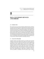
5
THE FREQUENCY MODULATED
RADIO RECEIVER
5.1 INTRODUCTION
In amplitude modulation, the frequency of the carrier is kept constant while its
amplitude is changed in accordance with the amplitude of the modulating signal. In
frequency modulation, the amplitude of the carrier is kept constant and its frequency
is changed in accordance with the amplitude of the modulating signal. It is evident
that, if a circuit could be found which will convert changes in frequency to changes
in amplitude, the techniques used for detecting AM can be used for FM as well.
In Section 4.3.3.4, three frequency-to-amplitude conversion circuits were
discussed and their performance in terms of linearity and dynamic range were
examined. It therefore follows that the FM receiver must have the same basic form as
the AM receiver. The structure of the FM receiver is as shown in Figure 5.1.
The superheterodyne technique is used in FM for the same reasons it is used in
AM; it translates all incoming frequencies to a fixed intermediate frequency at which
the filtering process can be carried out effectively.
The antenna is responsible for capturing part of the electromagnetic energy
propagated by the transmitter. The basic rules of antenna design apply but, because
in commercial FM radio the frequency of the electromagnetic energy is between 88
and 108 MHz, it is practical to have antennas whose physical dimensions are within
tolerable limits.
The radio-frequency amplifier raises the power level to a point where it can be
used in a mixer or frequency changer to change the center frequency to a lower
frequency – the intermediate frequency (IF). The mixer in conjunction with the local
oscillator translate the incoming radio frequency to an intermediate frequency of
10.7 MHz. There is nothing special about an intermediate frequency of 10.7 MHz
except that it is a relatively low frequency at which the required values of Ls and Cs
are large enough to reduce the effects of circuit strays. It is at this fixed frequency
that filtering to remove the unwanted products of the mixing process and other
143
Telecommunication Circuit Design, Second Edition. Patrick D. van der Puije
Copyright # 2002 John Wiley & Sons, Inc.
ISBNs: 0-471-41542-1 (Hardback); 0-471-22153-8 (Electronic)
Figure 5.1. The block diagram of the domestic FM receiver showing frequency ranges and bandwidths.
144
interfering signals and noise takes place. The filtered signal then proceeds to the
amplitude limiter. The need for the limiter becomes evident when one recalls that the
FM signal is usually converted into an AM signal in the discriminator before it is
detected. This means that any variation in the amplitude of the FM signal will be
superimposed on the proper signal from the discriminator and hence will cause
distortion. The amplitude limiter very severely clips the signal to a constant
amplitude and also filters out the unwanted harmonics that are produced by the
limiter. The signal then proceeds to the frequency discriminator (frequency-to-
amplitude convertor) and onto the envelope detector. The audio-frequency amplifier
raises the output of the envelope detector to a level suitable for driving a
loudspeaker.
Although the structures of AM and FM receivers are similar, there are very
important differences which require different design and construction approaches.
These are the following:
1. The higher carrier frequencies (88–108 MHz) used in FM requires small
values of both L and C in the tuned circuits used. This means that stray
inductances and capacitances will constitute a larger percentage of the
designed value and hence have a much greater effect on all tuned circuits.
Although measures can be taken to incorporate the effects of fixed circuit
strays in the design, there are other changes in element values, due to such
factors as temperature and vibration, which can cause sufficient drift to
necessitate retuning of the receiver during a program. The local oscillator is
most vulnerable to stray elements, especially because it has to operate at a
frequency 10.7 MHz above the carrier frequency. To ensure the stability of the
oscillator, high circuit Q factors, negative temperature-coefficient capacitors
and automatic frequency control (AFC) are used. Some radio-frequency
amplifiers for FM front-ends use distributed parameter circuit components
such as coaxial and transmission lines.
2. With the intermediate frequency set at 10.7 MHz, the band from which image
interference can originate is from 109.4 to 129.4 MHz. This frequency band is
reserved for aeronautical radionavigation systems. It follows that one FM
station cannot cause image interference for another but the aeronautical
radionavigation systems can. As in AM, image interference can be reduced
by differentially amplifying the desired signal relative to the image signal. A
high Q factor tuned radio-frequency amplifier is used for this purpose.
3. The use of a high Q factor tuned amplifier in the radio-frequency stage
requires a very stable local oscillator frequency which will accurately track the
incoming radio frequency and produce a minimum variation from the selected
intermediate frequency. The local oscillator by itself is not capable of this but,
used in conjunction with the AFC and other stabilizing measures, it can
perform satisfactorily.
4. The ideal intermediate-frequency filter should have a bandpass characteristic
which is flat with infinitely steep sides. The flat top is required to avoid any
5.1 INTRODUCTION 145
frequency dependent amplitude variation, the steep sides to eliminate inter-
ference from the unwanted products of the mixing process and from adjacent
channels. Two techniques, both involving a number of successive stages of
tuned circuits, are used to obtain an approximation to the ideal filter
characteristics. In the first, all the tuned circuits have the same resonant
frequency. This is known as synchronous tuning. In the second the resonant
frequencies are placed at different points in the passband. This is known as
stagger tuning.
The above qualitative as well as quantitative changes from the AM system discussed
in Chapter 3 make a separate consideration necessary.
5.2 COMPONENT DESIGN
5.2.1 Antenna
An important point to remember is that an antenna is a reciprocal device, that is, it
can be used both for transmitting signals as well as for receiving them. An antenna
structure that produces a good ground wave radiation pattern will have a good
response to the same ground wave radiation when used in the receiving mode.
Commercial FM receivers commonly use two types of antennas: the vertical whip
antenna, most commonly used with automobile radios, and the dipole and folded
dipole antennas used with other types of portable and non-portable FM radios.
Assuming that the vertical whip antenna approximates a vertical grounded
antenna, a half-wavelength antenna for the middle of the FM band will be about
1.5 m long. Such an antenna can be conveniently mounted on a vehicle. The field
patterns of vertical grounded antennas are given in Figure 2.54. It can be seen that
when the height h is less than l=2, the response is limited to the ground wave.
Commercial FM stations are designed to operate within a local area and therefore
have antennas which ensure that most of the radiated power goes into the ground
wave. An FM receiver with an antenna whose height is equal to or less than l=2 will
have a good response.
The dipole and its variation, the folded dipole, are commonly used with non-
portable FM receivers. They can be used in conjunction with directors and=or
reflectors to increase the gain of the antenna. Such an arrangement is called a Yagi–
Uda antenna.
Antenna design is beyond the scope of this text. However the interested reader is
encouraged to refer to any standard text on antennas.
5.2.2 Radio-Frequency Amplifier
The purpose of the radio-frequency amplifier is to boost the power of the incoming
signal relative to all the other signals picked up by the antenna to a level which can
be used in the frequency changer. A second function of the radio-frequency amplifier
146 THE FREQUENCY MODULATED RADIO RECEIVER
is to act as a matched load to the antenna so that the antenna signal is not reflected at
the interface leading to the loss of efficiency.
The bandwidth of an FM signal in commercial radio was calculated to be
approximately 240 kHz in Section 4.3.3.1. With a carrier frequency of about
100 MHz, the required Q factor is therefore about 400. Such a high value of Q
factor cannot normally be achieved in a simple tunable radio-frequency amplifier
and the practical approach is to use a lower Q circuit and to correct for this in the
intermediate-frequency stage that follows. An alternate technique uses a number of
stages in cascade separated by buffer amplifiers. For the superheterodyne system to
work, the local oscillator frequency must be set equal to the radio frequency plus the
intermediate frequency; for the commercial FM band, the standard intermediate
frequency is 10.7 MHz. The frequency of the local oscillator must be variable from
98.7 to 118.7 MHz. This is normally not a problem since the ratio of the high
frequency to the low frequency is only 1.2 : 1. The more important point is that the
center frequency of the radio-frequency amplifier and the frequency of the local
oscillator must maintain the difference of 10.7 MHz throughout the FM frequency
band. In the case of AM, the frequencies were low and some drift could be tolerated
without serious deterioration of the signal. In the FM system, the frequencies are
much higher and small percentage changes in one or both radio frequency and local
oscillator frequency can cause large changes in the intermediate frequency. To
overcome this problem, a system for automatic control of the frequency (AFC) of the
local oscillator is used. The basic operation is similar to that described in Section
4.3.2.
5.2.3 Local Oscillator
The local oscillator can take any of the usual oscillator forms with a bipolar
transistor as the active element. It must produce enough power to drive the mixer.
The values of the inductors and capacitors have to be chosen to minimize the effects
of circuit strays. As mentioned earlier, the local oscillator incorporates an AFC
circuit for stable tracking with the (tunable) radio-frequency amplifier.
5.2.4 Frequency Changer
The basic frequency changer was discussed in Section 3.4.3. For this application the
dual-gate FET mixer has the advantage of low leakage of the local oscillator signal
to the antenna via the radio-frequency amplifier. Such a leakage and its subsequent
radiation can cause interference with other communication and radionavigation
equipment.
5.2.5 Intermediate-Frequency Stage
The intermediate frequency for commercial FM radio is 10.7 MHz. The required
bandwidth of the filter is about 240 kHz centered at 10.7 MHz, giving a Q factor of
5.2 COMPONENT DESIGN 147
about 45. It is usual to realize the filter in two or more stagger-tuned stages with
suitable buffer amplifiers between them.
5.2.6 Amplitude Limiter
The radio-frequency amplifier, the mixer, and the intermediate-frequency amplifier,
in theory, should have a flat amplitude response in their pass bands. In practice, this
is not so. The result is that the signal emerging from the intermediate-frequency
amplifier has some variation of amplitude with respect to frequency. This is a form of
AM and it must be removed if distortion is to be avoided.
The amplitude limiter was discussed in Sections 4.3.3.1 and 4.3.3.2. It is worth
noting that sometimes the amplitude limiter is preceded by an automatic gain
control. This reduces the severity of the clipping action and hence the required signal
power and the spurious harmonics produced.
5.2.7 Frequency Discriminator
The purpose of the frequency discriminator is to convert relatively small changes of
frequency (in a very high-frequency signal) to relatively large changes in amplitude
with respect to time. The signal can then be demodulated using a simple envelope
detector which was discussed in Section 3.4.6. Two basic frequency discriminators
were discussed in Section 4.3.3.4 and these serve to illustrate the concepts. In
practice, a number of more sophisticated discriminators are used. Some of these will
now be discussed.
5.2.7.1 Foster–Seeley Discriminator. The Foster–Seeley discriminator [1,2]
is similar to the balanced slope discriminator shown in Figure 4.11. The major
difference is that it has two tuned circuits instead of three and both are tuned to the
same frequency. This is a major advantage when the receiver is being aligned. A
secondary advantage is that it has a larger linear range of operation than the slope
discriminator.
The basic circuit of the Foster–Seeley discriminator is shown in Figure 5.2.
Connected to the collector of the transistor, L
1
and C
1
are tuned to resonate at the
frequency f
o
(the intermediate frequency of the receiver). The inductance L
1
is
mutually coupled to a center-tapped inductor L
2
. The center tap is connected by a
coupling capacitor C
c
to the collector of the transistor. The inductor L
2
and C
2
are
tuned to resonate at the frequency f
o
. Two identical circuits consisting of a diode in
series with a parallel combination of a resistance and a capacitance (D
3
–R
3
–C
3
and
D
4
–R
4
–C
4
) are connected across L
2
to form a symmetrical circuit. A radio-frequency
choke (RFC – a high-valued inductance which can be considered to be an open-
circuit at high frequency but a short-circuit at low frequency) connects the center tap
to the ‘‘neutral’’ node of the D
3
–R
3
–C
3
and D
4
–R
4
–C
4
circuits.
The circuit can be divided up into two parts by the line connecting X –X
0
. The
parts of the circuit to the left of X –X
0
operate at a high frequency f
o
with a relatively
small deviation ÆDf . The circuit to the right of X –X
0
are two envelope detectors, as
148 THE FREQUENCY MODULATED RADIO RECEIVER
Figure 5.2. The Foster–Seeley discriminator. The line X –X
0
divides the circuit into high (radio) and
low (audio) frequency.
149
discussed in Section 3.2. The high-frequency input voltages to the envelope
detectors are rectified by the diodes D
3
and D
4
and the time-constants R
3
–C
3
and
R
4
–C
4
are chosen to smooth out the half-wave pulses but follow any slow changes in
the envelope (amplitude) of the half-wave pulses. These slow changes represent low
(audio) frequency.
Before proceeding to the analysis of the circuit, it is in the interest of simplicity, to
make three assumptions:
(1) The impedance of the coupling capacitance C
c
is small enough to be
considered as a short-circuit, at the frequency of operation.
(2) The impedance of the RFC is an open-circuit at the high frequency f
o
but a
short-circuit at the low (audio) frequency.
(3) The neutral node of the envelope discriminators can be considered to be
grounded since the secondary circuit, including the envelope discriminators,
is symmetric.
Now, all that needs to be demonstrated is that, when a signal of frequency f
o
Æ Df is
applied to the circuit, the amplitude of the voltage appearing across the inputs of the
envelope detectors will vary proportionally to ÆDf .
The tuned circuits L
1
–C
1
and L
2
–C
2
are both high Q factor circuits but their
mutual coupling coefficient, M, is low. This means that the secondary load coupled
into the primary circuit is negligible. The primary current is
I
1
%
V
1
joL
1
: ð5:2:1Þ
The voltage induced in the secondary is
2V
2
¼ÆjoMI
1
ð5:2:2Þ
where the Æ sign depends on the relative directions of the primary and secondary
windings. Assuming the positive sign and substituting for I
1
2V
2
¼
MV
1
L
1
: ð5:2:3Þ
Since the secondary circuit is tuned to resonance, the secondary current is
I
2
¼
MV
1
R
2
L
1
ð5:2:4Þ
where R
2
is the series resistance of the secondary circuit.
150 THE FREQUENCY MODULATED RADIO RECEIVER
The voltage across the capacitor C
2
is
2V
2
¼
I
2
jo
0
C
2
: ð5:2:5Þ
Substituting for I
2
,
2V
2
¼
MV
1
jo
0
C
2
R
2
L
1
: ð5:2:6Þ
The secondary voltage applied to one envelope discriminator is given by
V
2
¼
M
j2o
0
C
2
R
2
L
1
V
1
: ð5:2:7Þ
It is now clear that, at resonance, the primary voltage V
1
is at right angles to the
secondary voltage V
2
. The phasor diagram of the voltage applied to the inputs of the
envelope discriminators is as shown in Figure 5.3(a). This can be modified by
reversing the direction of one of the phasors representing V
2
as shown in Figure
5.3(b).
The discriminator input voltage phasors V
3
and V
4
are equal in magnitude and
since the outputs of the envelope discriminators are proportional to the magnitude of
the applied voltages, when the output is taken differentially, it is zero. This means
that the Foster–Seeley discriminator has zero volts output at the resonant frequency.
The impedance of the secondary tuned circuit, at any given frequency o,is
Z
2
¼ R
2
þ j oL
2
À
1
oC
2
: ð5:2:8Þ
Figure 5.3. (a) The basic phasor diagram of the discriminator. (b) The phasor diagram when
the FM carrier is unmodulated.
5.2 COMPONENT DESIGN 151
But at resonance
C
2
¼
1
o
2
0
L
2
: ð5:2:9Þ
Eliminating C
2
from Equation (5.2.8) gives
Z
2
¼ R
2
þ j oL
2
À
o
2
0
L
2
o
: ð5:2:10Þ
If we now define the Q factor at resonance as
Q
0
¼
o
0
L
2
R
2
ð5:2:11Þ
then Equation (5.2.10) can be written as
Z
2
¼ R
2
þ jo
0
L
2
o
o
0
À
o
0
o
: ð5:2:12Þ
Now consider relatively small changes of frequency about the resonant frequency o
o
and define ‘‘fractional detuning’’ d as
d ¼
o À o
0
o
0
ð5:2:13Þ
then
o
o
0
¼ 1 þ d ð5:2:14Þ
hence
o
o
0
À
o
0
o
¼ 1 þ d À
1
1 þ d
¼ d
2 þ d
1 þ d
: ð5:2:15Þ
For a high Q factor circuit at a frequency near the resonance, the fractional detuning
d is much smaller than 1, therefore
o
o
0
À
o
0
o
% 2d: ð5:2:16Þ
Substituting into Equation (5.2.12)
Z
2
¼ R
2
ð1 þ j2QdÞ: ð5:2:17Þ
152 THE FREQUENCY MODULATED RADIO RECEIVER
Replacing R
2
in Equation (5.2.7) by Z
2
gives
V
2
¼
M
j2o
0
C
2
L
1
R
2
ð1 þ j2Q
0
dÞ
V
1
: ð5:2:18Þ
It is evident that V
1
and V
2
are no longer at right angles to each other. The angle
between them depends on the magnitude and sign of d. When d is positive, the angle
between V
1
and V
2
is less than 90
, and when d is negative the angle is greater than
90
or vice versa. The phasor diagrams for positive and negative values of d are
shown in Figure 5.4(a) and (b), respectively.
It is clear from these that the magnitudes of the input voltages V
3
and V
4
are
unequal when d has any value other than zero. The characteristics of the Foster–
Seeley discriminator are shown in Figure 5.5.
A variation on the Foster–Seeley discriminator which combines the functions of
the amplitude limiter and frequency discriminator is called the ratio detector [3]. Its
performance however leaves much to be desired.
Figure 5.4. (a) The phasor diagram when signal frequency is lower than carrier frequency. (b)
The phasor diagram when signal frequency is higher than carrier frequency.
Figure 5.5. The amplitude–frequency characteristics of the Foster–Seeley discriminator.
5.2 COMPONENT DESIGN 153
5.2.7.2 Quadrature Detector. The basic circuit diagram of the quadrature
detector is shown in Figure 5.6. All biasing circuit components have been omitted
for clarity of its operation.
The circuit consists of a tuned amplifier Q
1
, with a very high Q factor collector
load. The input to the circuit is the output from the amplitude limiter which is a
frequency modulated square wave (i.e. a square wave of fixed frequency with
relatively small deviations in its zero crossings). Due to the high Q factor of the
tuned circuit, the output from the amplifier is a sinusoid at the fixed frequency. The
same square wave is fed to the base of Q
4
which is a constant current source for the
differential pair Q
2
–Q
3
. Therefore current flows in the differential pair only when Q
4
is switched on. The sinusoid applied to Q
2
determines what proportion of the
constant current in Q
4
flows through Q
2
as opposed to Q
3
. It can be seen from Figure
5.7(a) that, when the input signal is unmodulated, that is, when the phase difference
between the sinusoid and the square wave is fixed, the circuit can be adjusted so that
Q
2
and Q
3
conduct equal currents, giving a constant voltage across C
3
. The time-
constant R
3
C
3
hold the base of Q
5
at a dc value and the output remains constant.
When the input to the circuit is modulated, the sinusoid driving Q
2
is no longer
coincident with the square wave and Q
3
now conducts for a period proportional to
the ‘‘ phase shift’’ between the two signals. This can be seen in Figure 5.7(b). The
voltage across C
3
is a slowly varying direct current and the output is in fact the audio
frequency which was used to frequency-modulate the radio-frequency.
It should be noted that:
Figure 5.6. The circuit diagram of the quadrature detector with an emitter follower to give a low
impedance output.
154 THE FREQUENCY MODULATED RADIO RECEIVER
(1) the amplifier Q
5
provides a low output impedance for the circuit,
(2) the structure of the circuit is suitable for realization in integrated circuit form,
(3) the time-constant R
3
C
3
is chosen to ‘‘follow’’ the changes in the amplitude of
the audio-frequency signal,
(4) when the two signals are 90
out of phase (in quadrature), Q
2
and Q
3
conduct
equal currents and this condition may be used as a datum.
5.2.7.3 Phase-Locked Loop FM Detector. The phase-locked loop [4] FM
detector is the most complex of FM detectors but it has the advantage that it can be
realized in integrated circuit form where complexity is not necessarily a disadvan-
tage. The basic system is as shown in Figure 5.8.
It consists of a phase detector that generates an output signal which is propor-
tional to the difference between the phases of the two input signals (‘‘error’’ signal).
The output signal is amplified and low-pass filtered and used to control a voltage-
controlled oscillator (VCO) which usually operates at a higher frequency than the
input signal. The output of the oscillator is divided by a suitable factor N to bring it
to the same frequency as the input signal. This is the second input to the phase
detector.
Figure 5.7. (a) The phase difference between the sinusoid and the square wave when the
carrier is unmodulated is such that currents of equal magnitude flow through Q
2
and Q
3
giving a
dc output. (b) When the carrier is modulated the relative phase between the sinusoid and the
square shifts and the currents in Q
2
and Q
3
are no longer equal; the dc changes its value – the
changing dc is the audio-frequency signal.
5.2 COMPONENT DESIGN 155
The error signal fed to the VCO causes it to change frequency so that f
d
moves
closer to f
r
. When the two frequencies are close to each other, the system locks, that
is, the two frequencies become equal and their phase difference is zero. The control
voltage from the low-pass filter is then dc. When the incoming signal changes its
frequency, and hence phase, the control voltage will change its value to keep the
system in lock. The excursions of the control voltage is, in fact, the required
demodulated output.
The phase-locked loop FM detector has the advantage of having no LC tuned
circuits. In its integrated-circuit form, it requires a number of external resistors and
capacitors for its proper operation. This information is usually provided by the
manufacturer.
5.3 STEREOPHONIC FREQUENCY MODULATED RECEPTION
The baseband frequency spectrum of the stereophonic FM signal was described in
Section 4.5.2 and shown in Figure 4.25. The use of the signal to frequency modulate
a suitable carrier remains essentially the same as in the case of monophonic
transmission except for the fact that the stereophonic spectrum has a larger
bandwidth – more than three times larger. At the receiver, the signal is demodulated
and the baseband information is recovered. Figure 5.9 shows a scheme for separating
the left, LðtÞ, and right, RðtÞ, information and passing them on to their respective
loudspeakers.
The first bandpass filter has a passband 23–53 kHz and it is used to separate the
double-sideband-suppressed carrier (DSB-SC) signal which contains the left-minus-
right signal, ½LðtÞÀRðtÞ. The second bandpass filter is a narrow-band filter centered
on 19 kHz and it separates the pilot carrier. The third filter is a low-pass filter with a
Figure 5.8. The block diagram of the phase-locked loop FM detector. Note that the relatively
slow-varying dc required to keep the loop in lock is the audio-frequency signal.
156 THE FREQUENCY MODULATED RADIO RECEIVER
Figure 5.9. The block diagram of the stereophonic FM receiver showing the ideal characteristics of
the various filters required and the access point for listeners with monophonic receivers.
157
cut-off frequency of 15 kHz and it separates the left-plus-right, ½LðtÞþRðtÞ (i.e. the
monophonic) signal from the other two.
The DSB-SC signal cannot be demodulated unless the carrier is reinstated.
Because the DSB-SC signal was obtained, in the transmitter, from the pilot oscillator
followed by a frequency doubler, the process is repeated in the receiver to obtain the
carrier at 38 kHz. The carrier is then fed into the synchronous demodulator to
produce a baseband signal containing the ½LðtÞÀRðtÞ information and, after an
amplification factor of two, it is combined with the ½LðtÞþRðtÞ signal in the adder
and subtractor, respectively, to produce LðtÞ and RðtÞ.
5.3.1 Synchronous Demodulation
Synchronous demodulation of a DSB-SC signal can be achieved simply by multi-
plying the DSB-SC signal ½LðtÞÀRðtÞ cos 2o
p
t by the synchronized signal
cos 2o
p
t. The result is
vðtÞ¼½LðtÞÀRðtÞ cos
2
2o
p
t ð5:3:1Þ
vðtÞ¼
1
2
½LðtÞÀRðtÞð1 þ cos 4o
p
tÞ: ð5:3:2Þ
The required baseband signal
1
2
½LðtÞÀRðtÞ is easily separated from the signal at
4o
p
.
5.3.2 Stereophonic Receiver Circuit
Filter design is beyond the scope of this book. A list of references on filter design
can be found at the end of Chapter 3. The design of frequency multipliers was
discussed in Section 2.5. The design of the synchronous demodulator (two-input
analog multiplier) was discussed in Section 4.4.3.3. The adder=subtractor was the
subject of Section 4.4.3.5.
REFERENCES
1. Foster, D. E. and Seeley, S. W., ‘‘Automatic Tuning Simplified Circuits and Design
Practice’’, Proc. IRE., 25, 289, 1937.
2. Seeley, S. W., Radio Electronics, McGraw-Hill, New York, 1956.
3. Seeley, S. W. and Avins, J., ‘‘The Ratio Detector’’, RCA Review, 8, 201, 1947.
4. Best, R. E., Phase-Locked Loops, McGraw-Hill, New York, 1984.
5. DeFrance, J. J., Communication Electronics Circuits, 2nd Ed., Rinehart Press, San
Francisco, 1972.
6. Stark, H. and Tuteur, F. B., Modern Electrical Communications, Prentice-Hall, Englewood
Cliffs, NJ, 1979.
158
THE FREQUENCY MODULATED RADIO RECEIVER
PROBLEMS
5.1 A bipolar transistor operating at a frequency of 100 MHz has the following Y
parameters: y
11
¼ 9:84 þ j9:1; y
12
¼ 0:01 À j0:68; y
21
¼ 60:7 À j95:8 and
y
22
¼ 0:60 þ j1:8, measured in mSi in the common emitter configuration
with 0.6 V peak-to-peak appearing across the base emitter junction. Using
this device, design an oscillator to supply maximum power to a suitable
conductive load. What modifications would you make to the oscillator to
obtain a local oscillator for an FM receiver operating in the range 88–
108 MHz?
5.2 An FM receiver is tuned to a transmitter at 100 MHz. The modulation is
sinusoidal at a frequency of 15 kHz. The intermediate frequency is 10.7 MHz
and the Q factor of the intermediate-frequency amplifier is 100. Estimate the
maximum allowable drift in the local oscillator frequency, assuming that the
J
3
ðm
f
Þ terms must lie within the À3 dB bandwidth of the intermediate-
frequency amplifier.
5.3 Using the characteristics of the FET given in Figure P3.7, design an amplifier
tuned to 100 MHz with a voltage gain of 15. The dc supply voltage is 15 V and
you may allow 2 mA dc to flow through the drain. The À3 dB bandwidth
should be no larger than 250 kHz when the amplifier is connected to a second
stage whose input impedance is 250 O resistive.
5.4 Give two reasons why a double-sideband-suppressed carrier (DSB-SC) modu-
lation system is not commonly used in communication systems. Name one
communication system in which it is used, giving the relevant details.
An incoming signal in a communication receiver is given by
vðtÞ¼
1
2
b½cosðo
c
À o
m
Þt À cosðo
c
þ o
m
ÞtðP5: 1Þ
where o
c
is the carrier angular frequency and o
m
is the modulating signal
angular frequency.
What do you need to demodulate the signal and how would you carry out
the demodulation? Support your answer with suitable diagrams and derived
formulae. Can you think of a second demodulation technique for the signal?
5.5 Describe with the aid of a block diagram the superheterodyne technique for the
reception of commercial FM signals. You have an AM=FM receiver and you
wish to make changes to the configuration of the receiver by introducing a
second mixer to translate the intermediate frequency of the FM system from
the standard 10.7 MHz to the standard AM system frequency of 455 kHz.
Redesign the block diagram, giving all the necessary details to achieve your
wish. What would be the advantages and disadvantages of your new receiver?
5.6 The dual-gate FET (whose characteristics are given in Figure P5.1) is to be
used in the design of a frequency changer in a commercial FM receiver whose
PROBLEMS 159
intermediate frequency is 10.7 MHz. The output of the radio-frequency
amplifier is applied to gate 1 and it is 0.4 V peak-to-peak at a frequency of
100 MHz. The signal from the local oscillator applied to gate 2 is a square
wave whose voltage varies from þ4 V to a negative value sufficient to cut off
the drain current. Design a suitable mixer with the following specifications:
(1) direct current power supply, 12 V,
(2) average drain current, 4 mA,
(3) À3 dB bandwidth, 240 kHz.
Choose all the other values and in every case justify your choice. Calculate the
ratio of the intermediate-frequency power output to the radio-frequency power
input.
Figure P5-1.
5.7 The purpose of the discriminator in an FM receiver is to convert variation in
frequency to variation in amplitude. Describe the operation of the Foster–
Seeley discriminator and demonstrate its frequency-to-amplitude conversion
ability. What measures should be taken prior to the signal entering the
discriminator to reduce distortion and why?
160 THE FREQUENCY MODULATED RADIO RECEIVER