Điện thoại di động vô tuyến điện - Tuyên truyền Channel P1 pot
Bạn đang xem bản rút gọn của tài liệu. Xem và tải ngay bản đầy đủ của tài liệu tại đây (125.78 KB, 14 trang )
Chapter 1
Introduction
1.1 BACKGROUND
The history of mobile radio goes back almost to the origins of radio communication
itself. The very early work of Hertz in the 1880s showed that electromagnetic wave
propagation was possible in free space and hence demonstrated the practicality of
radio communications. In 1892, less than ®ve years later, a paper written by the
British scientist Sir William Crookes [1] predicted telegraphic communication over
long distances using tuned receiving and transmitting apparatus. Although the ®rst
radio message appears to have been transmitted by Oliver Lodge in 1894 [2], it was
the entrepreneur Marconi [3] who initially demonstrated the potential of radio as a
powerful means of long-distance communication. In 1895, using two elevated
antennas, he established a radio link over a distance of a few miles, and technological
progress thereafter was such that only two years later he succeeded in
communicating from The Needles, Isle of Wight, to a tugboat over a distance of
some 18 miles (29 km). Although it seems highly unlikely that Marconi thought of
this experiment in terms of mobile radio, mobile radio it certainly was.
Nowadays the term `mobile radio' is deemed to embrace almost any situation
where the transmitter or receiver is capable of being moved, whether it actually
moves or not. It therefore encompasses satellite mobile, aeromobile and maritime
mobile, as well as cordless telephones, radio paging, traditional private mobile radio
(PMR) and cellular systems. Any book which attempted to cover all these areas
would have to be very bulky and the present volume will therefore be concerned
principally with the latter categories of use, which are covered by the generic term
`land mobile radio'. This, however, is not a book that deals with the systems and
techniques that are used in land mobile communications; it is restricted primarily to
a discussion of the radio channel ± the transmission medium ± a vital and central
feature which places fundamental limitations on the performance of radio systems.
The majority of the book is concerned with the way in which the radio channel
aects the signal that propagates through it, but there are other chapters treating
related topics. These have been included to make the book more comprehensive
without straying too far from the main theme.
It is not pro®table at this point to discuss details; they can be left until later. Suce
it to say that in the vast majority of cases, because of complexity and variability, a
The Mobile Radio Propagation Channel. Second Edition. J. D. Parsons
Copyright & 2000 John Wiley & Sons Ltd
Print ISBN 0-471-98857-X Online ISBN 0-470-84152-4
deterministic approach to establishing the parameters of the propagation channel is
not feasible. Almost invariably it is necessary to resort to measurements and to the
powerful tools of statistical communication theory. One point worth clarifying at
this stage, however, is that signal transmission over a mobile radio path is reciprocal
in the sense that the locations of the transmitter and receiver can be interchanged
without changing the received signal characteristics. The discussion can therefore
proceed on the basis of transmission in either direction without loss of generality.
However, a word of caution is needed. The levels of ambient noise and interference
at the two ends of the link may not be the same, so reciprocity with respect to the
signal characteristics does not imply reciprocity with respect to the signal-to-noise or
signal-to-interference ratios.
Some years ago the primary concern of a book such as this would undoubtedly
have been the propagation aspects related to traditional mobile radio services which
are based on the concept of an elevated base station on a good site, communicating
with a number of mobiles in the surrounding area. Such systems, known as PMR
systems, developed rapidly following World War II, especially once the transistor
made it possible to design and build compact, lightweight equipment that could
easily be installed in a vehicle and powered directly from the vehicle battery. These
are often termed dispatch systems because of their popularity with police forces, taxi
companies and service organisations who operate ¯eets of vehicles. The frequency
bands used for dispatch systems lie in the range 70±470 MHz and have been chosen
because the propagation characteristics are suitable, the antennas have a convenient
size and adequate radio frequency (RF) power can be generated easily and
eciently.
The operational strategy is to divide the available spectrum into convenient
channels with each user, or user group, having access to one or more of these
channels in order to transmit a message, usually speech, by amplitude modulation or
frequency modulation. The technique of providing a service to a number of users in
this way is known as frequency division multiple access (FDMA), and because each
channel carries only one message the term single channel per carrier (SCPC) is also
used. In the early post-war days, channels were spaced by 100 kHz, but advances in
technology, coupled with an ever increasing demand for licences, has led to several
reductions to the point where currently in the UK, channels in the VHF band (30±
300 MHz) are 12.5 kHz apart, whereas 25 kHz separation is still used for some
channels in the UHF band (300±3000 MHz).
For these PMR systems, indeed for any mobile radio system with a similar
operating scenario, the major propagation-related factors that have to be taken into
consideration are the eect of irregular terrain and the in¯uence on the signal of
trees, buildings and other natural and man-made obstacles. In recent years, however,
expanded services have become available, for example radio pagers, which are now
in common use. Hand-portable, rather than vehicle-borne equipment is also being
used by security guards, police ocers and by subscribers to cellular radio-telephone
systems. Hand-portable equipment can easily be taken into buildings, so a book
concerned with propagation must also consider the properties of the signal inside
buildings and in the surrounding areas. For cordless telephones and the like, there is
also a need to study propagation totally within buildings. Neither can we restrict
attention to frequencies below 470 MHz; ®rst- and second-generation analogue and
2 The Mobile Radio Propagation Channel
digital cellular radio telephone systems, e.g. AMPS, TACS, GSM and DCS1800, use
frequencies up to 1900 MHz, and third-generation wideband systems will probably
use even higher frequencies to solve the problems of spectrum congestion and
required bandwidth.
What then are the matters of primary concern? For transmissions of the
traditional type, in which the signals are restricted to fairly narrow radio channels,
two major factors have to be quanti®ed:
. Median signal strength
. Signal variability
The ability to predict the minimum power a transmitter must radiate to provide an
acceptable quality of coverage over a predetermined service area and the ability to
estimate the likely eect of such transmissions on services in adjacent areas, are both
critical for improving frequency reuse techniques, for implementing band-sharing
schemes between dierent services and for the success of radio-telephone systems.
This is not easy and there is a vital and continuing need for a better understanding of
the in¯uence of the dierent urban and terrain factors on the mobile radio signal.
As far as signal variability is concerned, it is often convenient to separate the
eects into those which occur over a short distance and those which are apparent
only over much longer distances. Short-distance eects include the rapid fading
caused by multipath propagation in urban areas; longer-distance eects include the
much slower variations in average signal strength as the receiver moves from one
area to another.
For digital systems it is neither ecient nor desirable to use FDMA/SCPC as a
multiple-access technique, and spectrum utilisation is substantially improved by
allowing each user access to a wider-bandwidth radio channel, but only for a small
percentage of the time. This time division multiple access (TDMA) strategy is used in
the GSM and DCS1800 systems. Third-generation systems will be based around
wideband code division multiple access (CDMA) and these spread-spectrum systems
will oer even greater capacity and security together with access to multimedia
communications. First developed for military purposes, CDMA has virtually no
noise or crosstalk and is well suited to high-quality multimedia services. The
characterisation of wideband channels will be discussed in Chapter 6; for now it will
suce to note that if digital (pulse) signals propagate in a multipath environment
then interference can occur between a given pulse and a delayed version of an earlier
pulse (an echo) that has travelled via a longer path. This is known as intersymbol
interference (ISI) and can cause errors. The extent of the problem can be quanti®ed
by propagation studies which measure parameters such as the average delay and the
spread of delays.
Finally, in this introductory section, it is worth making two further points. Firstly,
the geographical service area of many mobile radio systems is too large to be
economically covered using a single base station, and various methods exist to
provide `area coverage' using a number of transmitters. We will return to this topic
in Section 1.3.2. Secondly, in order to maximise the use of the available spectrum,
channels that are allocated to one user in a certain geographical area are reallocated
to a dierent user in another area some distance away. The most common example
Introduction 3
of this is cellular radio, which relies on frequency reuse to achieve high spectrum
eciency. However, whenever frequencies are reallocated, there is always the
possibility that interference will be caused and it should therefore be understood that
adequate reception conditions require not only an acceptable signal-to-noise ratio
but also, simultaneously, an acceptable signal-to-interference ratio. This subject will
be treated in Chapter 9. Throughout the book the term `base station' will be used
when referring to the ®xed terminal and the term `mobile' to describe the moving
terminal, whether it be hand-portable or installed in a vehicle.
1.2 FREQUENCY BANDS
Having set the scene, we can now discuss some of the topics in a little more detail. It
is very important to understand how RF energy propagates and in preparation for a
brief general discussion let us de®ne more clearly what is meant by the term `radio
wave' and how waves of dierent frequencies are classi®ed. The part of the
electromagnetic spectrum that includes radio frequencies extends from about 30 kHz
to 300 GHz, although radio wave propagation is actually possible down to a few
kilohertz. By international agreement the radio frequency spectrum is divided into
bands, and each band is given a designation as in Table 1.1.
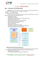
Electromagnetic energy in the form of radio waves propagates outwards from a
transmitting antenna and there are several ways in which these waves travel, largely
depending on the transmission frequency. Waves propagating via the layers of the
ionosphere are known as ionospheric waves or sky waves; those that propagate over
other paths in the lower atmosphere (the troposphere) are termed tropospheric waves,
and those that propagate very close to the Earth's surface are known as ground
waves. Ground waves can be conveniently divided into space waves and surface waves,
and space waves can be further subdivided into direct waves which propagate via the
direct path between transmitting and receiving antennas and ground-re¯ected waves
that reach the receiving antenna after re¯ection from the ground. Figure 1.1 gives a
simple picture. The surface waves are guided along the Earth's surface and because the
Earth is not a perfect conductor, energy is extracted from the wave, as it propagates, to
supply losses in the ground itself. The attenuation of this wave (sometimes known as
the Norton surface wave) is therefore directly aected by the ground constants
4 The Mobile Radio Propagation Channel
Table 1.1 Designation of frequency bands
Frequency band Frequency range
Extremely low frequency (ELF) 53kHz
Very low frequency (VLF) 3±30 kHz
Low frequency (LF) 30±300 kHz
Medium frequency (MF) 300 kHz±3 MHz
High frequency (HF) 3±30 MHz
Very high frequency (VHF) 30±300 MHz
Ultra high frequency (UHF) 300 MHz±3 GHz
Super high frequency (SHF) 3±30 GHz
Extra high frequency (EHF) 30±300 GHz
(conductivity and dielectric constant) along the transmission path. The importance of
each of these waves in any particular case depends upon the length of the propagation
path and the frequency of transmission. We can now discuss each frequency band in
turn.
1.2.1 VLF
In the VLF range the wavelength is very long, typically 10
5
m, and antennas are
therefore very large. They have to be very close to the Earth and are often buried in
the ground. The radio waves are re¯ected from the ionosphere and a form of Earth±
ionosphere waveguide exists that guides the wave as it propagates. Because of
diurnal variations in the height of the ionospheric D-layer, the eective height of the
terrestrial waveguide also varies around the surface of the Earth. The uses of VLF
include long-distance worldwide telegraphy and navigation systems. Frequencies in
the VLF range are also useful for communication with submerged submarines, as
higher frequencies are very rapidly attenuated by conducting sea water. Digital
transmissions are always used but the available bandwidth in this frequency range is
very small and the data rate is therefore extremely low.
1.2.2 LF and MF
At frequencies in the range between a few kilohertz and a few megahertz (the LF and
MF bands) ground wave propagation is the dominant mode and the radiation
characteristics are strongly in¯uenced by the presence of the Earth. At LF, the
surface wave component of the ground wave is successfully utilised for long-distance
communication and navigation. Physically, antennas are still quite large and high-
power transmitters are used. The increased bandwidth available in the MF band
allows it to be used for commercial AM broadcasting, and although the attenuation
Introduction 5
Figure 1.1 Modes of radio wave propagation.
of the surface wave is higher than in the LF band, broadcasting over distances of
several hundred kilometres is still possible, particularly during the daytime. At night,
sky wave propagation via the D-layer is possible in the MF band and this leads to
the possibility of interference between signals arriving at a given point, one via a
ground wave path and the other via a sky wave path. Interference can be
constructive or destructive depending upon the phases of the incoming waves;
temporal variations in the height of the D-layer, apparent over tens of seconds, cause
the signal to be alternatively strong and weak. This phenomenon, termed fading, can
also be produced by several other mechanisms and always occurs when energy can
propagate via more than one path. It is an important eect in mobile radio.
1.2.3 HF
Ground wave propagation also exists in the HF band, but here the ionospheric or
sky wave is often the dominant feature. For reasons which will become apparent
later, the HF band is not used for civilian land mobile radio and it is therefore
inappropriate to go into details of the propagation phenomena. Suce it to say that
the layers of ionised gases within the ionosphere (the so-called D, E and F layers)
exist at heights up to several hundred kilometres above the Earth's surface, and
single and multiple hops via the various ionospheric layers permit almost worldwide
communications. The height of the dierent layers varies with the time of day, the
season of the year and the geographical location [4]; this causes severe problems
which have attracted the attention of researchers over many years and are still of
great interest.
1.2.4 VHF and UHF
Frequencies in the VHF and UHF bands are usually too high for ionospheric
propagation to occur, and communication takes place via the direct and ground-
re¯ected components of the space wave. In these bands, antennas are relatively small
in physical size and can be mounted on masts several wavelengths above the ground.
Under these conditions the space wave is predominant. Although the space wave is
often a negligible factor in communication at lower frequencies, it is the dominant
feature of ground wave communication at VHF and UHF. The bandwidth available
is such that high-quality FM radio and television channels can be accommodated,
but propagation is normally restricted to points within the radio horizon and
coverage is therefore essentially local. The analysis of space wave propagation at
VHF and UHF needs to take into account the problems of re¯ections both from the
ground and from natural and man-made obstacles. Diraction over hilltops and
buildings, and refraction in the lower atmosphere are also important.
1.2.5 SHF
Frequencies in the SHF band are commonly termed microwaves, and this term may
also be used to describe that part of the UHF band above about 1.5 GHz.
Propagation paths must have line-of-sight between the transmitting and receiving
antennas, otherwise losses are extremely high. At these frequencies, however, it is
possible to design compact high-gain antennas, normally of the re¯ector type, which
6 The Mobile Radio Propagation Channel
concentrate the radiation in the required direction. Microwave frequencies are used
for satellite communication (since they penetrate the ionosphere with little or no
eect), point-to-point terrestrial links, radars and short-range communication systems.
1.2.6 EHF
The term `millimetre wave' is often used to describe frequencies in the EHF band
between 30 and 300 GHz. In comparison with lower frequencies, enormous
bandwidths are available in this part of the spectrum. Line-of-sight propagation is
now predominant and although interference from ground-re¯ected waves is possible,
it is often insigni®cant, because the roughness of the ground is now much greater in
comparison with the wavelength involved. It is only when the ground is very smooth,
or a water surface is present, that the ground-re¯ected waves play a signi®cant role.
This topic will be treated in Chapter 2. In the millimetre waveband the most
important eects that have to be taken into account are scattering by precipitation
(rain and snow) and, at certain frequencies, absorption by fog, water vapour and
other atmospheric gases.
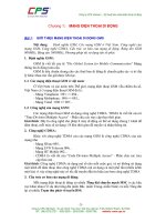
A detailed treatment of millimetre wave propagation is well beyond the scope of
this book and, in any case, is not directly relevant to current mobile radio systems.
However, Figure 1.2 shows the attenuation by oxygen and uncondensed water
vapour [5] as a function of frequency. At some frequencies there are strong
absorption lines, e.g. the water vapour absorption at 22 GHz and the oxygen
absorption at 60 GHz. However, between these lines there are windows where the
attenuation is much less. Specialised applications such as very short range secure
communication systems and satellite-to-satellite links are where millimetre waves
Introduction 7
Figure 1.2 Attenuation by oxygen and water vapour at sea level, T 208C; water
content 7.5 g/m
3
.
®nd application, although in the 1980s there was some interest in the absorption
bands as they appeared to have some potential for future microcellular systems. At
present there is no volume market in this frequency range, so component and system
costs are very high.
1.3 MOBILE RADIO FREQUENCIES
There are several factors that have to be taken into account in deciding what frequency
band should be used for a particular type of radio communication service. For the
speci®c application of interest, two-way mobile radio operations, communication is
required over ranges that do not normally exceed a few tens of kilometres, often much
less. Clearly, unnecessary interference would be caused to other users if the signals
propagated too far. It is also evident that if mobiles are to communicate freely with
their base, or with each other, throughout a given area (which may or may not be the
total service area of the system) the transmitters involved must be able to provide an
adequate signal strength over the entire area concerned.
Operating frequencies must be chosen in a region of the RF spectrum where it is
possible to design ecient antennas of a size suitable for mounting on base station
masts, on vehicles and on hand-portable equipment. Since the mobiles can move
around freely within the area covered by the radio system, their exact location is
unknown and the antennas must therefore radiate energy uniformly in all directions
in the horizontal (azimuth) plane; technically this is known as omnidirectional
radiation.* It is also vital that the frequencies chosen are such that the transmitters
used at base stations and mobiles can generate the necessary RF power while
remaining fairly small in physical size.
For two-way mobile radio, particularly in urban areas, it is seldom that the mobile
antenna has a direct line-of-sight path to the base station. Radio waves will penetrate
into buildings to a limited extent and, because of diraction, appear to bend slightly
over minor undulations or folds in the ground. Fortunately, due to multiple
scattering and re¯ection, the waves also propagate into built-up areas, and although
the signal strength is substantially reduced by all these eects, sensitive receivers are
able to detect the signals even in heavily built-up areas and within buildings. The
choice of frequency is therefore limited by the need to minimise the losses due to
buildings while continuing to satisfy the other constraints mentioned above.
For these reasons, traditional two-way mobile radio originally developed almost
exclusively around the VHF and latterly UHF bands. In a city, for example, there
are many mobile radio users such as emergency services and taxi companies. In the
case of a police force, the central control room receives reports of incidents in the city
area, often by emergency telephone calls. The control room radio operator puts out a
call to a police ocer believed to be in the appropriate area; who may be on foot
with a personal radio or in a vehicle equipped with mobile radio. On receipt of the
call, the ocer acknowledges it, investigates the incident and reports back by radio.
Because of the FDMA/SCPC method of operation, police forces have radio channels
allocated for their exclusive use and there is no mutual interference between them
8 The Mobile Radio Propagation Channel
*Omnidirectional is not to be confused with isotropic which means `in all directions'.
and other users on dierent channels in the same frequency band. However, all
police ocers who carry a receiver tuned to the appropriate frequency will hear the
calls as they are broadcast.
The range over which signals propagate is also a fundamental consideration since
in order to use the available spectrum eciently, it is necessary to reallocate radio
channels to other users operating some distance away. If, in the above example, the
message from the control room had been radiated on HF, then it is possible that the
signals could have been detected at distances of several hundred kilometres, which is
unnecessary, undesirable and would cause interference to other users. The VHF and
UHF bands therefore represent an optimum choice for mobile radio because of their
relatively short-range propagation characteristics and because radio equipment
designed for these bands is reasonably compact and inexpensive.
Vertical polarisation is always used for mobile communications; at frequencies in
the VHF band it is preferable to horizontal polarisation because it produces a higher
®eld strength near the ground [6]. Furthermore, mobile and hand-portable antennas
for vertical polarisation are more robust and more convenient to use. In an overall
plan for frequency reuse, no worthwhile improvement can be achieved by employing
both polarisations (as in television broadcasting) because scattering in urban areas
tends to cause a cross-polar component to appear. Although this may have some
advantages, for example it is often inconvenient to hold the antenna of a hand-
portable radio-telephone in a truly vertical position, it is apparent that no general
bene®t would result from the transmission of horizontally polarised signals.
There are many other services, however, which also operate in the VHF and UHF
bands, for example, television, domestic radio, Citizens' Band radio, marine radio,
aeromobile radio (including instrument landing systems) and military radio. Several
of these services have a `safety of life' element and it is vital that their use is tightly
regulated to ensure maximum eciency and freedom from interference. The exact
frequencies within the VHF and UHF bands that are allocated for various radio
systems are agreed at meetings of the International Telecommunications Union
(ITU) and are legally binding on the member states. Every twenty years the ITU
organises a world administrative radio conference (WARC) at which regulations are
revised and updated and changes in allocations and usage are agreed.
In each country, use of the radio frequency spectrum is controlled by a regulatory
authority; in the UK this is the Department of Trade and Industry (DTI) and in the
USA it is the Federal Communications Commission (FCC). The regulatory authority
is responsible for allocating speci®c portions of the available spectrum for particular
purposes and for licensing the use of individual channels or groups of channels by
legitimate users. Because of the attractive propagation characteristics of VHF and
UHF, it is possible to allocate the same channel to dierent users in areas separated
by distances of 50±100 km with a substantial degree of con®dence that, except under
anomalous propagation conditions, they will not interfere with each other.
1.3.1 Radio links
For obvious reasons, VHF or UHF radio transmitters intended to provide coverage
over a fairly large area are located at strategic points (usually high, uncluttered sites)
within the intended area. However, the control room may be at some completely
Introduction 9
dierent location, so a method has to be found to get the intended message information
(which may be voice or data) to the transmitter sites. This can be achieved by using
telephone lines or by a further radio link. The technical speci®cations for telephone
lines and the policy for their use often rule out this possibility, and the necessary quality
and reliability of service can only be achieved by using a radio link between the control
room and each of the VHF/UHF transmitter sites.
The kind of radio link used for this purpose has requirements quite dierent from
those of the two-way VHF/UHF systems used to communicate with mobiles. In this
case we are only communicating between one ®xed point (the control room) and
another ®xed point (the site concerned), and for this reason such links are commonly
termed point-to-point links. Omnidirectional radio coverage is not required, in fact it
is undesirable, so it is possible to use directional antennas which concentrate the
radio frequency energy in the required direction only. In addition, there is a
substantial degree of freedom to locate the link transmitters and receivers at
favourable locations where a line-of-sight path exists and the radio path does not
need to rely on the propagation mechanisms, discussed earlier, which make the VHF
and UHF bands so attractive for communications to and from mobiles.
These features have been exploited extensively in link planning, particularly with
regard to allocation of frequencies. Because of congestion in the frequency bands
best suited to communications with mobiles, link activity has been moved into higher
frequency bands and modern links operate typically at frequencies above 2 GHz.
This presents no problems since compact high-gain directional antennas are readily
available at these frequencies. Two frequencies are necessary for `go' and `return'
paths, since if a link serves more than one base transceiver then one may be
transmitting while others are receiving; this means that full-duplex operation is
needed, i.e. messages can pass both ways along the link simultaneously.
When several channels are operated from the same transmitter site, a choice has to be
made between using several link frequencies, one for each transmitter, or using a
multiplexed link in which the messages for the dierent transmitters at the remote site are
assembled into an FDM baseband signal which is then modulated onto the radio bearer.
The multiplex approach can be more ecient than the SCPC alternative in requiring only
one transceiver at each end of the link, and this technique is widely implemented.
Naturally, the bandwidth occupied by a multiplexed link transmission is proportionally
greater than an SCPC signal, but a 10-channel multiplexed link connection occupies no
more spectrum than 10 separate links spaced out in frequency.
Certain conditions have to be satis®ed for radio links to operate satisfactorily.
Firstly it is vital that the direct path between the two antennas (the line-of-sight path)
is clear of obstructions. However, this in itself is not enough; it is highly desirable
that there are no obstructions close to the line-of-sight path since they could cause
re¯ections and spoil reception. Figure 1.3 shows a simple link path of the kind we are
considering; the dotted line de®nes a region known as the ®rst Fresnel zone. The
theory in Chapter 2 enables us to calculate the dimensions of this zone, and shows
that for satisfactory radio link operation it should be almost free of obstructions.
1.3.2 Area coverage
A traditional mobile radio system comprises several transceivers which communicate
with a single, ®xed base station. In most cases the base station is centrally located
10 The Mobile Radio Propagation Channel
within the area to be served and is connected to the control room via a telephone
line or radio link. A straightforward approach to the problem of providing coverage
over very large areas would therefore be to erect a very high tower somewhere near
the centre of the required coverage area and install a powerful transmitter. This
technique is used by the broadcasting authorities; their transmitting masts may be
over 300 m high and they radiate signals of many kilowatts. But the broadcasting
problem has little in common with the communications problem. Broadcasting aims
to deliver a strong signal to many receivers all tuned to the same broadcast and with
no capability to transmit back. In communications a relatively small number of users
are involved in any one radio network and mobiles normally need to transmit back
to the central base station. The requirement for many user groups to use the radio
spectrum for independent and unrelated services is the dominant issue here, since
there are far too many user groups and far too little spectrum available to allocate a
unique segment of it to each group. The same frequencies therefore have to be reused
many times in dierent parts of the country.
The question is therefore, how far away from a transmitter it is necessary to go
before its frequency can be reused without risk of mutual interference in either
direction. This will be discussed in Chapter 9 but the distance is in fact quite large, at
least ®ve times the radius of the coverage area, depending on how comprehensively
the service area is provided with strong receivable signals. If a single high mast were
situated in the middle of, say, the London area with sucient transmitter power to
cover all of Greater London, then that frequency would not be reusable anywhere in
the south of England, nor in a large part of Wales.
What are the alternatives? An obvious one is to have a large number of low-power
transmitters radiating from short masts, each covering a small territory but permitting
reuse of the frequencies assigned to them many times in a de®ned geographical area.
This is the basis of the `cellular radio' approach to area coverage and is extremely
eective. However, implementing this technique requires ®rstly a large number of
available channels, and secondly a complicated and costly infrastructure [7,8].
Although this is acceptable for a high-quality nationwide radio-telephone network, it is
not attractive for a more localised PMR dispatch system.
For traditional mobile radio services, if the area is too large to be economically
covered by one base station or if geographical conditions produce diculties, a more
Introduction 11
Figure 1.3 Simple point-to-point radio link.
suitable solution is to transmit from several locations at once. In this case the
transmitters are all operated at nominally the same frequency so that whatever the
location of the mobile within the overall coverage area, it is within range of at least
one of the base stations and its receiver does not have to be retuned. This method of
operation is well established and is known as quasi-synchronous or simulcast
operation. It exploits the fact that although a transmission frequency cannot be used
for another service close to the desired coverage area because of interference, it can
be reused for the same service.
It is normal for base stations to communicate with mobiles using one frequency
(or channel) and for the mobiles to reply using another, dierent frequency; this
mode of operation is known as two-frequency simplex. To ensure a good service it is
essential to provide an adequate signal to mobiles located anywhere within the
intended coverage area of a given base station. It is impossible to cover 100% of
locations, for reasons that will become apparent later on, so in practice this
requirement amounts to covering a large percentage of locations (more than 95%).
Early attempts to operate quasi-synchronous systems using AM or FM revealed
problems in areas where transmissions from more than one site could be received
(the so-called overlap areas). For satisfactory operation it is necessary to operate the
various transmitters at frequencies a few hertz apart (hence the term quasi-
synchronous). In addition, the modulation needs to be synchronised between the
various transmitters so that in the overlap areas, where equally strong signals arrive
at the mobile from two or more transmitters, the information part of the signal is
coherent regardless of the source from which it originates. Since the message being
transmitted originates from a central control point, the synchronisation requirement
means that the time delay involved in sending the message from control to the
various transmitters in the system must be the same. In other words, all the radio
links in the system must be delay-equalised. The situation seems to be even more
critical in digital systems using the TETRA standard, which are now reaching the
implementation stage. Diculties are likely to arise as a result of timing and
synchronisation problems and to minimise such problems it is necessary for
designers to aim at truly synchronous operation of the various transmitters that
make up the area coverage system [9].
Linking all the base station transmitters and receivers to the control room may be
achieved by either ring or star connections as shown in Figure 1.4. In this type of
system there is an additional requirement associated with the way in which mobiles
communicate with `control'. In the earlier discussion of this type of operation, the
principal consideration was to ensure that the transmitter network provided an
adequate signal at a high percentage of locations. But in considering the receive
problem, it is clear that a mobile wishing to access control, transmits on a vacant
channel and a signal is received at each of the various base station sites. Usually, one
base receiver will receive a stronger signal than the others because the mobile is
nearest to the site in question.
The radio system needs to decide which site is nearest to the mobile and to
establish communications via that site. This means the system must compare the
radio signals from the mobile at all the base station receivers and then choose the
strongest. This is known as receiver voting. In the absence of other factors,
comparison of received signal strengths around a ring connection might be ecient
12 The Mobile Radio Propagation Channel
in terms of link deployment, but this type of connection involves accumulated delay
in reaching a decision on which is the `best' receiver and this delay is unacceptable in
emergency service applications. Star connections are therefore preferable.
1.4 POSTSCRIPT
In the context of mobile radio systems in general, and channel characterisation in
particular, propagation models are required to deal with a number of situations as
outlined in Section 1.1. These models are necessary for accurate coverage planning,
the characterisation of multipath eects and for interference calculations. Moreover,
they are required for a wide variety of environments from rural areas to in-building
Introduction 13
Figure 1.4 Con®guration of link networks: (a) star connection, (b) ring connection.
situations, and for special cases such as in tunnels and along railways. The overall
scenario encompasses the full range of macrocells, microcells and picocells; some
have the base station antenna well above the local clutter and others do not. In
second-generation cellular radio systems, the network planning process (Chapter 11)
includes not only coverage planning but also frequency assignment strategies and
aspects of base station parameters. Third-generation (UMTS) systems will
incorporate a hierarchical cell structure and for this, coverage planning, frequency
assignment strategies and call handover algorithms will be very important. Only
some of these aspects will be covered in the book, but they are mentioned here to
identify the complex high-level network planning process within which propagation
prediction methods have to exist.
As we will see later on, several types of database are required to underpin
propagation models. They include terrain height information, land usage data,
building shape and height information, and vegetation data. For determining
building penetration losses, the characteristics of building materials may well be
important. It is important to know the resolution and accuracy of such databases, as
well as the relationship between database accuracy and prediction accuracy.
Although a clear relationship is intuitively present, it is not immediately apparent
that the time, eort and considerable expense of acquiring and continually updating
such databases leads to predictions with an accuracy that justi®es the outlay. A
fundamental rethink of approaches to modelling ± perhaps a move away from
empirical and statistical modelling to a deterministic or semideterministic
approach ± may well be necessary before accurate, multidimensional databases
can be used to full eect. It is probably also necessary to consider how to extract
relevant information from the databases and how best to incorporate it into such
models to gain maximum advantage. It may well be helpful to read the following
chapters in that context.
REFERENCES
1. Sir William Crookes (1892) Some possibilities of electricity. Fortnightly Review, 173±81.
2. Austin B.A. (1994) Oliver Lodge ± the forgotten man of radio? Radioscientist, 5(1), 12±16.
3. Marconi Co. Ltd. (1981) Gugliemo Marconi.
4. Betts J.A. (1967) High Frequency Communications. English Universities Press, London.
5. Collin R.E. (1985) Antennas and Radiowave Propagation. McGraw-Hill, New York.
6. Knight P. (1969) Field strength near the ground at VHF and UHF: theoretical dependence on
polarisation. BBC Research Report 1969/3.
7. Appleby M.S. and Garrett J. (1985) Cellnet cellular radio network. Br. Telecommun.
Engng, 4, 62±9.
8. Department of Trade and Industry (1985) A Guide to the Total Access Communication System.
DTI, London.
9. Dernikas D. (1999) Performance evaluation of the TETRA radio interface employing
diversity reception in adverse conditions. PhD thesis, University of Bradford.
14 The Mobile Radio Propagation Channel