Verilog Programming part 2 docx
Bạn đang xem bản rút gọn của tài liệu. Xem và tải ngay bản đầy đủ của tài liệu tại đây (42.99 KB, 6 trang )
1.6 Trends in HDLs
The speed and complexity of digital circuits have increased rapidly. Designers
have responded by designing at higher levels of abstraction. Designers have to
think only in terms of functionality. EDA tools take care of the implementation
details. With designer assistance, EDA tools have become sophisticated enough to
achieve a close-to-optimum implementation.
The most popular trend currently is to design in HDL at an RTL level, because
logic synthesis tools can create gate-level netlists from RTL level design.
Behavioral synthesis allowed engineers to design directly in terms of algorithms
and the behavior of the circuit, and then use EDA tools to do the translation and
optimization in each phase of the design. However, behavioral synthesis did not
gain widespread acceptance. Today, RTL design continues to be very popular.
Verilog HDL is also being constantly enhanced to meet the needs of new
verification methodologies.
Formal verification and assertion checking techniques have emerged. Formal
verification applies formal mathematical techniques to verify the correctness of
Verilog HDL descriptions and to establish equivalency between RTL and gate-
level netlists. However, the need to describe a design in Verilog HDL will not go
away. Assertion checkers allow checking to be embedded in the RTL code. This is
a convenient way to do checking in the most important parts of a design.
N
ew verification languages have also gained rapid acceptance. These languages
combine the parallelism and hardware constructs from HDLs with the object
oriented nature of C++. These languages also provide support for automatic
stimulus creation, checking, and coverage. However, these languages do not
replace Verilog HDL. They simply boost the productivity of the verification
p
rocess. Verilog HDL is still needed to describe the design.
For very high-speed and timing-critical circuits like microprocessors, the gate-level
netlist provided by logic synthesis tools is not optimal. In such cases, designers
often mix gate-level description directly into the RTL description to achieve
optimum results. This practice is opposite to the high-level design paradigm, yet it
is frequently used for high-speed designs because designers need to squeeze the
last bit of timing out of circuits, and EDA tools sometimes prove to be insufficient
to achieve the desired results.
Another technique that is used for system-level design is a mixed bottom-up
methodology where the designers use either existing Verilog HDL modules, basic
building blocks, or vendor-supplied core blocks to quickly bring up their system
simulation. This is done to reduce development costs and compress design
schedules. For example, consider a system that has a CPU, graphics chip, I/O chip,
and a system bus. The CPU designers would build the next-generation CPU
themselves at an RTL level, but they would use behavioral models for the graphics
chip and the I/O chip and would buy a vendor-supplied model for the system bus.
Thus, the system-level simulation for the CPU could be up and running very
quickly and long before the RTL descriptions for the graphics chip and the I/O
chip are completed.
[ Team LiB ]
[ Team LiB ]
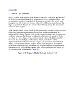
2.1 Design Methodologies
There are two basic types of digital design methodologies: a top-down design
methodology and a bottom-up design methodology. In a top-down design
methodology, we define the top-level block and identify the sub-blocks necessary
to build the top-level block. We further subdivide the sub-blocks until we come to
leaf cells, which are the cells that cannot further be divided. Figure 2-1
shows the
top-down design process.
Figure 2-1. Top-down Design Methodology
In a bottom-up design methodology, we first identify the building blocks that are
available to us. We build bigger cells, using these building blocks. These cells are
then used for higher-level blocks until we build the top-level block in the design.
Figure 2-2
shows the bottom-up design process.
Figure 2-2. Bottom-up Design Methodology
Typically, a combination of top-down and bottom-up flows is used. Design
architects define the specifications of the top-level block. Logic designers decide
how the design should be structured by breaking up the functionality into blocks
and sub-blocks. At the same time, circuit designers are designing optimized
circuits for leaf-level cells. They build higher-level cells by using these leaf cells.
The flow meets at an intermediate point where the switch-level circuit designers
have created a library of leaf cells by using switches, and the logic level designers
have designed from top-down until all modules are defined in terms of leaf cells.
To illustrate these hierarchical modeling concepts, let us consider the design of a
negative edge-triggered 4-bit ripple carry counter described in Section 2.2
, 4-bit
Ripple Carry Counter.
[ Team LiB ]
[ Team LiB ]
2.2 4-bit Ripple Carry Counter
The ripple carry counter shown in Figure 2-3
is made up of negative edge-triggered
toggle flipflops (T_FF). Each of the T_FFs can be made up from negative edge-
triggered D-flipflops (D_FF) and inverters (assuming q_bar output is not available
on the D_FF), as shown in Figure 2-4
.
Figure 2-3. Ripple Carry Counter
Figure 2-4. T-flipflop
Thus, the ripple carry counter is built in a hierarchical fashion by using building
blocks. The diagram for the design hierarchy is shown in Figure 2-5
.
Figure 2-5. Design Hierarchy
In a top-down design methodology, we first have to specify the functionality of the
ripple carry counter, which is the top-level block. Then, we implement the counter
with T_FFs. We build the T_FFs from the D_FF and an additional inverter gate.
Thus, we break bigger blocks into smaller building sub-blocks until we decide that
we cannot break up the blocks any further. A bottom-up methodology flows in the
opposite direction. We combine small building blocks and build bigger blocks;
e.g., we could build D_FF from and and or gates, or we could build a custom D_FF
from transistors. Thus, the bottom-up flow meets the top-down flow at the level of
the D_FF.
[ Team LiB ]
[ Team LiB ]
2.3 Modules
We now relate these hierarchical modeling concepts to Verilog. Verilog provides
the concept of a module. A module is the basic building block in Verilog. A
module can be an element or a collection of lower-level design blocks. Typically,
elements are grouped into modules to provide common functionality that is used at
many places in the design. A module provides the necessary functionality to the
higher-level block through its port interface (inputs and outputs), but hides the
internal implementation. This allows the designer to modify module internals
without affecting the rest of the design.
In Figure 2-5
, ripple carry counter, T_FF, D_FF are examples of modules. In
Verilog, a module is declared by the keyword module. A corresponding keyword
endmodule must appear at the end of the module definition. Each module must
have a module_name, which is the identifier for the module, and a
module_terminal_list, which describes the input and output terminals of the
module.
module <module_name> (<module_terminal_list>);
<module internals>
endmodule
Specifically, the T-flipflop could be defined as a module as follows:
module T_FF (q, clock, reset);
.
.
<functionality of T-flipflop>
.
.
endmodule
Verilog is both a behavioral and a structural language. Internals of each module
can be defined at four levels of abstraction, depending on the needs of the design.
The module behaves identically with the external environment irrespective of the
level of abstraction at which the module is described. The internals of the module
are hidden from the environment. Thus, the level of abstraction to describe a
module can be changed without any change in the environment. These levels will
be studied in detail in separate chapters later in the book. The levels are defined
below.
• Behavioral or algorithmic level
This is the highest level of abstraction provided by Verilog HDL. A module
can be implemented in terms of the desired design algorithm without
concern for the hardware implementation details. Designing at this level is
very similar to C programming.
• Dataflow level
At this level, the module is designed by specifying the data flow. The
designer is aware of how data flows between hardware registers and how the
data is processed in the design.
• Gate level
The module is implemented in terms of logic gates and interconnections
between these gates. Design at this level is similar to describing a design in
terms of a gate-level logic diagram.
• Switch level
This is the lowest level of abstraction provided by Verilog. A module can be
implemented in terms of switches, storage nodes, and the interconnections
between them. Design at this level requires knowledge of switch-level
implementation details.
Verilog allows the designer to mix and match all four levels of abstractions in a
design. In the digital design community, the term register transfer level (RTL) is
frequently used for a Verilog description that uses a combination of behavioral and
dataflow constructs and is acceptable to logic synthesis tools.
If a design contains four modules, Verilog allows each of the modules to be written
at a different level of abstraction. As the design matures, most modules are
replaced with gate-level implementations.
N
ormally, the higher the level of abstraction, the more flexible and technology-
independent the design. As one goes lower toward switch-level design, the design
becomes technology-dependent and inflexible. A small modification can cause a
significant number of changes in the design. Consider the analogy with C
p
rogramming and assembly language programming. It is easier to program in a
higher-level language such as C. The program can be easily ported to any machine.
However, if you design at the assembly level, the program is specific for that
machine and cannot be easily ported to another machine.