SolidWorks 2010- P2 potx
Bạn đang xem bản rút gọn của tài liệu. Xem và tải ngay bản đầy đủ của tài liệu tại đây (731.39 KB, 30 trang )
SoLidWorkS
®
2010
No ExpEriENcE rEquirEd
™
505434flast.indd 29 1/27/10 1:20:08 PM
505434flast.indd 30 1/27/10 1:20:08 PM
Chapter 1
Becoming Familiar
with SolidWorks
Start SolidWorks
Navigate the SolidWorks Interface
Use the CommandManager
Use and Customize the Menus
Use Toolbars
Use the Keyboard
Use the Mouse
505434c01.indd 1 1/27/10 4:54:18 PM
Chapter 1 • Becoming Familiar with SolidWorks
2
S
olidWorks 2010 is one of the most popular 3D mechanical computer-
aided design (CAD) packages on the market today. Since its introduc-
tion in 1995, SolidWorks has become a favorite design tool for many of
today’s engineers, mechanical designers, and industrial designers. In part
because of its easy-to-learn graphical user interface and powerful set of tools,
SolidWorks is used by many top companies worldwide to design, engineer, and
document their products in a variety of fields.
At the core of SolidWorks is the ability to create parametric 3D solid geometry that
is then used to create drawings, manufacturing instructions, instruction manuals,
animations, full-color renderings, and other types of documentation. Regardless of
the complexity of the item being created, the creation process is easy and follows the
same basic steps. First a sketch is created that is turned into a base feature. The base
feature is then further refined by adding features that add or remove material from
the base feature. Individual part models can then be used to build assemblies that
represent the final design. After creating the 3D part or assembly models, drawings
are made to document the design and manufacturing process.
Learning a new CAD package can be a daunting task. In addition to the
new terminology, first-time users may feel a bit overwhelmed with a new user
interface, toolbars, and commands. In this chapter, you will spend some time
launching SolidWorks for the first time, becoming familiar with the SolidWorks
interface, and working with the CommandManager.
Start SolidWorks
Before installing and running SolidWorks for the first time, ensure that you
meet the recommended minimum system requirements. SolidWorks currently
supports the following operating systems:
Windows 7 (32-bit) Professional, Ultimate or Enterprise Edition.
Windows 7 (64-bit) Professional, Ultimate or Enterprise Edition.
Windows Vista (64-bit) Ultimate, Business, or Enterprise edition, SP0
or newer
Windows Vista (32-bit) Ultimate, Business, or Enterprise edition, SP0
or newer
Windows XP Professional (32-bit), SP2 or newer
Windows XP Professional (64-bit)
505434c01.indd 2 1/27/10 4:54:18 PM
Start SolidWorks
3
And here are the random-access memory (RAM) requirements:
Minimum 1GB RAM when parts contain fewer than 200 features and assem-
blies contain fewer than 1,000 components
Recommended 2GB RAM or more when parts contain more than 200 features
and assemblies contain more than 1,000 components
Once you have verified that your computer is able to support SolidWorks
and it is installed onto your system, you can launch it by selecting Start
➢
Programs
➢ SolidWorks 2010 ➢ SolidWorks 2010 SPX.X ➢ SolidWorks 2010.
NOte
All images in this book are from SolidWorks running on Windows 7.
You might notice a slight difference if you are using another version of windows
such as Windows XP.
SolidWorks License Agreement
The first time you launch SolidWorks, you will be presented with the
SolidWorks License Agreement. You must accept the license agreement in
order to use SolidWorks. After reading the license, click Accept to continue.
If for some reason you do not accept the terms of the license agreement,
clicking Do Not Accept will exit SolidWorks.
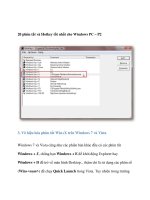
Help and Workflow Customization
After accepting the SolidWorks License Agreement, you will then be presented
with the Welcome To SolidWorks window. This screen allows you to custom-
ize the appearance of dynamic help as well as the workflow. You will see this
only the first time you launch SolidWorks on your computer, but you can make
changes to the options anytime you want in the SolidWorks Options window.
Three options are available in the Help Customization section of the screen.
Each option will provide the user with a different level of dynamic help, so con-
sider your needs when making your selection.
I Am A New User. Show Quick Tips To Help Me Get Started. This option will
provide you with pop-up messages that appear while working in different modes
of SolidWorks.
I Am New To This Version Of SolidWorks. Show Me Interactive What’s New Help.
Experienced SolidWorks users will find this option helpful when they are working
505434c01.indd 3 1/27/10 4:54:18 PM
Chapter 1 • Becoming Familiar with SolidWorks
4
in a new version of SolidWorks. When this option is selected, a question-mark icon
will be displayed on new menu items and new and changed PropertyManagers and
will link to the corresponding sections of the What’s New manual. The topics in the
What’s New manual will then provide more information about the new or updated
functionality since the previous release.
Do Not Show Me Any Dynamic Help. For more experienced users, this option
will not provide you with any pop-ups or links to the What’s New manual while
working in SolidWorks.
NOte
As you become more familiar with working in SolidWorks,
you may decide to disable the Quick Tips. You can disable them by select-
ing Help ➢ Quick Tips or by clicking the question-mark icon in the sta-
tus bar. After becoming familiar with the updates made to the new release
of SolidWorks, you can disable the display of the link by selecting Help ➢
Interactive What’s New.
The Workflow Customization section of the Welcome To SolidWorks window
allows you to hide and display tools, links, and menus items based on your usage
of SolidWorks. You can select one, two, all, or none of the following categories:
Machine Design
Mold Design
Consumer Product Design
When you select an option in the Workflow Customization section of the win-
dow, the following changes will occur in your part document environment:
Machine Design The Machine Design Overview, Machine Design Tutorials,
and SolidWorks SimulationXpress links will be displayed on the SolidWorks
Resources tab of the task pane. Sheet Metal and Weldments tabs will be added
to the CommandManager. The Molds menu item will be hidden in the Insert
menu. Draft Analysis, Undercut Detection, and Deviation Analysis will also be
hidden in the Tools menu.
Mold Design The Mold Design Overview, Mold Design Tutorials, and Import File
links will be displayed on the SolidWorks Resource tab of the task pane. Surfaces
and Molds tabs will be added to the CommandManager. The Weldments menu item
will be hidden in the Insert menu.
Consumer Product Design A Consumer Product Tutorials link will be displayed
on the SolidWorks Resources tab of the task pane. The Surfaces tab will be added
to the CommandManager. The Weldments menu item will be hidden in the Insert
menu. The Undercut Detection menu item will be hidden in the Tools menu.
505434c01.indd 4 1/27/10 4:54:18 PM
Navigate the SolidWorks Interface
5
NOte
You can adjust your workow customization at any time while in
a part file by selecting Tools ➢ Customize and select the Options tab. In the
Work ow Customization section, select or deselect the appropriate options.
For the sake of the project being demonstrated in this book, in the Welcome
To SolidWorks window select the following:
1. In the Help Customization section, select Do Not Show Me Any
Dynamic Help.
2. In the Work flow Customization section, select Consumer Product
Design, Machine Design, and Mold Design.
3. Click OK.
Navigate the SolidWorks Interface
Before using SolidWorks, you should become familiar with the layout of the
user interface. Each of the three document types in SolidWorks (parts, assem-
blies, and drawings) has the same basic interface with a few minor differences.
To start, we will examine the common elements of the three document types.
Figure 1.1 shows the SolidWorks interface when you have a part model open.
Graphics Area
The place where all the action takes place in SolidWorks is the graphics area. Here
you will be modeling your parts, putting together your assemblies, and creating
your drawings. You will be exploring this area in a lot more detail in Chapter 2,
“Learning the Basics,” when we cover the three document types in more detail.
505434c01.indd 5 1/27/10 4:54:18 PM
Chapter 1 • Becoming Familiar with SolidWorks
6
CommandManager Menu Bar Heads-up View Toolbar
Task Pane
Icons
Graphics
Area
Status BarFeatureManager Design Tree
FIGURE 1.1 SolidWorks 2010 user interface
Heads-up View Toolbar
At the top of the graphics area is the Heads-up View toolbar. This transparent
toolbar is always available at the top of your graphics area, giving you quick and
easy access to the tools necessary to manipulate your views. Icons that display
a small downward-pointing arrow provide you with more tools in a flyout, as
shown in Figure 1.2.
FIGURE 1.2 Flyout menu showing additional tools
As you become more comfortable in SolidWorks, you may discover that the tools
available on the Heads-up View toolbar may not be what you use most often. The
505434c01.indd 6 1/27/10 4:54:19 PM
Navigate the SolidWorks Interface
7
view tools shown by default are not the only tools that are available for the toolbar.
To customize the Heads-up View toolbar, do the following:
1. Right-click any of the buttons shown in the Heads-up View toolbar,
and select Customize from near the bottom of the menu.
2. Select the Commands tab at the top of the Customize window.
3. In the Categories section of the window, locate your desired tool set.
For this example, select Standard Views in the Categories section.
The tools included in the selected category will be displayed in the
Buttons section, as shown in Figure 1.3.
FIGURE 1.3 Commands tab in the Customize window
4. Drag the desired button in the Customize window to the top of the
Heads-up View toolbar. When the mouse pointer changes to include a
green plus, drop the button there.
NOte
The Heads-up View toolbar can be hidden in SolidWorks 2010.
To hide the toolbar, right-click any button in the toolbar, and deselect View
(Heads-Up) in the menu.
505434c01.indd 7 1/27/10 4:54:19 PM
Chapter 1 • Becoming Familiar with SolidWorks
8
Status Bar
Along the bottom of the SolidWorks interface is the status bar. As the name
suggests, the status bar will give you information about the actions you are per-
forming in SolidWorks. The status bar can be turned off in the View menu, but
we strongly recommend leaving it on since it can prove to be extremely useful
while you work. Here are some examples of the information that you can find in
the status bar:
As you hover over a tool, the status bar will often provide you with a
better description than what the tooltips will normally provide (see
Figure 1.4). When you become familiar with the icons for the various
tools in SolidWorks, you will require this information less often.
FIGURE 1.4 Additional tool information displayed in the status bar
Selecting on an edge, point, or any combination of these will display
basic measurements for quick reference, as shown in Figure 1.5. This
should not replace the Measure tool, but it can be extremely helpful
when you are just looking for a quick idea of the distance between
two edges.
FIGURE 1.5 Quick way to show measurements in the status bar
As you work in a sketch, the coordinates for your mouse pointer loca-
tion will be displayed as well as the status of your sketch. The sketch
status will be displayed as Fully Defined, Over Defined, Under Defined,
505434c01.indd 8 1/27/10 4:54:19 PM
Navigate the SolidWorks Interface
9
No Solution Found, or Invalid Solution Found. We will be covering
what each of these means later when we start working sketches.
Task Pane
On the right side of the graphics area is the task pane. The task pane is a set of win-
dows that provides a number of resources in one location. Normally, the task pane
is hidden, and the tab icons are the only thing visible in the graphics area. This
is probably the best option since real estate in your graphics area is very valuable.
However, if you prefer to have the task pane always open, you can do the following:
1. Click any of the task pane tab icons.
2. On the top right of the task pane, click the pushpin icon to “pin open”
the task pane (see Figure 1.6).
3. The graphics will adjust to make room for the task pane, and it will
remain open even as you click elsewhere in SolidWorks.
4. To set the task pane to autohide once again, click the pushpin icon.
FIGURE 1.6 Pinning the task pane open and hiding it again
505434c01.indd 9 1/27/10 4:54:19 PM
Chapter 1 • Becoming Familiar with SolidWorks
10
In addition to be being docked on the right side of the graphics area, the task
pane can also be floated. This is especially useful if you are working with dual
monitors. We often find it is helpful to float the task pane onto a second monitor
and pin it open. To float your task pane, do the following:
1. Click any task pane tab icon to open the task pane.
2. Drag the title bar away from the right side of the graphics area.
3. Release the left mouse button.
4. To redock the task pane, click and hold the title bar of the task pane
with the left mouse button, and drag the task pane back to the right
side of the screen. The task pane will snap back into place when the
correct position is reached.
Now we’ll take you through all the parts of the task pane.
tIp
Double-clicking the title bar of the task pane when it is docked will
return it to its previously floated position, and double-clicking the title bar
while the task pane is floating will return it to its docked position.
SolidWorks Resources
The SolidWorks Resources tab of the task pane gives you quick access to com-
mon tasks such as creating a new document, opening an existing document, and
using online tutorials. Additionally, users can get to the SolidWorks customer
portal, user forums, workflow-specific tutorials, manufacturers’ websites, and
even view the Tip of the Day. Often, the SolidWorks Resources tab is overlooked
by users, which is a shame because it gives you access to a wealth of information
in one place. Figure 1.7 shows the entire SolidWorks Resources tab.
Design Library
The Design Library tab usually points to a location on the local PC that is used to
store common reusable items such as parts, assemblies, and sketches. Documents
that are located in the Design Library can easily be added to the active document
by dragging and dropping. Figure 1.8 shows the Design Library tab of the task
pane with the menu options collapsed.
505434c01.indd 10 1/27/10 4:54:19 PM
Navigate the SolidWorks Interface
11
FIGURE 1.7 SolidWorks Resources tab of task pane
FIGURE 1.8 Design Library tab of task pane
File Explorer
The File Explorer tab gives you access to your files on your local PC and network
just like Windows Explorer, as shown in Figure 1.9.
505434c01.indd 11 1/27/10 4:54:19 PM
Chapter 1 • Becoming Familiar with SolidWorks
12
FIGURE 1.9 File Explorer tab of task pane
You can adjust the folders shown in the File Explorer on the System Options
tab, as described in the following steps:
1. Click the Options button in the menu bar.
2. On the Systems Options tab, select File Explorer.
3. Select the folders you want to be displayed in the File Explorer tab.
4. Deselect the folders that you want to be hidden in the File Explorer tab.
5. Click OK to accept your changes.
Search
Searches that are performed in the Search Assistant in the menu bar are dis-
played on the Search tab. Searches performed in SolidWorks are faster than most
search engines because the searching is done on indexed files, and SolidWorks
does not have to go digging through your PC to find a file. When SolidWorks was
installed, the Windows Desktop Search was also installed to create the index of
your files. This index should have been created after installation; if not, it will be
created the first time you do a search.
From within SolidWorks, you can quickly search for files by a full-text search,
advanced search, keywords, or retrieval of all types of documents. One of the
most common searches you will perform will probably be a keyword search. To
perform a keyword search, do the following:
1. Click in the SolidWorks search tool on the menu bar.
505434c01.indd 12 1/27/10 4:54:20 PM
Navigate the SolidWorks Interface
13
2. Type the text or keywords for your search criteria.
3. Press Enter.
All the files that match your search criteria will be displayed in the
Search tab of the task pane, as demonstrated in Figure 1.10. If the
search returns more files than what can be displayed on one screen
of the Search tab, you can navigate through the results.
FIGURE 1.10 Search tab of task pane
4. To move to the next screen, click the blue right-pointing arrow, or
click Next at the bottom of the Search tab (see Figure 1.11).
5. To return to a previous screen, click the blue left-pointing arrow.
6. To jump to a specific page, select the page number at the bottom of
the tab.
FIGURE 1.11 Scrolling through search results in task pane
View Palette
The View Palette tab contains images of standard views, section views, annota-
tion views, and flat patterns that can be dragged into a drawing, as shown in
505434c01.indd 13 1/27/10 4:54:20 PM
Chapter 1 • Becoming Familiar with SolidWorks
14
Figure 1.12. The View Palette tab displays available drawing views when you create
a drawing from a part or assembly, browse to a document from the View Palette
tab, or select a document in the list of open documents from the View Palette tab.
FIGURE 1.12 View Palette tab of task pane
Appearances/Scenes
The Appearances/Scenes tab contains appearances that you can add to your
models without actually adding the physical properties of the selected material
to your part, as shown in Figure 1.13. By dragging from the Appearances tab,
you can drop the material likeness onto your models to give them the look of
metal, plastic, glass, and other material types. In Scenes, you can also change
the environment in your models with different backgrounds and lighting
schemes. We will be covering appearances and scenes in later chapters.
Custom Properties
The Custom Properties tab, shown in Figure 1.14, provides you with a quick way
to input custom properties for the active document. Before the Custom Properties
tab can be used to update the properties for your documents, the property page
must be built, usually by an administrator. We will be covering custom properties
for parts, assemblies, and drawings in later chapters.
505434c01.indd 14 1/27/10 4:54:20 PM
Navigate the SolidWorks Interface
15
FIGURE 1.13 Appearances/Scenes tab in the task pane
FIGURE 1.14 Custom Properties tab in the task pane
Menu Bar
At the top of the screen is the ribbon-style menu bar, shown in Figure 1.15. The
menu bar provides quick access to the most common actions including creating,
opening, saving, and printing documents.
If you are familiar with previous versions of SolidWorks, you may notice the lack
of pull-down menus. Not to worry, they are still there for the times you need them.
505434c01.indd 15 1/27/10 4:54:20 PM
Chapter 1 • Becoming Familiar with SolidWorks
16
If you hover over the SolidWorks logo on the left side of the menu bar, the menu
items will fly out. Nearly all SolidWorks commands are available in these pull-down
menus, but some menus and menu items will only be available depending on the
active document type.
FIGURE 1.15 SolidWorks menu bar
CommandManager
The CommandManager by default is located below the menu bar and is a context-
sensitive toolbar, as shown in Figure 1.16. Context-sensitive means that the toolbar
will update based on the toolbar you want to utilize and will be also updated based
on the active document type. We will be discussing the CommandManager in
more detail in the upcoming “Use the CommandManager” section.
FIGURE 1.16 CommandManager
FeatureManager Design Tree
To the left of the graphics area you will find the FeatureManager design tree,
shown in Figure 1.17. The FeatureManager acts as a time machine, of sorts, by
providing you with an outline view of the history of the construction of a part or
assembly. You can use it to view the various sheets and views in a drawing. We
will be spending some time on the FeatureManager design tree in later chapters.
Toolbars
Just like in all Windows-based programs, toolbars contain most of the tools avail-
able in SolidWorks. Each toolbar is named for the functions of the tools that are
contained such as surfacing, mates, sketch tools, and so on. Figure 1.18 shows an
example toolbar. Toolbars can be floated anywhere within the SolidWorks border
or docked to the sides. Even though there are many toolbars at your disposal, we
505434c01.indd 16 1/27/10 4:54:20 PM
Use the CommandManager
17
will be showing you a technique that virtually eliminates the need for toolbars
in SolidWorks by using the CommandManager, shortcut bars, mouse gestures,
menus, and in-context toolbars.
FIGURE 1.17 FeatureManager design tree
FIGURE 1.18 A SolidWorks toolbar
Use the CommandManager
The CommandManager was introduced in SolidWorks 2004 to mixed reviews.
Since then, the CommandManager has evolved into the powerful tool you see
today. The CommandManager plays a central role in the creation of SolidWorks
documents by dynamically updating the tools based on the toolbar you are access-
ing. Depending on the document type you are editing, the tabs shown below
505434c01.indd 17 1/27/10 4:54:20 PM
Chapter 1 • Becoming Familiar with SolidWorks
18
the CommandManager will display the toolbars that are related. For example,
when you are working in a part document, the CommandManager will display the
Features, Sketch, Evaluate, and DimXpert tabs by default. However, when you are
working in a drawing, the CommandManager will display only the View Layout,
Annotation, Sketch, and Evaluate tabs.
Using the CommandManager couldn’t be any easier. Instead of hunting down
a particular toolbar, simply click the tab that corresponds to the set of tools you
require, and click the desired tool. In some cases, the CommandManager will
attempt to eliminate the number of clicks required by activating the tab that
corresponds with the environment you are working in.
Access the CommandManager
If you find yourself sitting at an installation of SolidWorks that has the
CommandManager turned off, don’t try to fumble your way through; turn it
back on. You can turn the CommandManager on using one of the following
two techniques:
Right-click the menu bar, and select CommandManager from the
very top of the menu, as shown in Figure 1.19.
FIGURE 1.19 Accessing CommandManager from the menu bar
Hover or click the SolidWorks logo on the left side of the menu bar
to make the Tools menu visible; then select Tools ➢ Customize ➢
Enable CommandManager.
Float and Dock the CommandManager
Prior to SolidWorks 2009, the CommandManager wasn’t able to be moved from
below the menu bar but now it can be floated or even docked on a different side
of the SolidWorks window. Here’s how:
1. With the mouse, select the CommandManager with the left mouse
button where no tool is present and drag the CommandManager from
its original location down to the graphics area (See Figure 1.20).
505434c01.indd 18 1/27/10 4:54:21 PM
Use the CommandManager
19
FIGURE 1.20 Floating and docking the CommandManager
tIp
Double-clicking the CommandManager when it is docked will make
it float. Double-clicking the CommandManager when it is floating will return
it to its last docked position.
2. If you release the mouse button while the CommandManager is in the
middle of the SolidWorks window, it will “float” where placed. This can
be extremely useful if you prefer to have the CommandManager close
to your working area.
3. If you click the Auto Collapse button on the upper-left corner of the
CommandManager, the buttons will disappear when it loses focus. A
small box with the title will be the only thing showing.
4. To show the buttons available in the CommandManager once again,
simply move the mouse pointer over the title of the CommandManager
once again.
505434c01.indd 19 1/27/10 4:54:21 PM
Chapter 1 • Becoming Familiar with SolidWorks
20
If you prefer, you can also dock the CommandManager on one side of the
SolidWorks window by following these steps:
1. Select the title bar of the CommandManager, if floating, or select the
docked CommandManager.
2. Drag the CommandManager over to one of the three available dock-
ing icons, as shown in Figure 1.21.
FIGURE 1.21 Docking the CommandManager to one side of the
SolidWorks window
3. With the mouse pointer over the docking icon, release the left mouse
button. The CommandManager will now be docked on the side of the
window selected.
Hide Text in the CommandManager
When you begin to become familiar with the graphical icons of the tool buttons,
you will no longer need the assistance of the text shown in the CommandManager.
Hiding the text on the CommandManager will give you more space in your
SolidWorks window for working in the graphics area. To hide the text on the
CommandManager, do the following:
1. Right-click any spot on the CommandManager.
2. In the menu, deselect the Use Large Buttons With Text option.
3. The CommandManager will change to the smaller, less intrusive
version.
505434c01.indd 20 1/27/10 4:54:21 PM
Use the CommandManager
21
Customize the CommandManager
The CommandManager, by default, has most of the toolbars and tools that you
would require for your daily usage of SolidWorks. If you select the workflow
options that apply to how you intend on using SolidWorks, additional toolbars
will be available to you. However, as you begin using SolidWorks and start explor-
ing more tools, you may discover that there are toolbars or tools that you tend to
use more often, and therefore you’ll want to add them to the CommandManager.
Add Tabs to the CommandManager
The first and quickest modification you can make to the CommandManager is
adding tabs. Say, for instance, you find yourself using more surfacing tools, and
you think it would be great to have these tools available in the CommandManager.
Here is what you do:
1. Right-click any of the tabs in the CommandManager, and you will
see all the currently available tabs that can be added, as shown in
Figure 1.22. The items shown that have a check mark are currently
in the CommandManager, and you can add the items without a
check mark.
FIGURE 1.22 Adding tabs to the CommandManager
2. To add an item to the CommandManager, click an item in the list
that does not have a check mark. The item will now have a check
mark and be added to the CommandManager.
3. To remove an item from the CommandManager, click an item with
a check mark. The check mark will disappear, and the tab will be
removed from the CommandManager.
505434c01.indd 21 1/27/10 4:54:21 PM
Chapter 1 • Becoming Familiar with SolidWorks
22
Add Existing Toolbars to the CommandManager
There may be instances where you want to add a tab that is not listed in the
right-click menu. No worries, you can add any toolbar that is available in
SolidWorks to the CommandManager. Here’s how:
1. Right-click any of the tabs on the CommandManager.
2. Select Customize CommandManager from the menu.
3. To the right of the tabs displayed in the CommandManager, click the
New Tab button.
4. Select an available toolbar listed in the menu. The new tab will be added
to the CommandManager, as shown in Figure 1.23 (Quick Snaps).
FIGURE 1.23 A new tab added to the CommandManager
The new tab will be available only in the document type you are
currently editing. For instance, if you added a new tab while in a part
document, the new tab will not be shown while editing a drawing or
assembly.
It is possible to make the new tab available in the other document types while
still customizing CommandManager by following these steps:
1. Right-click the newly created tab.
505434c01.indd 22 1/27/10 4:54:21 PM
Use the CommandManager
23
2. Select either Copy Tab To Drawings or Copy Tab To Assemblies.
NOte
If you are adding a new tab to a drawing or an assembly, the
option to copy the newly created tab to parts will also be available.
3. Once you are finished making modifications to the CommandManager,
click OK in the Customize window, shown in Figure 1.24.
FIGURE 1.24 Customize window
Create a Custom Tab
One of our favorite features of the CommandManager is the ability to create a
custom tab that can be used to create a group of some of your favorite tools.
This can prove to be especially useful if you have a set of common tasks and you
want to minimize the number of mouse clicks when selecting tabs. The first
thing you will need to do is create a new empty tab on the CommandManager:
1. Enter the customize mode for the CommandManager as discussed in
the previous section, and click the New Tab button.
505434c01.indd 23 1/27/10 4:54:21 PM