Molecular Biology Problem Solver 9 docx
Bạn đang xem bản rút gọn của tài liệu. Xem và tải ngay bản đầy đủ của tài liệu tại đây (110.5 KB, 10 trang )
you can reduce the amount of time redoing experiments, if a
problem is found.
How Can You Monitor the Performance of a Pipette?
All of the internal components of the pipette must be tested to
determine that they are fully functional.The first thing that should
be checked is the free movement of the piston. The piston should
move up and down very smoothly. Next, verify that the internal
parts are working properly by performing a leak test. Although
this test does not measure accuracy and reproducibility, it is a
quick and easy determination of the proper functioning of the
internal parts. Please remember that this type of test will only
ensure that the internal parts of the pipette are not contributing
to a leak in the pipette or tip system. It does not test if the pipette
is delivering the specified volume set on the volume display. Two
methods to detect leaks are described below. These tests are
appropriate for pipetted volumes greater than 10ml; smaller
volumes do not displace a sufficient amount of air to visually
check the performance of the pipette.
How to Properly Use and Maintain Laboratory Equipment 71
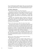
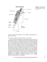
Figure 4.8 Pipette anatomy.
Reproduced with permission
from Brinkmann
TM
Instru-
ments, Inc.
The first, and easiest, approach is to set the pipette to the
maximum rated volume, attach a pipette tip, aspirate liquid into
the pipette tip, and hold the pipette in a vertical position for 15
seconds. If the liquid does not drip out, the fit of the seals and O-
rings around the piston is good and there is no need to replace
them.A leak will appear as a droplet on the pipette tip, which indi-
cates that the pipette needs to be serviced.
A second method is to monitor the stability of a column of
liquid in an attached 20 cm segment of PVC tubing. Hold the
pipette vertically, aspirate the liquid (colored liquid can be used)
and mark the meniscus level on the tubing. Wait one minute, then
check if the meniscus level has changed. If a change in the level
occurs, a leak exists and the pipette should be serviced. (Eppen-
dorf SOP Manual, p. 26.) If the tubing is connected directly to the
pipette, the internal parts are tested but not the interaction of the
pipette and tip. Testing the direct connection to the pipette and
then testing the pipette and tip connection ensures that internal
parts are not leaking and that the tip is not causing any leaks. The
size of the tubing depends upon the volume of the pipette to be
checked.
Pipette Volume Tubing Inner Diameter (mm)
10–100 ml 0.5–1
100–500 ml 1.5–2
>500 ml 5
How Can You Check If a Pipette Is Dispensing
Accurate Volumes?
Gravimetric testing of pipettes refers to the technique of weigh-
ing a dispensed amount of liquid, changing the weight to a volume,
and then determining if the volume is within the manufacturer’s
stated specifications. This is the most accepted form of testing the
volume delivery of a pipette.
According to the Eppendorf standard operating procedure for
pipette calibration, the following information details the equip-
ment, the actual procedure, and the mathematical calculations
needed to determine if the pipette is within the factory stated
calibration specifications.
The following components are required for a measuring station
for calibrating or adjusting pipettes:
1. Fine balance (tested by Board of Weights and Measures;
e.g., Sartorius
®
, Mettler
®
, Ohaus
®
, or AnD). The resolution of the
72 Troutman et al.
How to Properly Use and Maintain Laboratory Equipment 73
balance depends on the volume of the pipette that is to be
tested. The lower the volume, the better the resolution of the
balance needs to be. The balance should be located in an area
that is free of drafts and vibrations.
Nominal Volume of Error Limits of Required Accuracy
Pipette (ml) Device to Be to Be Tested (g)
Tested (ml)
1–50* 0.1–1.0 0.00001
100–1000 1.0–10 0.0001
>1000 >10 0.001
2. Evaporation protection. A moisture trap or other equip-
ment that prevents evaporation, such as a narrow volumetric
flask, are recommended for use. In addition to the narrow
weighing vessel, it is advisable to use a moisture trap within the
balance. This can be as simple as placing a dish filled with
approximately 10 ml of distilled water within the balance. For
pipettes with a maximum volume of 5000 ml and above, a mois-
ture trap is not needed.
3. Room Temperature. Ambient temperature should be 20° to
25°C, ±0.5°C during measurement. Factors that affect the tem-
perature of the pipettes and measuring station (e.g., direct sun-
light) should be avoided. The ambient temperature and the
temperature of the test liquid and pipettes must be the same as
the temperature of the pipette tip. For example, if the sample is
at 4°C and the pipette is at room temperature (22°C), this could
result in a maximum error of -5.4% (Eppendorf catalog 2000,
p. 161). It is advisable to equilibrate all components for approx-
imately three to four hours prior to calibration.
4. Test Liquid. Degassed, bi-distilled, or deionized water which
is at room temperature (20–25°C) should be used. The water
in the liquid supply or in the weighing vessel must be changed
every hour and must not be reused. The air humidity
over the liquid surface of the weighing vessel should be
maintained at a uniform value between 60% and 90% of the
relative humidity.
*For volumes <1 ml, the balance is set with six decimal places, or
where appropriate, a photometric test may be used.
5. Instruction Manual. In view of the many different types of
volume measuring devices, it is particularly important to refer
to the manufacturer’s instruction manual during testing.
6. Test Points. The number of test points is determined by the
standard that is used.As a rule of thumb, a quick check involves
4 test points, a standard check involves approximately 8 test
points, and a full calibration can involve 20 or more test points
at each volume.
7. Test Volumes. Most standards test adjustable-volume
pipettes at the following three increments:
a. The nominal volume (the largest volume of the pipette)
b. Approximately 50% of the nominal volume
c. The smallest adjustable volume, which should not be less
than 10% of the nominal volume
When testing fixed-volume pipettes, only the nominal volume is
tested. When testing multiple-channel pipettes, the same volumes
are tested for each channel.
Perform The Gravimetric Test
1. Weigh the samples:
• Tare the balance.
•
Pre-wet the tip.
• Aspirate and then dispense the set volume three times.
Execute blow-out.
2. Aspirate the volume that is to be tested from the liquid
supply as follows:
• Hold the pipette vertically in the liquid supply.
• Immerse the tip approximately 2 to 3 mm into the test liquid.
• Aspirate the test volume slowly and uniformly. Observe the
waiting period of one to three seconds.
• Remove the pipette tip from the test liquid slowly and uni-
formly. Remove any remaining liquid by placing the pipette
tip against the inside of the vessel.
3. Dispense the test volume into the weighing vessel as follows:
• Place the filled tip at an angle of 30° against the inside of the
weighing vessel
• Dispense the test volume slowly and uniformly up to the first
stop (measuring stroke) and wait for one to three seconds.
(This applies to manual pipettes only.)
74 Troutman et al.
How to Properly Use and Maintain Laboratory Equipment 75
• Press the control button to the second stop (blowout) and
dispense any liquid remaining in the tip
•
Hold down the control button and pull the tip up along the
inside of the weighing vessel. Release the control button.
4. Document the value that appears in the display of the
balance immediately after the display has come to rest. Record
the values from a measurement series as described above. Eval-
uate the inaccuracy and the imprecision as described below.
Determine Calibration Accuracy
In order to determine if the pipette is with in the factory cali-
bration range, the mean volume, standard deviation, coefficient of
variation, % inaccuracy and % imprecision must be determined.
This involves completing the following calculations.
1. Mean Volume ( ). This is the sum of the number of weig-
hts (at one volume setting) divided by the number of test
points.
where X
1
, X
2
, X
3
, X
4
, etc. are the actual measured weights
2. Adjustment for Z Factor.The Z factor accounts for the tem-
perature and barometric pressure conditions during testing.
(See Table 4.3.)
V =*Z
where Z = Z factor
= mean of measured volume in ml
V = adjusted mean volume
3. Calculation of (In)Accuracy (A). Accuracy points to the
amount of scatter that a pipette varies from its set point:
where A = accuracy
V = adjusted mean volume
SV = set volume of pipette
4. Calculation of Standard Deviation (sd). The sd calculation
points to the scatter of volume around the mean value:
A
VSV
SV
=
-
* 100
x
x
x
XXXX
=
+++
1234
Number of weighings
x
76 Troutman et al.
where Z = Z factor
X
1
, X
2
, X
3
, X
4
, etc. are the actual measured weights
SV = set volume of pipette
5. Calculation of (Im) Precision with the Coefficient of
Variation (CV). Calculate the standard deviation in percent:
where sd = standard deviation
V = adjusted mean volume
CV
sd
V
= * 100
sd = Z *
X
1
- SV
()
2
+ X
2
- SV
()
2
+ X
3
- SV
()
2
+ X
4
- SV
()
2
Number of weighings -1
Table 4.3 Factor Z (ml/mg) as a Function of Temperature and Air
Pressure for Distilled Water (ISO DIS 8655/3)
Temperature
hPa(mbar)
(°C) 800 853 907 960 1013 1067
15 1.0018 1.0018 1.0019 1.0019 1.0020 1.0020
15.5 1.0018 1.0018 1.0019 1.0020 1.0020 1.0020
16 1.0019 1.0020 1.0020 1.0021 1.0021 1.0022
16.5 1.0020 1.0020 1.0021 1.0022 1.0022 1.0023
17 1.0021 1.0021 1.0022 1.0022 1.0023 1.0023
17.5 1.0022 1.0022 1.0023 1.0023 1.0024 1.0024
18 1.0022 1.0023 1.0024 1.0024 1.0025 1.0025
18.5 1.0023 1.0024 1.0025 1.0025 1.0026 1.0026
19 1.0024 1.0025 1.0025 1.0026 1.0027 1.0027
19.5 1.0025 1.0026 1.0026 1.0027 1.0028 1.0028
20 1.0026 1.0027 1.0027 1.0028 1.0029 1.0029
20.5 1.0027 1.0028 1.0028 1.0029 1.0030 1.0030
21 1.0028 1.0029 1.0030 1.0030 1.0031 1.0031
21.5 1.0030 1.0030 1.0031 1.0031 1.0032 1.0032
22 1.0031 1.0031 1.0032 1.0032 1.0033 1.0033
22.5 1.0032 1.0032 1.0033 1.0033 1.0034 1.0035
23 1.0033 1.0033 1.0034 1.0035 1.0035 1.0036
23.5 1.0034 1.0035 1.0035 1.0036 1.0036 1.0037
24 1.0035 1.0036 1.0036 1.0037 1.0038 1.0038
24.5 1.0037 1.0037 1.0038 1.0038 1.0039 1.0039
25 1.0038 1.0038 1.0039 1.0039 1.0040 1.0041
25.5 1.0039 1.0040 1.0040 1.0041 1.0041 1.0042
26 1.0040 1.0041 1.0042 1.0042 1.0043 1.0043
26.5 1.0042 1.0042 1.0043 1.0043 1.0044 1.0045
27 1.0043 1.0044 1.0044 1.0045 1.0045 1.0046
27.5 1.0044 1.0045 1.0044 1.0045 1.0045 1.0046
28 1.0046 1.0046 1.0047 1.0048 1.0048 1.0049
28.5 1.0047 1.0048 1.0048 1.0049 1.0050 1.0050
29 1.0049 1.0049 1.0050 1.0050 1.0051 1.0052
29.5 1.0050 1.0051 1.0051 1.0052 1.0052 1.0053
30 1.0052 1.0052 1.0053 1.0053 1.0054 1.0055
After obtaining all of the preceding information, the results
should be compared to the manufacturer’s stated specifications. If
the pipette is within the stated calibration specifications, it has
passed the calibration test.
If the pipette does not meet the specifications, the calibration
on the pipette must be changed. This can be accomplished in two
different ways, depending on the brand and style of the pipette.
In some pipettes, to change the calibration, you adjust the piston
stroke length.This basically changes the amount of movement that
the piston has during an aspiration/dispensing step, thus changing
the volume that is aspirated to match the volume that should be
aspirated. The other way to change the calibration of a pipette
is to change the volume display to match the volume that was
actually dispensed. Please refer to the manufacturer’s instruction
manual of your pipette to determine the correct way to adjust
your pipette.
Once the pipette has been adjusted, the pipette should be
retested to ensure that the pipette is now in proper working order.
Troubleshooting
Table 4.4 describes commonly found problems and possible
solutions.
pH METERS (Jane Stevens)
What Are the Components of a pH Meter?
Sensing Electrode
This is described in greater detail later in the section “Which
pH electrode is most appropriate for your analysis?”
Reference Electrode
The “reference” is the electrochemical industry term for the
half-cell electrode whose constant potential is measured as E
0
in
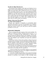
the Nernst equation (Figure 4.9). This half-cell is held under stable
conditions generating a fixed voltage to which the pH-sensing
electrode is compared. There are several types of reference elec-
trode systems. Some such as the standard hydrogen electrode are
important theoretically but not practical for actual use. The most
commonly used reference electrode system is silver/silver chloride
(Ag/AgCl). A silver wire is suspended in a solution of potassium
chloride that has been saturated with silver to replenish the wire
with silver ions. The calomel reference system uses mercury
How to Properly Use and Maintain Laboratory Equipment 77
78 Troutman et al.
instead of silver; manufacturers also provide reference systems
that lack metal ions altogether.
Junction
The junction is the means for the sample and electrode to
contact electrically. The internal filling solution and the sample
mix at the junction. The electrode should have a sufficient flow of
filling solution that passes through the junction so that the sample
and filling solution meet on the sample’s side of the junction. This
better protects the electrode from backflow of sample compo-
nents. An electrical potential (the junction potential) due to the
ion movement develops at the junction contributing a small elec-
Table 4.4 Pipette Troubleshooting Guide
Problem Possible Cause Solution
Pipette drips or Tip is loose or does Use manufacturer recommended
leaks not fit correctly tips
Use more force when putting the
tip on the pipette
Nose cone is scratched Replace the nose cone
Seal of the nose cone Replace the nose cone
leaks
Piston is contaminated Clean and lubricate the piston
by reagent deposits (if recommended)
Replace the seal
Piston is damaged Replace the piston and the
piston seal
Piston seal is damaged Replace the piston seal and
lubricate the piston (if
recommended)
Nose cone has been Retighten nose cone
loosened
Push button does Piston is scraping due Clean and lubricate the piston
not move to contamination
smoothly Seal is swollen due to Open pipette and allow it to
reagent vapors ventilate
Lubricate the piston only if
necessary
Piston is visibly Replace piston seal and piston
damaged or coated
with insoluble
solution
Inaccurate Pipette is leaking Verify that all of the above
volumes situations have been checked
Pipette’s calibration Recalibrate according to
has been changed manufacturer’s specifications
incorrectly
Poor pipetting Refer to section on pipetting
technique technique
How to Properly Use and Maintain Laboratory Equipment 79
trical voltage to the overall measurement system. Generally this
is a minor error. If the flow of filling solution is not adequate, back-
flow can cause this error to increase as ions moving at different
rates cause an accumulation of charges. The filling solution should
be equitransferent (the positive and negative ions can pass freely
through the junction), thus minimizing charge accumulation and
junction potential error. It is difficult to tell if the flow is adequate
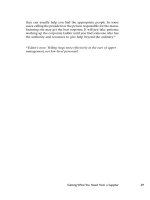
in some electrode junctions. A faster flowing junction such as the
annular, flushable style (Figure 4.10) will reduce the chances of a
poor junction between the sample and electrode. A poor junction
will give erratic readings and thus erratic pH values as the addi-
tional charges are created in the dynamic solution. A change of
6 mV is needed to change the pH by 0.1. It is very difficult to get
reproducibility and accuracy without sufficient flow through a
junction. Sluggish, drifting readings are indications that the flow
may be impaired.
Fill Solution
Reference filling solution or internal filling solution is the elec-
trolyte that is the contact point between the sample and the ref-
erence electrode. The filling solution completes the circuit to
measure the voltage change due to the sample. It is comprised of
salts that conduct electricity and allow the reference electrode to
have a stable voltage for a period of time. The fill solution most
often contains potassium chloride, but incompatibility with some
Figure 4.9 Double-junction
combination electrode. Rep-
roduced with permission from
Thermo Orion Inc.
80 Troutman et al.
samples requires alternate solutions. An example where a differ-
ent filling solution may be required is with ultra-pure, low ionic
strength water. The concentrated KCl would cause the reading to
drift as it mixed with the pure water. A lower ionic strength filling
solution, such as 2.0M KCl saturated with Ag
+
, would produce
faster, more accurate and reproducible readings.
Fill Hole
The filling hole cover on the electrode body must be removed
for a positive flow through the junction.
How Does a pH Meter Function?
Theory
pH is an electrochemical measurement of the activity of the
hydrogen ion, H
+
, in a particular solution. The pH meter measures
voltage, in millivolts (mV), from the “battery” created by the elec-
trodes in an aqueous solution (Figure 4.11). The measured voltage
is the difference between the electrical potentials of the reference
and sensing electrodes. The sensing electrode is usually made of
glass which is very sensitive to changes in hydrogen ion activity.
Software in the pH meter makes the conversion to solution pH
based on previous calibration data stored in its memory.The meter
displays the calculated pH of the solution to the operator. Other
pertinent information, such as temperature, time and date, and
actual millivolts read from the sample are often displayed on more
advanced meters.
Reference Element
Annular Junction
Fill Hole
Sensing Element
Figure 4.10 Annular pH
electrode. Reproduced with
permission from Thermo
Orion Inc.