Microsoft XNA Game Studio Creator’s Guide- P7 pps
Bạn đang xem bản rút gọn của tài liệu. Xem và tải ngay bản đầy đủ của tài liệu tại đây (306.63 KB, 30 trang )
MICROSOFT XNA GAME STUDIO CREATOR’S GUIDE
158
Once the indices have been defined, the SetData() method stores the index ref-
erences in the index buffer. There are several overrides for this method, but for our
needs, all you have to do is pass in the array of indices:
SetData<T>(T[] data);
Managing Vertex Data with Index Buffers and Vertex
Buffers
By themselves, the VertexPositionColor, VertexPositionColorTexture,
VertexPositionTexture, and VertexPositionNormalTexture objects
that you have used will not permit live updates to the position, color, texture, and
normal data. DynamicVertexBuffer objects in combination with index buffers,
on the other hand, will permit updates to large amounts of vertex data. You are going
to want a structure like this when creating an effect such as water.
When initialized, the constructor for the vertex buffer takes parameters for the
current graphics device, vertex type, element count, and buffer usage for memory al-
location:
VertexBuffer( GraphicsDevice graphicsDevice,
Type vertexType,
int elementCount,
BufferUsage usage);
As explained above, BufferUsage options are None as the default, WriteOnly
for efficient writes to memory and for efficient drawing, and Pointsforpoint sprites.
After the vertex data is loaded into an array, the vertex data is moved into the ver-
tex buffer with the VertexBuffer object’s SetData() method. There are several
variations of this method. The method used here only passes the array of vertices:
SetData(VertexBuffer[] vertexBuffer)
Rendering Vertex Buffers with
an Index Buffer Reference
The draw method you use for dynamic vertex buffers—using index buffers—differs
in three ways from the draw methods you have used until now:
1. The SetSource() method is used to set the vertex buffer that stores the
grid, the starting element, and the size of the vertex type in bytes:
graphics.GraphicsDevice.Vertices[0].SetSource(
VertexBuffer vertexBuffer,
int startingElement,
int sizeOfVertex
);
159
2. The GraphicsDevice’s Indices object is set with the corresponding
IndexBuffer object you defined during the program setup:
graphics.GraphicsDevice.Indices = indexBuffer;
3. The DrawIndexedPrimitives() method is used to reference a series of
vertex subsets that are rendered in succession to draw the entire polygon or
surface. DrawIndexedPrimitives() is called for each vertex subset.
graphics.GraphicsDevice.DrawIndexedPrimitives(
PrimitiveType primitiveType,
int startingPointInVertexBuffer,
int minimumVerticesInBuffer,
int totalVerticesInBuffer,
int indexBufferStartingPoint,
int indexBufferEndPoint);
Grid Using Index Buffer Example
This code will implement an index buffer and dynamic vertex buffer to draw a rect-
angle from a set of vertices that is three vertices wide and five vertices long (see Figure
11-3). Drawing a rectangle with a set of vertices that uses index buffers might seem
like a lackluster chore, but don’t be fooled. Index buffers have grit. This little exam-
ple serves as the foundation for creating water waves in Chapter 12, creating terrain
with height detection in Chapter 25, and enabling better lighting across primitive
surfaces in Chapter 22.
This example begins with either the MGHWinBaseCode or MGH360BaseCode
project in the BaseCode folder on this book’s website.
CHAPTER 11
Index Buffers
FIGURE 11-3
Grid rendered from an index buffer
MICROSOFT XNA GAME STUDIO CREATOR’S GUIDE
160
To make this vertex reference system work, an index buffer to reference a grid of
vertices is required. Also, a vertex buffer object is needed to store the vertices. A ver-
tex declaration type is used to set up the buffer when it is being initialized. Add these
object declarations to the top of your game class:
private IndexBuffer indexBuffer; // reference vertices
private VertexBuffer vertexBuffer; // vertex storage
The rows and columns used to draw the rectangle will be referenced with identifi-
ers to help explain how the vertices are arranged. Add these identifiers to the top of
the game class.
const int NUM_COLS = 3;
const int NUM_ROWS = 5;
Indices for referencing the vertex buffer are initialized when the program begins.
The index buffer array is sized to store the total number of vertices contained in one
subset of the vertex buffer. The code that you need to set up the index reference is
contained in the InitializeIndices() method. Add this method to set up your
index reference:
private void InitializeIndices(){
short[] indices; // indices for 1 subset
indices = new short[2 * NUM_COLS]; // sized for 1 subset
indexBuffer = new IndexBuffer(
graphics.GraphicsDevice,// graphics device
typeof(short), // data type is short
indices.Length, // array size in bytes
BufferUsage.WriteOnly); // memory allocation
// store indices for one subset of vertices
// see Figure 11-2 for the first subset of indices
int counter = 0;
for (int col = 0; col < NUM_COLS; col++){
indices[counter++] = (short)col;
indices[counter++] = (short)(col + NUM_COLS);
}
indexBuffer.SetData(indices); // store in index buffer
}
To initialize the short array and index buffer when the program begins, add the
call statement to the Initialize() method:
InitializeIndices();
161
CHAPTER 11
Index Buffers
A VertexBuffer object is initialized to store the vertices used to build the primi-
tive surface. The VertexBuffer object in this example is static and only stores the
vertices that are used to draw the grid or surface. Still, the vertex buffer works in con-
junction with the index buffer as a reference to reduce the total number of vertices
that build the grid or surface. This type of static vertex buffer is especially useful for
drawing lit objects or even terrain where many vertices are needed for detail. When
setting up a vertex buffer, the vertex data is generated and is stored in a temporary ar-
ray. Once all of the vertex values have been assembled, the vertex data is then stored
in the vertex buffer using the SetData() method. To set up your vertices in this effi-
cient buffer, add InitializeVertexBuffer() to your game class:
private void InitializeVertexBuffer(){
vertexBuffer = new VertexBuffer(
graphics.GraphicsDevice, // graphics device
typeof(VertexPositionColorTexture), // vertex type
NUM_COLS * NUM_ROWS, // element count
BufferUsage.WriteOnly); // memory use
// store vertices temporarily while initializing them
VertexPositionColorTexture[] vertex
= new VertexPositionColorTexture[NUM_ROWS*NUM_COLS];
// set grid width and height
float colWidth = (float)2 * BOUNDARY/(NUM_COLS - 1);
float rowHeight = (float)2 * BOUNDARY/(NUM_ROWS - 1);
// set position, color, and texture coordinates
for (int row=0; row < NUM_ROWS; row++){
for (int col=0; col < NUM_COLS; col++){
// set X, Y, Z
float X = -BOUNDARY + col * colWidth;
float Y = 0.0f;
float Z = -BOUNDARY + row * rowHeight;
vertex[col + row * NUM_COLS].Position = new Vector3(X, Y, Z);
// set color
vertex[col + row * NUM_COLS].Color = Color.White;
// set UV coordinates to map texture 1:1
float U = (float)col/(float)(NUM_COLS - 1);
float V = (float)row/(float)(NUM_ROWS - 1);
vertex[col + row * NUM_COLS].TextureCoordinate
= new Vector2(U, V);
}
}
// commit data to vertex buffer
vertexBuffer.SetData(vertex);
}
The vertices must be set when the program begins, so add a call to initialize the
grid vertices in the Initialize() method:
InitializeVertexBuffer();
When a dynamic vertex buffer is being rendered, the SetSource() method reads
data from the vertex buffer that was initialized earlier. The vertex format is passed
into the SetSource() method, so the GraphicsDevice knows how to extract
the data, and the GraphicsDevice’s Indices property is assigned the index
buffer. Finally, DrawIndexedPrimitives() is executed once for each subset of
strips in the grid. Add DrawIndexedGrid() to the games class:
private void DrawIndexedGrid(){
// 1: declare matrices
Matrix world, translation;
// 2: initialize matrices
translation = Matrix.CreateTranslation(0.0f, -0.5f, 0.0f);
// 3: build cumulative world matrix using I.S.R.O.T. sequence
world = translation;
// 4: set shader parameters
textureEffectWVP.SetValue(world*cam.viewMatrix*cam.projectionMatrix);
textureEffectImage.SetValue(grassTexture);
// 5: draw object - select vertex type, vertex source, and indices
graphics.GraphicsDevice.VertexDeclaration = positionColorTexture;
graphics.GraphicsDevice.Vertices[0].SetSource(vertexBuffer, 0,
VertexPositionColorTexture.SizeInBytes);
graphics.GraphicsDevice.Indices = indexBuffer;
// start using Texture.fx
textureEffect.Begin();
textureEffect.Techniques[0].Passes[0].Begin();
MICROSOFT XNA GAME STUDIO CREATOR’S GUIDE
162
163
// draw grid one row at a time
for(intZ=0;Z<NUM_ROWS - 1; Z++){
graphics.GraphicsDevice.DrawIndexedPrimitives(
PrimitiveType.LineStrip, // primitive
Z * NUM_COLS, // start point in buffer for drawing
0, // minimum vertices in vertex buffer
NUM_COLS * NUM_ROWS, // total vertices in buffer
0, // start point in index buffer
2 * (NUM_COLS - 1)); // end point in index buffer
}
// stop using Texture.fx
textureEffect.Techniques[0].Passes[0].End();
textureEffect.End();
}
To draw the grid, call DrawIndexedGrid() from the Draw() method:
DrawIndexedGrid();
Also, to see the grid when it renders, you will need to comment out the instruction
to DrawGround().
When you run the program, the grid appears as shown earlier in Figure 11-3.
However, if the grid is drawn with triangle strips, the output will fill in the area be-
tween the vertices and display a rectangle. This will happen if you change
LineStrip to TriangleStrip in DrawIndexedGrid().
Bystanders might not be impressed that you just created a rectangular surface, but
don’t let that bother you. Let’s put this demo on the backburner for now. We’ll return
to it in later chapters to let it rip.
C
HAPTER 11 REVIEW EXERCISES
To get the most from this chapter, try out these chapter review exercises.
1. Try the step-by-step example in this chapter, but this time change the
number of rows to 125 and the number of columns to 55. View the
project using line strips and triangle strips.
2. Compared to methods that are used in previous chapters for storing vertices
without an index reference, how many vertices are saved when using an
index buffer to draw a grid that is 60 rows high and 35 rows wide?
CHAPTER 11
Index Buffers
3. The example presented in this chapter shows how to use a static
VertexBuffer object with index buffers. What is the advantage
of doing this? What type of vertex buffer permits updates to vertices
at run time?
4. List three ways that the DrawIndexedPrimitives() method is different
from the DrawUserPrimitives() method.
MICROSOFT XNA GAME STUDIO CREATOR’S GUIDE
164
CHAPTER
CHAPTER 12
Combining
Combining
Images for
Images for
Better Visual
Better Visual
Effects
Effects
166
THIS
chapter demonstrates various ways of combining images to gen-
erate compelling visual effects; more specifically, sprites and
multitexturing will be discussed. By the end of the chapter, you will be able to use im-
age files that store more than one image frame to create cool heads-up display (HUD)
animations in your 2D or 3D games. You will also be able to blend two textures to-
gether to generate intricate detail for effects such as terrain or a water simulation. Al-
though games are not defined solely by their aesthetics, no one has ever complained
that a game’s graphics looked too good. Your players will appreciate any effort you
put into maximizing your visual effects.
S
PRITES
As discussed in Chapter 4, a sprite is an animated 2D image. You can animate sprites
by moving them in the window. Also, if your sprite has more than one frame, you can
swap frames to animate them.
Image Frame Swapping for 2D Animations
Image frame swapping creates an animation similar to old-style page-flipping anima-
tions used to create simple cartoons. The sprite is animated at run time by adjusting
the texture’s UV coordinates at fixed time intervals. Sprites store multiple image
frames because adjusting UV coordinates at run time—to switch image frames—is
faster than switching to a different image file.
For 3D games, a 2D sprite offers a very simple way to customize and animate the
heads-up display, or a game dashboard. This type of sprite could be used to create an
animated radar scope on the console of a flight simulation game.
SpriteBatch
For the 2D effect, a sprite object is created with the SpriteBatch class:
SpriteBatch spriteBatch = new SpriteBatch(GraphicsDevice);
A SpriteBatch object is actually already included in the XNA template project
code that is generated using the New Project dialog box. For our purposes this is the
only one you will need.
Primitive objects are not needed to display the image when using SpriteBatch
methods. As a result, setting up the sprite is easier than setting up textured primitive
surfaces; the SpriteBatch object draws the image on its own. For the 2D object, all
drawing is done between the SpriteBatch object’s Begin() and End() methods.
167
The syntax for the Draw() method is designed for drawing on a 2D window. The
first parameter references the Texture2D object that stores the image file; the sec-
ond parameter references the position, height, and width of a rectangle in the 2D
window; and the third parameter references the starting pixel’s X and Y position in
the image and the height and width—in pixels—to be drawn. The fourth parameter
sets the color of the sprite in case you want to shade it differently from the colors al-
ready in the image.
Be aware that there are several other overrides for SpriteBatch.Draw(); how-
ever, this is the one that we’ll be using for our examples:
SpriteBatch.Draw(
// Texture2D object
Texture2D texture,
// window
new Rectangle(
int topLeftXWindowCoord,
int tpLeftYWindowCoord,
int displayWidthInPixels,
int displayHeightInPixels),
// image source
new Rectangle(
int startingXPixel,
int startingYPixel,
int pixelWidthDrawn,
int pixelHeightDrawn),
// color
Color Color.ColorType);
The rendering for a SpriteBatch object is still triggered from the Draw()
method.
Restoring 3D Drawing Settings After Drawing
with a SpriteBatch
If your 3D game uses 2D sprites, you need to be aware of how this will impact your
drawing routines. The 2D SpriteBatch automatically resets the
GraphicsDevice’s render states to draw 2D graphics in the window. While this is
helpful, if the settings are not restored to enable 3D rendering, you may not see your
3D graphics—and if you do, they may not display properly. Ideally, when rendering
your SpriteBatch objects, you should draw them last in the Draw() method so
that they layer on top of the 3D graphics.
CHAPTER 12
Combining Images for Better Visual Effects
Your graphics device states should be reset to turn off transparency and to re-en-
able 3D graphics after drawing with the SpriteBatch. You must also reset the cull-
ing option back to the default used by your game. Culling designates the face of an
object that is not drawn, so it should be the face that is not visible to the user. Culling
options include CullClockwiseFace, CullCounterClockwiseFace, and
None. The base code uses CullMode.None to prevent your surfaces from disap-
pearing just in case you mistakenly arrange your vertices in the same order as your
culling option. However, for performance gains, you definitely will want to cull
nonvisible sides of your surfaces when you are rendering large groups of vertices, so
be aware that you have this option.
The following code for resetting the state belongs in the Draw() method right af-
ter you draw with SpriteBatch:
graphics.GraphicsDevice.RenderState.CullMode = CullMode.None; // no cull
graphics.RenderState.DepthBufferEnable = true; // enable 3D on Z
graphics.RenderState.AlphaBlendEnable = false; // end transparent
graphics.RenderState.AlphaTestEnable = false; // per pixel test
// enable tiling
graphics.SamplerStates[0].AddressU = TextureAddressMode.Wrap;
graphics.SamplerStates[0].AddressV = TextureAddressMode.Wrap;
Instead of manually resetting the render states, you can add
SaveStateMode.SaveState as a parameter for the SpriteBatch object’s Be-
gin() instruction when drawing it. This will restore the render states back to their
original settings before the sprite is drawn. It’s important to note that this saves and
restores all the render states, so it’s more costly than restoring the render states by
hand:
spriteBatch.Begin(SpriteBlendMode.AlphaBlend,
SpriteSortMode.Immediate,SaveStateMode.SaveState);
Rendering Sprites Within the Title Safe Region
of the Window
When running games on the Xbox 360, some televisions will only show 80 percent of
the game window. The PC shows 100 percent of the window, so some adjustments
may be needed to account for this platform difference. Here is a routine that returns
the bottom-left pixel in the window for drawing a SpriteBatch object so that it is
positioned properly in the visible region of the window regardless of where the pro-
ject runs:
MICROSOFT XNA GAME STUDIO CREATOR’S GUIDE
168
169
Rectangle TitleSafeRegion(Texture2D texture, int numFrames){
int windowWidth = Window.ClientBounds.Width;
int windowHeight = Window.ClientBounds.Height;
// some televisions only show 80% of the window
const float UNSAFEAREA = 0.2f;
const float MARGIN = UNSAFEAREA / 2.0f;
// return bounding margins
int top, left, height, width;
left = (int)(windowWidth * MARGIN);
top = (int)(windowHeight * MARGIN);
width = (int)((1.0f - UNSAFEAREA) * windowWidth - texture.Width);
height = (int)((1.0f - UNSAFEAREA) * windowHeight
- texture.Height/numFrames);
return new Rectangle(left, top, width, height);}
I
MAGE FRAME ANIMATIONS
The SpriteBatch class is limited to drawing images that are flat. To perform image
frame swapping inside the 3D world, you must use textured primitives without the
SpriteBatch class to animate your textures. Animating textures through image
frame swapping is useful for effects such as flashing signs and blinking lights inside
your world. When a sprite is drawn in a 3D environment, the image frames are
swapped at regular intervals by adjusting the UV coordinates.
Sprite on the Heads-Up-Display Example
This example animates a two-frame sprite. In this example, the SpriteBatch class
is used to swap frames within the image so that it appears in the 2D game window as
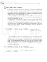
a blinking light. Figure 12-1 shows the sprite image on the right and the warning light
animation on the left. The two images on the left will be swapped at each interval. To
the gamer, the light appears to blink on and off every 0.5 seconds.
This example begins with either the MGHWinBaseCode project or the
MGH360BaseCode project found in the BaseCode folder on this book’s website. A
Texture2D object is used to load and reference the image. To try this example, first
add this declaration to the top of the game class:
private Texture2D spriteTexture;
CHAPTER 12
Combining Images for Better Visual Effects
A timer is used to trigger the frame change for the sprite, which creates the blink-
ing light animation. To implement the timer, class-level declarations are required
to store the frame number (frameNum), the time spent in the current timer inter-
val (intervalTime), and the time lapse since the last interval
(previousIntervalTime):
int frameNum = 1;
private double intervalTime = 0; // time in current interval
private double previousIntervalTime = 0; // interval time at last frame
Next, the Timer() method is added to the methods section to check for the com-
pletion of each 0.5-second interval. The Timer() method calculates the remainder
of the amount of time since the interval started, divided by 500 milliseconds. When
the remainder has increased compared to the remainder calculated for the previous
frame, the interval is incomplete. When the remainder has decreased since the previ-
ous frame, a new interval has been entered, and the Timer() method returns a posi-
tive result. The positive result triggers a frame swap for the sprite. Checking the
remainders in this manner prevents the variable from growing beyond the variable’s
storage capacity, because it is reset every interval. Even though the remainder is usu-
ally positive when a new interval is detected, the overshot from the interval start is
miniscule, and tracking the remainder makes this algorithm self-correcting. In this
manner, the Timer() implements animations that appear to be synchronized with
real time:
MICROSOFT XNA GAME STUDIO CREATOR’S GUIDE
170
FIGURE 12-1
An animated sprite in the game window
171
bool Timer(GameTime gameTime){
bool resetInterval = false;
// add time lapse between frames and keep value between 0 & 500 ms
intervalTime += (double)gameTime.ElapsedGameTime.Milliseconds;
intervalTime = intervalTime % 500;
// intervalTime has been reset so a new interval has started
if (intervalTime < previousIntervalTime)
resetInterval = true;
previousIntervalTime = intervalTime;
return resetInterval;
}
The warninglight.png file is also loaded by code into the Texture2D object in the
LoadContent() method. The warninglight.png file can be obtained from the Im-
ages folder on this book’s website. The image needs to be added to the Images folder
in your project so it can be loaded by the content pipeline. To reference this in your
project, right-click the Images folder in the Solution Explorer, choose Add, and then
select Existing Item. A dialog will appear that allows you to navigate to the image and
select it. Once the warninglight.png file is selected, it will appear in your project
within the Solution Explorer, and you can then load it with the following instruction:
spriteTexture = Content.Load<Texture2D>("Images\\warninglight");
To ensure that the sprite is positioned properly in the game window, add the
routine that was discussed earlier to retrieve the starting pixel for drawing in the
window:
Rectangle TitleSafeRegion(Texture2D texture, int numFrames){
int windowWidth = Window.ClientBounds.Width;
int windowHeight = Window.ClientBounds.Height;
// some televisions only show 80% of the window
const float UNSAFEAREA = 0.2f;
const float MARGIN = UNSAFEAREA / 2.0f;
// return bounding margins
int top, left, height, width;
left = (int)(windowWidth * MARGIN);
top = (int)(windowHeight * MARGIN);
CHAPTER 12
Combining Images for Better Visual Effects
width = (int)((1.0f - UNSAFEAREA) * windowWidth - texture.Width);
height = (int)((1.0f - UNSAFEAREA) * windowHeight
- texture.Height/numFrames);
return new Rectangle(left, top, width, height);
}
The next method to add is DrawAnimatedHud(). DrawAnimatedHud()
checks the timer to see if the set interval has completed. If the timer returns a true
value—indicating that it just ticked into a new interval—the frame in the image is in-
cremented or reset. The SpriteBatch object calls the Begin() method to start the
drawing. Begin() allows the developer to set the SpriteBlendMode option to
specify the type of blending. This could include:
AlphaBlend For removing masked pixels
Additive For summing source and destination colors
None For standard rendering
If you want to remove the transparent pixels, you can use
SpriteBlendMode.AlphaBlend as a parameter in the SpriteBatch’s Begin()
method. The picture in the warninglight.png file was created with a transparent back-
ground, so the pixels will not appear when the image is drawn with alpha blending.
The SpriteBatch’s Draw() method applies four parameters. The first parame-
ter is the gameTime object, which is applied to ensure that the animation runs at a
consistent speed. The second parameter is the X and Y position for the starting pixel
where the sprite is to be drawn. A Texture2D object is passed as a third parameter
to allow you to set the width and height of the area to be drawn. The fourth parame-
ter is the total number of frames, which allows you to split up the image so it is drawn
one section at a time. To draw the sprite so it is positioned properly in the window,
add DrawAnimatedHud() to your project:
void DrawAnimatedHUD(GameTime gameTime, Vector2 startPixel,
Texture2D texture, int numFrames){
// get width and height of the section of the image to be drawn
int width = texture.Width; // measured in pixels
int height = texture.Height / numFrames; // measured in pixels
if (Timer(gameTime)){
frameNum += 1; // swap image frame
frameNum = frameNum%numFrames; // set to 0 after last frame
}
spriteBatch.Begin(SpriteBlendMode.AlphaBlend);
spriteBatch.Draw(
MICROSOFT XNA GAME STUDIO CREATOR’S GUIDE
172
173
// texture drawn
texture,
// area of window used for drawing
new Rectangle((int)startPixel.X, // starting X window position
(int)startPixel.Y, // starting Y window position
width, height), // area of window used
// area of image that is drawn
new Rectangle(0, // starting X pixel in texture
frameNum*height, // starting Y pixel in texture
width, height), // area of image used
// color
Color.White);
spriteBatch.End();
}
DrawAnimatedHud() needs to be called in the Draw() method, but only after
instructions for the drawing of 3D objects are called. This allows the 2D sprite to
overlay the 3D graphics:
const int NUM_FRAMES = 2;
Rectangle safeArea = TitleSafeRegion(spriteTexture, NUM_FRAMES);
Vector2 startPixel = new Vector2(safeArea.Left, safeArea.Bottom);
DrawAnimatedHUD(gameTime, startPixel, spriteTexture, NUM_FRAMES);
As mentioned earlier, the SpriteBatch object automatically adjusts the render
state of the GraphicsDevice object to draw in 2D but does not change it back. To
draw in 3D, the original settings must be reset in the Draw() method after the
SpriteBatch object is drawn:
// A: Culling off B: Enable 3D C: transparency off D: pixel testing
graphics.GraphicsDevice.RenderState.CullMode = CullMode.None;//A
graphics.GraphicsDevice.RenderState.DepthBufferEnable = true; //B
graphics.GraphicsDevice.RenderState.AlphaBlendEnable = false; //C
graphics.GraphicsDevice.RenderState.AlphaTestEnable = false; //D
// re-enable tiling
graphics.GraphicsDevice.SamplerStates[0].AddressU
= TextureAddressMode.Wrap;
graphics.GraphicsDevice.SamplerStates[0].AddressV
= TextureAddressMode.Wrap;
When you run the program, the light will appear as shown back in Figure 12-1.
CHAPTER 12
Combining Images for Better Visual Effects
Animated Texture Example
The previous example is useful for implementing 2D sprites in the game window.
This example shows how to create a similar effect for textures used inside your 3D
world. When the example is complete, a flashing “danger” sign will appear in your
game. Maybe you don’t need a flashing danger sign, but you need a flashing billboard
on your speedway, or maybe you want to display scrolling text on one of the objects
in your 3D world. An animated texture can do this. You could even use a similar ef-
fect to create a cartoon in your game.
To get these effects off the window and inside your game world, you will need to
use textured primitive objects. The frames in the image are swapped by modifying the
UV coordinates at the start of each interval. The fraction of the image displayed in
each frame is based on the total frames stored in the image. The image used for this
example has just two frames. Figure 12-2 shows the two frames of the image on the
left and the animation on the right at different intervals.
This example begins with either the MGHWinBaseCode project or the
MGH360BaseCode project in the BaseCode folder on this book’s website. Also, the
dangersign.png file must be downloaded from this book’s website and referenced in
your project from the Solution Explorer.
An array of four vertices will be used to render a triangle strip with a danger-sign
texture. This vertex object declaration is needed at the top of the game class so the
vertices can be stored, updated, and used for drawing while the game runs:
private VertexPositionColorTexture[] vertices
= new VertexPositionColorTexture[4];
MICROSOFT XNA GAME STUDIO CREATOR’S GUIDE
174
FIGURE 12-2
Two frames of an image (left) and animation (right)
175
CHAPTER 12
Combining Images for Better Visual Effects
The position, texture, and color data are set when the program begins. Add
InitializeAnimatedSurface() to the game class to set up these vertices for
the rectangle used to display the danger sign:
private void InitializeAnimatedSurface(){
Vector2 uv = new Vector2(0.0f, 0.0f);
Vector3 pos = new Vector3(-0.5f, 1.0f, 0.0f);
Color col = Color.White;
vertices[0]=new VertexPositionColorTexture(pos,col,uv);// top left
pos.X=-0.5f; pos.Y=0.0f; pos.Z=0.0f; uv.X=0.0f; uv.Y=1.0f;
vertices[1]=new VertexPositionColorTexture(pos,col,uv);// lower left
pos.X= 0.5f; pos.Y=1.0f; pos.Z=0.0f; uv.X=1.0f; uv.Y=0.0f;
vertices[2]=new VertexPositionColorTexture(pos,col,uv);// top right
pos.X= 0.5f; pos.Y=0.0f; pos.Z=0.0f; uv.X=1.0f; uv.Y=1.0f;
vertices[3]=new VertexPositionColorTexture(pos,col,uv);// lower right
}
The four vertices that are used to draw the rectangle with the danger-sign texture
must be initialized when the program launches. To do this, inside Initialize(),
add the following call to InitializeAnimatedSurface():
InitializeAnimatedSurface();
Also, a Texture2D object is required to store the texture, so a declaration for
signTexture needs to be in the module declarations area of the game class:
private Texture2D signTexture;
The dangersign.png file (shown in Figure 12-2) must be read into memory when
the program begins. To do this, add a statement to load the image in the
LoadContent() method:
signTexture = Content.Load<Texture2D>("Images\\dangersign");
The texture’s frame must alternate every 500 milliseconds, so a timer is used to
track when these intervals are completed. To assist with setting up the timer and
swapping texture frames, module-level declarations are used to store the current
frame number as well as the times of the current and previous frame:
private double intervalTime = 0;
private double previousIntervalTime = 0;
MICROSOFT XNA GAME STUDIO CREATOR’S GUIDE
176
The timer code used for this example follows the same algorithm used in the previ-
ous example. This time, it will set the interval used to display each section of the im-
age. Add Timer() to enable frame swapping every 500 milliseconds:
bool Timer(GameTime gameTime){
bool resetInterval = false;
// add time lapse between frames and keep value between 0 & 500 ms
intervalTime += (double)gameTime.ElapsedGameTime.Milliseconds;
intervalTime = intervalTime % 500;
// intervalTime has been reset so a new interval has started
if (intervalTime < previousIntervalTime)
resetInterval = true;
previousIntervalTime = intervalTime;
return resetInterval;
}
When animating textures, you must update the UV coordinates to switch frames.
The current frame is tracked with the variable
frameNum
, which is declared at the
top of the game class:
int frameNum = 0;
Since the texture frames are arranged vertically in this example, when the timer
signals the completion of an interval, the V coordinate for each vertex is adjusted to
switch frames. UpdateTextureUV() requires three parameters to implement this
routine. A GameTime argument controls the speed of the animation. A Texture2D
parameter provides height and width properties for the image file that is referenced.
Lastly, the number of frames is passed so the image can be properly sectioned into
separate frames. Adding UpdateTextureUV() to your game class provides the
routine needed to swap the frames of your image at regular intervals. This swapping
creates the animation effect:
void UpdateTextureUV(GameTime gameTime,Texture2D texture,int numFrames){
int width = texture.Width; // image width in pixels
int height = texture.Height; // image height in pixels
int frameHeight = height/numFrames; // height of image section drawn
if (Timer(gameTime)){
frameNum += 1; // swap image frame
frameNum = frameNum % numFrames; // set to zero after last frame
}
177
CHAPTER 12
Combining Images for Better Visual Effects
float U, V; // update UV coordinats
// top left
U = 0.0f; V = (float)frameNum * frameHeight/height;
vertices[0].TextureCoordinate = new Vector2(U,V);
// bottom left
U = 0.0f; V = (float)((frameNum + 1.0f) * frameHeight)/height;
vertices[1].TextureCoordinate = new Vector2(U, V);
// top right
U = 1.0f; V = (float)frameNum * frameHeight/height;
vertices[2].TextureCoordinate = new Vector2(U,V);
// bottom right
U = 1.0f; V = (float)((frameNum + 1.0f) * frameHeight)/height;
vertices[3].TextureCoordinate = new Vector2(U,V);
}
UpdateTextureUV() is called from the Update() method to map a different
portion of the image to the surface each interval:
const int NUM_FRAMES = 2;
UpdateTextureUV(gameTime, signTexture, NUM_FRAMES);
The DrawAnimatedTexture() routine is identical to the routines used for
drawing any textured object that you have used until now. Check the comments in
this code for details:
private void DrawAnimatedTexture(){
// 1: declare matrices
Matrix world, translation;
// 2: initialize matrices
translation = Matrix.CreateTranslation(0.0f, 0.0f, -BOUNDARY / 2.0f);
// 3: build cumulative world matrix using I.S.R.O.T. sequence
world = translation;
// 4: set shader parameters
textureEffectWVP.SetValue(world*cam.viewMatrix*cam.projectionMatrix);
textureEffectImage.SetValue(signTexture);
// 5: draw object - primitive type, vertices, #primitives
TextureShader(PrimitiveType.TriangleStrip, vertices, 2);
}
Inside the Draw() method, just before the End() method is called for the tex-
ture shader, the animated texture needs to be drawn. When transparency is involved,
the transparent objects must be rendered last. In other words, they are drawn after the
opaque 3D objects. To enable transparency, several RenderStates for
the GraphicsDevice must be adjusted. Alpha blending must be enabled by set-
ting AlphaBlendEnable = true. The opaque pixels are drawn by setting
SourceBlend = Blend.SourceAlpha, and the masked portion of the image is
filtered out by setting DestinationBlend = Blend.InverseSourceAlpha.
Alpha blending is disabled when the drawing is complete.
Add the following code to set up transparency for your textured surface and to
render it as the last item in your list of 3D objects that are drawn:
graphics.GraphicsDevice.RenderState.AlphaBlendEnable = true;
graphics.GraphicsDevice.RenderState.SourceBlend = Blend.SourceAlpha;
graphics.GraphicsDevice.RenderState.DestinationBlend
= Blend.InverseSourceAlpha;
DrawAnimatedTexture();
graphics.GraphicsDevice.RenderState.AlphaBlendEnable = false;
When you run the program, it will show a flashing danger sign in the 3D world, as
shown earlier in Figure 12-2. Unlike the sprite example, this sign can be viewed from
different angles as a player travels through the world.
M
ULTITEXTURING
Multitexturing is a technique that blends two or more images into one texture.
Multitexturing offers interesting possibilities for creating graphics effects, such as
adding detail texturing to terrain, simulating currents of water, and changing the ap-
pearance of existing textures at run time.
Multitexturing uses multipass rendering to blend more than one textured surface
each frame. Each render of the object is triggered during one pass in the shader.
(There are several references to shaders in this example, so you may find a review of
Chapter 6 to be helpful.) The developer can set each pass to specify how the objects
are filtered, textured, and drawn.
Multipass Rendering from the Shader’s Technique
A shader that implements multitexturing is almost identical to the shader used for ap-
plying textures in Chapter 9. The only difference with a multipass shader is that the
technique implements more than one pass. In each pass, different blending and filter-
MICROSOFT XNA GAME STUDIO CREATOR’S GUIDE
178178
179
ing can be triggered and different functions within the shader can be executed. This
technique demonstrates typical syntax for a multitexturing shader:
technique MultiTexture{
pass p0 // first pass
{ // declare and initialize vs and ps
Vertexshader = compile vs_1_1 VertexShader();
pixelshader = compile ps_1_1 PixelShader();
}
pass p1 // second pass
{ // declare and initialize vs and ps
Vertexshader = compile vs_1_1 VertexShader();
Pixelshader = compile ps_1_1 PixelShader();
}
}
Calling a Pass in the Shader
Each pass is called between the effect’s Begin() and End() methods. The code syn-
tax presented here is similar to code that would be used to select and execute two
passes within the shader. Note that in each pass a separate textured surface is ren-
dered:
effect.Begin(); // start shader
effect.Techniques[0].Passes[0].Begin(); // *START 1ST PASS
drawObject(SURFACE0); // draw 1st surface
effect.Techniques[0].Passes[0].End(); // *END 1ST PASS
effect.Techniques[0].Passes[1].Begin(); // *START 2ND PASS
drawObject(SURFACE1); // draw 2nd surface
effect.Techniques[0].Passes[1].End(); // *END 2ND PASS
effect.End(); // end shader
Water Using Multitexturing Example
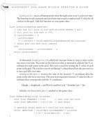
In this example, a multitexturing technique simulates a flowing river. To create the
water, this example uses two images of rocks that resemble what you might find near
a riverbed (see Figure 12-3). The first image (on the left) serves as the blurred river
bottom. The second image (on the right) is used for the water surface. The second im-
age is a picture of similar stones that uses a lighter shade for easier blending. In every
CHAPTER 12
Combining Images for Better Visual Effects
frame, the second image’s texture coordinates are adjusted so that it appears to slide
over the first texture.
The image on the right is actually created from three identical images. The middle
image is inverted to ensure a seamless wraparound when the maximum V texture co-
ordinate is reached and reset back to the start. Only one-third of the second texture is
shown at a time. In each frame, the visible portion of the texture is shifted by a scaled
increment, based on the time lapse between frames.
The images are combined using a shiny blend to give the illusion of light bouncing
off the water.
This example shows how to create a clear dynamic water effect by blending the
two images. This code begins with the solution from the “Grid Using Index Buffer
Example” section in Chapter 11.
MICROSOFT XNA GAME STUDIO CREATOR’S GUIDE
180
FIGURE 12-3
Stationary texture (left) and moving texture (right)
181
One of the first items that must be modified is the shader. Replace the technique in
the Texture.fx file with this version to enable multipass rendering. This revision calls
the same vertex shader and pixel shader twice. Before each pass is called, the applica-
tion sets the texture so that a different textured surface is rendered during each pass:
technique multiTexture{
pass p0 // first pass
{ // declare and initialize vs and ps
vertexshader= compile vs_1_1 VertexShader();
pixelshader = compile ps_1_1 PixelShader();
}
pass p1 // second pass
{ // declare and initialize vs and ps
vertexshader= compile vs_1_1 VertexShader();
pixelshader = compile ps_1_1 PixelShader();
}
}
At the class level within the game class, constants are declared to identify each sur-
face in the multitexture:
const int SURFACE0 = 0; const int SURFACE1 = 1; const int NUM_LAYERS = 2;
To generate the effect of more naturally rounded waves, more vertices are re-
quired. At the top of the game class, replace the existing definitions for the total num-
ber of columns and rows, in the vertex grid, with these revised declarations:
private const int NUM_COLS = 30;
private const int NUM_ROWS = 30;
Two Texture2D objects are required to store each layer used to create the run-
ning water. During each pass in the shader, only one of the textures is applied—de-
pending on whether the riverbed or moving watery surface is being rendered. To
make both textures available throughout the game class, a Texture2D array is de-
clared at the top of the class:
private Texture2D[] waterTexture = new Texture2D[NUM_LAYERS];
The two images of rocks—water0.bmp and water1.bmp—will need to be in the
Images folder under the Content node in your game project so they can be loaded
with Load() in the LoadContent() method. You can download the image files
from this book’s website. They can be found in the Images folder. Place this code in
CHAPTER 12
Combining Images for Better Visual Effects
the LoadContent() method so that the images will be loaded when the program
begins:
waterTexture[SURFACE0] = Content.Load<Texture2D>("Images\\water0");
waterTexture[SURFACE1] = Content.Load<Texture2D>("Images\\water1");
The UV coordinates for each surface in the multitextured water will be used differ-
ently. The riverbed will remain stationary but the UV coordinates for the running
water will be updated dynamically. Later, in the example, the Y coordinates for all
vertices in each surface will be adjusted every frame to create a wave pattern. Since
the position is going to be updated, a DynamicVertexBuffer object is needed to
store each set of vertices. Replacing the existing class-level VertexBuffer declara-
tion from the Chapter 11 “Index Buffer” example with this
DynamicVertexBuffer array declaration will permit efficient dynamic updates
to large numbers of vertices every frame:
// offscreen storage and updates
VertexPositionColorTexture[] surface0
= new VertexPositionColorTexture[NUM_ROWS * NUM_COLS];
VertexPositionColorTexture[] surface1
= new VertexPositionColorTexture[NUM_ROWS * NUM_COLS];
// buffer for drawing
DynamicVertexBuffer[] vertexBuffer = new DynamicVertexBuffer[2];
A different set of vertices is used for each surface in this multitexture effect so they
can be updated independently of each other. This structure is different than the previ-
ous index buffer from Chapter 11, which does not permit dynamic updates to the
vertices at run time. To set up the dynamic vertex structure, replace the existing
InitializeVertexBuffer() method with this one:
private void InitializeVertexBuffer(){
for(int i=0; i<NUM_LAYERS; i++) // vertex buffer for drawing
vertexBuffer[i] = new DynamicVertexBuffer(
graphics.GraphicsDevice,
NUM_COLS*NUM_ROWS*VertexPositionColorTexture.SizeInBytes,
BufferUsage.WriteOnly | BufferUsage.Points);
// set grid width and height
float colWidth = (float)2*BOUNDARY/(NUM_COLS - 1);
float rowHeight = (float)2*BOUNDARY/(NUM_ROWS - 1);
MICROSOFT XNA GAME STUDIO CREATOR’S GUIDE
182