Brushless Permanent Magnet Motor Design- P7 docx
Bạn đang xem bản rút gọn của tài liệu. Xem và tải ngay bản đầy đủ của tài liệu tại đây (2.32 MB, 15 trang )
Motor Drive Schemes177
discharge. Later, when the current decays to I~ a switch closes and
the inductance charges until the next clock pulse appears. Once again
the switching frequency is fixed by the clock frequency.
Important aspects
of
this PWM scheme include:
• Current control is not as precise here, since there is no
fixed
tolerance
band that bounds the current.
• The frequency at which switches change state is a fixed design pa-
rameter.
• Acoustic and electromagnetic noise are relatively easy to filter be-
cause the switching frequency is fixed.
• This PWM method has ripple instability that produces subharmonic
ripple components for duty cycles below 50 percent (Kassakian,
Schlecht, and Verghese, 1991; Anunciada and Silva, 1991). While
this instability does not lead to any destructive operating mode, it
is a chaotic behavior that reduces performance. The predominant
current ripple occurs at one-half the switching frequency.
Dual current-mode PWM
This PWM method was developed by Anunciada and Silva (1991) to
eliminate the ripple instability present in the previous two methods.
Their scheme combines the clocked turn-ON and clocked turn-OFF
methods in a clever way. For duty cycles below 50 percent, the method
implements stable clocked turn-ON PWM, whereas for duty cycles
178 Chapter Seven
above 50 percent, the method implements stable clocked turn-OFF
PWM.
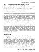
As illustrated in Fig. 7.18, this method has two clock signals, where
the turn-OFF clock is delayed one-half period with respect to the turn-
ON clock. Operation is determined by logic that initiates inductor
charging when the turn-ON clock pulse appears or the current reaches
I~, and initiates inductor discharge when the turn-OFF clock appears
or the current reaches /
+
. As shown in the figure, the method smoothly
moves from one mode to the other. This scheme has all the attributes
of
the two previous PWM schemes, except for the ripple instability.
Furthermore, this scheme reduces to hysteresis PWM
if
the clock fre-
quency is low compared with the rate at which the inductance charges
and discharges.
Triangle PWM
Triangle PWM is a popular voltage PWM scheme that is commonly
used to produce a sinusoidal PWM voltage. When used in this way, it
is called sinusoidal PWM (Kassakian, Schlecht, and Verghese, 1991).
Motor Drive Schemes
179
Processed
Application of this scheme to current control is accomplished by letting
the PWM input be a function of the difference between the desired
current and the actual current. As shown in Fig. 7.19, both the turn-
ON and turn-OFF
of
the switch are determined by the intersections
of
the triangle waveform and the processed current error. As the pro-
cessed current error increases, so does the switch duty cycle. Typically,
the processed current error is equal to a linear combination of the
current error and the integral
of
the current error, i.e., PI control is
used. As a result, as the steady-state error goes to zero, the switch duty
cycle will go to the correct value to maintain it there. Though Fig. 7.19
shows a unipolar triangle waveform and error signal, both signals can
also be bipolar, in which case zero current error produces a 50 percent
duty cycle PWM signal (Murphy and Turnbull, 1988).
Summary
The PWM methods discussed above represent the most common meth-
ods implemented in practice. Each method has its own strengths and
weaknesses; no one PWM scheme is the best choice for every motor
drive. Implementation details for the above PWM methods were not
presented so that attention would
focus
on fundamental switching con-
cepts. For reference, conceptual logic diagrams for each method are
shown in Fig. 7.20. These diagrams apply for positive currents only.
When the reference current is bipolar, more complex logic diagrams
are required.
Motor Drive Schemes
switching
frequency,
the smaller the current error will be. On the other
hand, the higher the switching frequency, the greater the switching
loss incurred by the switches. Furthermore, PWM schemes are only as
accurate as the current sensors used. Sensor type, placement, shielding,
and signal processing are all critical to accurate operation
of
a current
control PWM method.
Appendix
A
List of Symbols
A Area (m
2
)
B Magnetic
flux
density (T)
B
a
Armature reaction
flux
den-
sity (T)
B
g
Air gap
flux
density (T)
B
r
Magnet remanence (T)
C
A
Flux concentration factor
D Diameter (m)
E Voltage,
emf (V)
E
b
Back
emf (V)
E
max
Maximum back
emf (V)
F Magnetomotive force,
mmf (A)
Force (N)
H Magnetic field intensity
(A/m)
H
c
Magnet coercivity (A/m)
I Current (A)
I
s
Total slot current (A)
J
s
Slot current density (A/m
2
)
J
max
Maximum current density
(A/m
2
)
L Length (m)
Inductance (H)
L
e
End turn inductance (H)
L
g
Air gap inductance (H)
L
s
Slot leakage inductance (H)
M Mutual inductance (H)
N Number
of
turns
N
m
Number
of
magnet poles
N
p
Number
of pole
pairs
N
ph
Number
of
phases
N
s
Number
of
slots
N
Number
of
slots per magnet
pole
N
sp
Number
of
slots per phase
N
*
spp
Number
of
slots per pole per
phase
p
Permeance (H)
Average power (W)
Pc
Permeance
coefficient
Pel
Core loss (W)
Pe
Eddy current power loss (W)
P
g
Air gap permeance (H)
P
h
Hysteresis power loss (W)
Php
Power (hp)
Pr
Resistive, ohmic, or I
2
R loss
(W)
R Resistance (fl)
Reluctance (H
_1
)
Radius (m)
S
Motor speed (rpm)
183
184 Appendix A
T Torque (N-m)
Temperature (°C)
V
Volume (m
3
)
W Energy (J)
w
c
Coenergy (J)
d Depth or distance (m)
d
s
Slot depth (m)
e
Voltage (V)
e
b
Back
emf (V)
f
Frequency (Hz)
fe
Electrical frequency (Hz)
fm
Mechanical frequency (Hz)
frs
Force density (N/m
2
)
g
Air gap length (m)
ge
Effective
air gap length (m)
i
Current (A)
k
Constant
K
Carter
coefficient
k
C
p
Conductor packing factor
kd
Distribution factor
k
m
l
Magnet leakage factor
K
Pitch factor
K
Skew factor
Kt
Stacking factor
i Length (m)
lm
Magnet length (m)
n
c
Number
of
turns per coil
n
s
Number
of
turns per slot
n
tpp
Number
of
turns per pole per
phase
P
Instantaneous power (W)
Q
Heat density
(
W/m
2
)
r
Radius (m)
V Velocity (m/s)
Wbi
Back iron width (m)
w
s
Slot width (m)
Wsb
Slot bottom width (m)
Wt
Tooth width (m)
Wtb
Tooth bottom width (m)
r Core loss density (W/kg)
a
cp
Coil-pole
fraction,
T
C
/T
P
«m
Magnet
fraction,
T
W
/T
P
OT
S
Slot
fraction,
W
S
/T
S
a
sd
Shoe depth fraction,
(di
+ d
2
)/w
tb
8
Skin depth (m)
P
Permeability (H/m)
PR
Magnet recoil permeability
Pa
Relative amplitude permea-
bility
Pd
Relative differential permea-
bility
Pr
Relative permeability
Po
Permeability
of free
space,
4TR
• 10
7
H/m
<f>
Magnetic
flux
(Wb)
V
Efficiency (%)
A Flux linkage (Wb)
e
Angular position (rad or deg)
e
c
Angular coil pitch (rad or
deg)
e
e
Angular electrical position
(rad or deg)
dm
Angular mechanical position
(rad or deg)
dp
Angular pole pitch (rad or
deg)
0
S
Angular slot pitch (rad or
deg)
P
Electrical resistivity (fl«m)
Pbi
Back iron mass density
(kg/m
3
)
cr
Electrical conductivity
[(il-m)-
1
]
?c
Coil pitch (m)
r
m
Magnet width (m)
T
P
Magnetic pole pitch (m)
T
S
Slot pitch (m)
0)
Frequency (rad/s)
(O
E
Electrical frequency (rad/s)
OJm
Mechanical frequency (rad/s)
Appendix
B
Common Units
and Equivalents
Property SI unit Equivalents
Magnetic flux 1 weber (Wb) 10
8
maxwells or lines
10
5
kilolines
Flux density 1 tesla (T) 1 Wb/m
2
10
4
gauss
64.52 kiloline/in
2
Magnetomotive 1 ampere (A)
1.257 gilberts
force (mmf)
Magnetic field 1 ampere/meter (A/m) 2.54-10"
2
ampere/in
intensity 1.257-10"
2
oersted
Permeability of 47t-10~
7
henry/meter (H/m) 1 henry = 1 Wb/A
free space
Resistivity 1 ohm-meter (fl-m) 10
2
il-cm
39.37 ii-in
Back emf 1 volt-second/radian 104.7 V/k rpm
constant
Velocity 1 radian/second (rad/s) 30/irrpm = 9.549 rpm
l/(27r) rpm = 0.1592 hertz
Length 1 meter (m) 39.37 in
100 cm
1 cm = 0.3937 in
1 mm = 39.37 mils
Area 1 meter
2
(m
2
) 1550 in
2
10
4
cm
2
10.764 ft
2
1.974-10
9
circular mil
Volume 1 meter
3
(m
3
) 6.1024-10
4
in
3
10
6
cm
3
35.315 ft
3
Mass 1 kilogram (kg) 1000 grams
2.205 lb
35.27 oz
6.852-10
"
2
slug
185
186 Appendix B
Property SI unit Equivalents
Mass density 1 kilogram/meter
3
(kg/m
3
)
6.243-10
-2
lb/ft
3
3.613-10"
5
lb/in
3
5.780 10-
4
oz/in
3
Force 1 newton (N)
1 m-kg/s
2
0.2248 pound (lb
f
)
3.597 ounces (oz
f
)
10
5
dynes
Torque 1 newton-meter (N-m)
141.61 oz-in
8.85 lb-in
0.738 lb-ft
10
7
dyne cm
1.02 10
4
g em
Energy
1
joule (J) 1 W-s
9.478-10'
4
Btu
Power 1 watt (W) 1 J/s
1/746 hp = 1.3405 10"
3
hp
Current density 1 ampere/meter
2
(A/m
2
)
10-" A/cm
2
6.452-10"
4
A/in
2
5.066-10"
10
A/circular mil
Energy density
1
joule/meter
3
(J/m
3
)
1.6387-10-
6
J/in
3
1.5532 10
-8
Btu/in
3
1.257 10
2
gauss-oersted (G-Oe)
1 MG-Oe = 7.958 kJ/m
3
Power density 1 watt/kilogram (W/kg) 0.4535 W/lb
(mass) 6.083-10"
4
hp/lb
Power density 1 watt/meter
2
(W/m
2
)
10 "
4
W/cm
2
(area) 6.452-10"
4
W/in
2
Force density 1 newton/meter
2
(N/m
2
) 1.450-10'
4
lb/in
2
(psi)
Bibliography
Anunciada, V., and M. M. Silva (1991), "A New Current Mode Control Process and
Applications,"
IEEE Transactions
on
Power Electronics,
vol. 6, no. 4, pp. 601-610.
Brod, D. M., and D.
W.
Novotny (1985), "Current Control
of VSI-PWM
Inverters,"
IEEE
Transactions
on
Industry Applications,
vol. IA-21, No. 4, pp. 562-570.,
Chai, H. D. (1973), "Permeance Model and Reluctance Force between Toothed Struc-
tures,"
Proceedings
of
the Second
Annual Symposium
on
Incremental Motion Control
Systems and
Devices,
B. C. Kuo, ed., Urbana, IL, pp. K1-K12.
de Jong, H. C. J. (1989), AC
Motor
Design: Rotating
Magnetic Fields
in a Changing
Environment,
Hemisphere Publishing Company, New York.
This
text can be viewed
as a
successful
attempt to rewrite the
material
presented
in
the classic
motor design
texts
of
the
first half of this
century. As
opposed
to those earlier texts, the notation
and
terminology
in this text
reflects modern
thinking.
Freimanis, M. (1992), "Hybrid Microstepping Chopper Can Reduce Iron Losses,"
Motion
Control.
April 1992, pp. 36-39.
Gogue, G. P., and J. J. Stupak (1991), "Professional Advancement Courses, Part A:
Electromagnetics Design Principles
for
Motors/Actuators, Part
B:
DC
Motor/Actuator
Design,"
PCIM Conference
1991, Sept. 22-27, Universal City, CA.
This
set
of notes
is used by the authors in day
long
short courses. The basics
of
magnetic circuit
modeling
are
covered.
A very
good discussion
of permanent magnets
and magnetizing
techniques
and
fixtures
is
presented.
Some equations are presented. but
for
the most
part
the
notes contain
a
wealth
of
practical information
not
found in college
textbooks.
Hague, B. (1962),
The Principles
of
Electromagnetism
Applied to
Electrical Machines,
Dover Publications, New York. This text is a reprint
of a
text
originally
published
in
1929. It offers
an amazing
collection
of
analytically derived field distributions
and
force
equations applicable to
electrical
machines.
Hanselman, D. C. (1993), "AC Resistance of Motor Windings Due to Eddy Currents,"
Proceedings
of
the
Twenty-Second Annual
Symposium
on Incremental Motion Control
Systems and
Devices,
B. C. Kuo, ed., Urbana, IL, pp. 141-147.
Hendershot, J. R. (1991), Design of
Brushless Permanent Magnet Motors,
Magna Physics
Corp., Hillboro, OH.
This
text
is
more
of a survey of
motor design, material
properties,
and
manufacturing
techniques than a text
on motor design itself. Very few
equations
are presented, but the immense amount of practical
information
presented is
indis-
pensable. An
excellent companion
to the text you're
holding.
Holtz, J. (1992), "Pulsewidth Modulation—A Survey,"
IEEE Transactions on Industrial
Electronics.
vol. 39, no. 5, pp. 410-420.
Huang, H W. M. Anderson, and E. F. Fuchs (1990), "High-Power Density and High
Efficiency Motors for Electric Vehicle Applications,"
Proceedings of the International
Conference
on
Electric Machines,
Cambridge, MA, pp. 309-314.
Kassakian, J. G„ M. F. Schlecht, and G. C. Verghese (1991),
Principles
of
Power Elec-
tronics,
Addison Wesley, Reading, MA.
This
text is
refreshingly different from
most
power
electronics
texts in that it seeks to convey fundamental principles rather than
just extensively analyze every
possible
power
electronic
circuit.
What
the text lacks
is
sufficient
extensive examples
which
put the
fundamental principles
to work.
Leonhard, W. (1985).
Control
of
Electrical Drives,
Springer-Verlag, New York. A classic
text on the
control of all common
motor types.
Li. Touzhu, and G. Slemon (1988), "Reduction
of
Cogging Torque in Permanent Magnet
Motors,"
IEEE Transactions
on
Magnetics,
vol. 24, no. 6, pp. 2901-2903.
187
188 Bibliography
Liwschitz-Garik, M., and C. C. Whipple (1961).
Alternating-Current Machines,
Second
Edition, D. Van Nostrand Company, Princeton NJ.
This
text,
first printed
in
1946,
is
one
of the
last classic texts on electric machines.
It's
one
of those
books that many
well-seasoned motor designers
have
on
their
bookshelf. The notation and terminology
used in this text is antiquated but
discernible
with some
effort.
McCaig, M., and A. G. Clegg (1987),
Permanent Magnets
in
Theory and Practice,
Second
Edition, John Wiley & Sons, New York. This text represents one
of
the very
few
readable texts on permanent magnets. As the title states, the text presents both
theory and practice,
and does
a good job of it.
This
text is a rewrite of a prior
edition
and does contain significant information on neodymium-iron-boron
magnet material.
This
is an excellent text
for
those who seek a greater
understanding
of permanent
magnets than that
typically
presented in a motor book.
McPherson, G., and R. D. Laramore (1990), An
Introduction to Electrical Machines
and
Transformers,
Second Edition, John Wiley & Sons, New York.
This
is one example
of the many
college
texts available in this area.
This
text is both more
readable
and
more
thorough
than most.
Miller,
T.
J. E.
(1989), Brushless Permanent-Magnet
and
Reluctance
Motor
Drives,
Oxford
University Press, New York.
This
text is a survey of modern brushless motors. It is
very
readable
but lacks some depth in most areas simply because the text covers so
much ground. Overall, it is a required text
for
those involved in the business of
brushless motors.
Mukheiji,
K.
C., andS. Neville (1971), "Magnetic Permeance ofldentical Double Slotting:
Deductions from Analysis by F. W. Carter,"
Proceedings of the IEE,
vol. 118, no. 9,
pp. 1257-1268.
Murphy, J. M. D., and F. G. Turnbull (1988), Power
Electronic Control of AC Motors,
Pergamon Press, Oxford, UK. This text covers the electronic control
of all
major
motor types. Just about every
control
scheme is
illustrated.
Some power semicon-
ductor
material is
presented.
It is by
far
the most comprehensive text
of its
kind.
Nasar, S. A. (1987),
Handbook
of
Electric Machines,
McGraw-Hill, New York.
This
text
is
truly
a
handbook. It contains
chapters
submitted
by numerous
authors, and
a
wide
variety
of motor
types are
considered.
A
thorough
presentation
of magnetic
circuit
analysis and its
limitations
is made in
Chapter
2.
Prina, S. R. (1990),
The
Analysis and Design
of Brushless
DC
Motors,
Ph.D. Thesis,
University of New Hampshire, Durham, NH. This thesis correlates the measured
characteristics
of
a brushless permanent-magnet motor with results predicted by
finite
element analysis.
This
thesis is extremely important to those wishing to know
the
limitations of finite
element analysis.
Qishan, G., and G. Hongzhan (1985), "Effect of Slotting in PM Electric Machines,"
Electric Machines and Power
Systems, vol. 10, pp. 273-284.
Roters, H. C. (1941),
Electromagnetic Devices,
John Wiley & Sons, New York.
This
is a
classic
text on
magnetic
modeling. The circular-arc, straight-line approach to
perme-
ance
modeling
is
introduced in
this text.
Sebastian, T., G. R. Slemon, and M. A. Rahman (1986), "Design Considerations for
Variable Speed Permanent Magnet Motors,"
Proceedings
of
the International Confer-
ence
on
Electrical Machines,
Miinchen, Germany, pp. 1099-1102.
Sebastian, T., and G. R. Slemon (1987), "Operating Limits of Inverter Driven Permanent
Magnet Motor Drives,"
IEEE Transactions
on
Industry Applications,
vol. IA-23, no.
2, pp. 327-333.
Slemon, G. R., and X. Liu (1990), "Core Losses in Permanent Magnet Motors,"
IEEE
Transactions
on
Magnetics,
vol. 26, no. 5, pp. 1653-1655.
Slemon, G. R. (1991), "Chapter
3:
Design
of
Permanent Magnet AC Motors
for
Variable
Speed
Drives," Performance
and
Design
of
Permanent Magnet AC Motor Drives,
IEEE
Press, New York.
This reference
is
from
the published notes of a
day-long
short
course
presented by six
well-respected
authors at the
IEEE Industry Applications
Society
Conference
in Dearborn,
MI.
Ward, P. A., and P. J. Lawrenson (1977), "Magnetic Permeance
of
Doubly-Salient Air-
gaps,"
Proceedings of the Institution
of
Electrical Engineers,
vol. 124, no. 6, pp. 542-
544.
Index
Air gap:
inductance, 80, 81
modeling, 19-21
Armature reaction, 89-91
Axial flux topology, 122, 123
Back emf, 46, 59, 70-72, 113-115
in axial flux design, 147, 148
in radial flux design, 131
sinusoidal, 121
trapezoidal, 121
Back iron, 64
BLi law, 57, 59, 91
BLv law, 47, 59
Carter coefficient, 22, 68
Clocked turn-OFF PWM, 176, 177
Clocked turn-ON PWM, 175, 176
Coenergy, 48, 50, 51
for computing inductance, 81
in doubly-excited systems, 50, 51
in singly-excited systems, 48-50
in the presence
of
a PM, 51
Coercivity (H
c
), 31
(See also Remanence)
Cogging torque, 7, 58, 112, 113, 117-120
Coil, 75
magnetic circuit model, 18, 19
Coil-pole fraction, 115, 144, 145
Commutation, 155
Conductor packing factor, 87, 133
Core loss, 28-30, 96
Current:
in a A-connected motor, 172
in axial flux design, 148
in an H-bridge switch, 164
in radial flux design, 132
in a sine wave motor, 173
in a Y-connected motor, 168, 169
A connection, 170-173
Detent:
positions, 7
torque, 7, 58, 112, 113, 117-120
Distribution factor, 115
Dual air gap construction, 99-101
Dual current-mode PWM, 177, 178
Eddy current:
in conductors, 88, 89
loss, 28, 29
End turn leakage inductance, 82-84
Energy, 48, 49, 51
in doubly-excited systems, 50, 51
in singly-excited systems, 48-50
in the presence
of
a PM, 51
(See
also Work)
Factor:
conductor packing, 87, 133
distribution, 115
flux concentration, 37, 38, 143
magnet leakage, 67, 142
pitch, 115-117
skew, 119
stacking, 30
Faraday's law, 46
Finite element analysis, 13, 14
Flux concentration, 37, 38
Flux concentration factor, 37, 38, 143
Flux linkage, 41, 42, 69, 70
Flux squeezing, 24
Force, 52, 73, 74
conductor, 91-93
cogging, 93-95
relationship to torque, 4
relationship to power, 52
due to skewing, 120
(See
also
Torque)
Fraction:
coil-pole, 115, 144, 145
magnet, 66, 141
slot, 24, 120, 129
Fractional pitch, 111
Frequency, fundamental electric, 11
Fringing, 19
Fundamental design issues, 96-99
189
190 Index
H-bridge, 161-163
shoot-through fault in, 165
Hysteresis:
loop, 26, 28
loss, 28, 29
PWM, 174, 175
I
2
R loss, 76
Inductance:
air gap, 80, 81
in axial flux design, 149, 150
end turn leakage, 82-84
mutual, 42, 85, 86
in radial flux design, 134, 135
self, 41, 42, 78-84
slot leakage, 81, 82, 109
Lamination, 29, 30
Law:
BLi, 57, 59, 91
BLv, 47, 59
Faraday's, 46
Lenz's, 46
Loading, electric and magnetic, 99
Lorentz force equation, 56, 63
Loss:
core, 28-30, 96
eddy current, 28, 29
hysteresis, 28, 29
ohmic, resistive, or I
2
R, 76
Magnet (See Permanent magnet)
Magnet aspect ratio, 67, 68
Magnetic circuit concepts, 14
Magnet fraction, 66, 141
Magnet leakage factor, 67, 142
Magnet leakage flux, 66
Magnet shaping, 120
Magnetomotive force (mmf), definition
of, 16
Motor action, 5
Motor size, 11, 12
Mutual inductance, 42, 85, 86
Ohmic loss, 76
Peak current density, 133
Permanent magnet (PM):
bonded versus sintered, 30
magnetic circuit model, 34-36
permeance, 35
properties:
coercivity, 31
Permanent magnet (PM), properties
(Cont.):
maximum energy product, 33
recoil permeability, 32
remanence, 31
temperature dependence of, 32-34
types, 30
Permeance, definition of, 16, 17
Permeance coefficient (PC), 32, 38, 68, 143
Permeability:
of
freespace, 26
recoil, 32
relative, 26
relative amplitude, 27
relative differential, 27
Pitch:
factor, 115-117
pole, 66, 67, 70, 115-117
slot, 22-24, 108, 129
Pole:
consequent, 103
magnet, 8
salient, 9, 107
Position, mechanical and electrical, 10
Power: v.
electrical, 59
mechanical, 52, 53, 59
Pulse width modulation (PWM) methods:
clocked turn-ON, 175, 176
clocked turn-OFF, 176, 177
dual current-mode, 177, 178
hysteresis, 174, 175
triangle, 178, 179
Radial flux topology, 122
Recoil permeability, 32
Relative permeability, 26
Reluctance, definition of, 17
Remanence, B
r
, 31
(See also Coercivity)
Resistance:
in axial flux design, 148, 149
end turn, 86
in radial flux design, 133, 134
slot, 86
winding:
ac, 88, 89
dc, 87, 88
Resistive loss, 76
Resistivity
of
annealed copper, 87
Right-hand rule, 56
Right-hand screw rule, 18
Ripple instability, 176, 177
Index 191
Rotor, 1, 3
Rotor variations, 103-105
Self inductance, 41, 42, 78-84
Shoes, 107, 118
Six step drive, 167
Skew factor, 119
Skewing, 118-120
Skin depth, 88
Slot:
definition, 9
fraction, 24, 120, 129
leakage inductance, 81, 82, 109
modeling, 21-24
Speed voltage (See Back emf)
Stacking factor, 30
Stator, 1, 3
Stator variations, 106, 107
Teeth, 9, 107
Three-phase motors:
A connection, 170-173
Y connection, 166-170
Topologies:
axial flux, 3, 121-123
radial flux, 3, 121, 122
Torque: 4, 5, 53
in axial flux design, 147
cogging or detent, 7, 58, 112, 113, 117-
120
from a macroscopic viewpoint, 54-56
from a microscopic viewpoint, 56, 57
with respect to motor size, 11
mutual or alignment, 7, 55, 58
in radial flux design, 131
relationship to force, 4
relationship to power, 52
reluctance, 7, 55, 57, 58
repulsion, 7
Triangle PWM, 178, 179
Triplen or triple-n, 170, 171, 173
Turn, 75
Winding:
chorded, short-pitch, or fractional-
pitch, 115, 118
double-layer lap, 77
single-layer lap, 76, 77
single-layer wave, 77, 78
solenoidal, 9
Work, 52
(See
also Energy)
Y connection, 166-170
ABOUT THE AUTHOR
Duane C. Hanselman is an Associate Professor in Electri-
cal Engineering at the University
of
Maine, Orono. He
holds a Ph.D. and an M.S. in Electrical Engineering from
the University
of
Illinois and is a Senior member
of
the In-
stitute
of
Electrical and Electronics Engineers (IEEE). Dr.
Hanselman is the author
of
numerous articles on motors
and motion control. He is a coauthor
of MATLAB® Tools
for Control
System Analysis and Design and a contributing
author
of Teaching
Design in
Electrical Engineering.
Everything you
need
to
know
to design tomorrow's
most popular motor today!
Brushless permanent-magnet motors are increasingly the motor
of choice in a wide range of applications, from hard disk drives,
laser printers, and VCRs to a variety of industrial and military uses
such as robotics, factory automation, and electric vehicles. As
their cost continues to decline, they're sure to become a dominant
motor type because of their simplicity, reliability, and efficiency.
With this book you can find out how these motors work, what their
fundamental limitations are, and how to design them.
In an easy-to-follow, keep-it-simple style, the book's author
Duane C. Hanselman begins with the fundamental concepts of
generic motor operation and design. Based on these fundamental
concepts he identifies and explains terminology, i.e., the buzz-
words, common to motor design. In addition, he describes how the
fundamental concepts both influence and limit motor design and
performance. Hanselman also discusses brushless DC and
synchronous motor design for both cylindrical (radial) and pan-
cake (axial) topologies.
All the concepts and analytical tools you need are here in one
source. A wealth of figures, tables, and equations are provided to
illustrate and document all the essential aspects of motor design.
Whether you design motors or specify and design systems that
use them, you'll find this up-to-date reference absolutely essential.
Cover Design: Kay Wanous
ISBN D-OT-GEbDEi-?
9 78007Ö260252
McGraw-Hill, Inc.
Serving the Need for Knowledge
1221 Avenue of the Americas
New York, NY 10020