The Black Art of Xbox Mods- P5 potx
Bạn đang xem bản rút gọn của tài liệu. Xem và tải ngay bản đầy đủ của tài liệu tại đây (1.26 MB, 30 trang )
106
CHAPTER
6
Installing
a Soldered Mod Chip
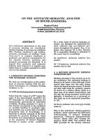
FIGURE
6.10
The pin header
is
soldered to the
LPC.
FIGURE
6.11
The
LPC
is
located near the Nvidia
MCPX
processor.
Installing
a Pin
Header
(All Revisions) 107
Removing
Pin 4
You
first need to remove pin 4 from the pin header.
On
earlier Xbox revisions,
point
4
on
the LPC
is
blocked,
so
it's obvious,
but
on
1.6,
point
4
is
open.
You
absolutely must
not
use
pin
4 because
your
mod
chip
and/or
Xbox can become damaged.
Pin 4
is
shown in Figure 6.12. Note that pins
on
the LPC start at the top right (pin 1), down to
pin
2,
up and left to pin
3,
and
down again to pin 4 (see Figure 6.13).
FIGURE
6.12
The
LPC
has 16
points;
only
the
first
12 are used.
Pin 4
is
shown in the jaws
of
my needle-nose pliers in Figure 6.13.
Take the pin in your pliers, as shown in Figures 6.14
and
6.15, and pull it straight out. Figure 6.16
shows the final result. Make sure you remove the correct pin; otherwise, you might
end
up need-
ing a new pin header!
Inserting
the
Pin
Header
Next, take the pin header and insert it into the LPC holes.
Be
very careful
of
the orientation! Point
1 on the LPC
is
nearest the back
of
the Xbox, while
point
16
is
nearest the front
of
the Xbox. The
pin header
is
placed into the first
12
LPC holes. Because the pin header
must
be soldered from
the
bottom
side
of
the Xbox, you can use tape to hold in the pin header while you work
on
the
other side (see Figure 6.17). While the figure shows clear tape (for illustrative purposes), 1
strongly recommend you use electrical "black" tape instead.
If
you can manage it, it
is
even advis-
able to use no tape at all,
as
it
is
possible to pull up motherboard traces when you remove the tape.
108
CHAPTER
6
Installing
a Soldered Mod Chip
FIGURE
6.13
Locating pin 4 on
the
pin header (for removal).
FIGURE
6.14
Grasping pin 4
with
needle-nose pliers.
Installing
a Pin
Header
(All
Revisions)
109
FIGURE
6.15
Removing pin 4
(note
that
the pin header
is
upside
down).
FIGURE
6.16
Make sure
you
remove the
correct
pin.
110
CHAPTER
6 Installing a Soldered Mod
Chip
FIGURE
6.17
Use
tape
to
hold
the
pin header in place
while
you
solder
it
in on the
bottom
of
the
motherboard.
Soldering
the
Pins
Turn over the motherboard and locate the
LPC
underneath (shown in Figure 6.18).
FIGURE
6.18
The
LPC
on
the
opposite
side
of
the
motherboard.
Installing
a Pin
Header
(All
Revisions)
111
Heat up your soldering iron
and
wait for it to warm up completely.
Be
very careful with the tip
of
the soldering iron! If this
is
your first experiment with soldering, I strongly recommend that
you practice with a broken circuit board first before you make an
attempt
on
a working Xbox
motherboard; otherwise, you may
end
up with a "practice board" right there and will need a new
Xbox motherboard entirely!
You
might use old worthless
ISA
or
PCI cards,
or
even cheap elec-
tronic toys
to
gain some experience with your soldering iron.
If
you do not yet own a soldering iron, I recommend you get a holder and soldering tools along
with the iron. These tools are inexpensive; I purchased the tools shown in Figure 6.19 from Fry's
Electronics for about $25.
You
can find similar tools at Radio Shack,
Ace
Hardware, and other
stores. Even Wal-Mart carries soldering tools. Don't get suckered into buying a $40 soldering
"gun." Just choose a small iron that
is
easy to handle; imagine how it will feel in your hand while
working up close with your cherished Xbox motherboard.
You
want something small, light, easy
to use.
FIGURE
6.19
Buy
inexpensive
soldering
tools.
The soldering iron itself can be any cheap iron
as
long
as
it has a removable tip. The iron holder
has a tip cleaning sponge that, when wet, provides an excellent way to clean your soldering iron
tip. Just wipe the tip clean
on
the wet sponge after every joint to keep the tip clean and
hot!
If you
use the iron for anything other
than
soldering (such
as
melting wire insulation or drawing pic-
tures
on
a piece
of
wood!), the tip will become damaged, with "cold spots" that render it unus-
able. Tips are inexpensive. Just buy a new tip any time you need one instead
of
trying to work with
a bad tool.
Apply
solder
to
heated
joints,
not
directly
with
the
soldering
iron. The iron
is
not
a
paintbrush!
Remember, a
joint
is
the
intersection
of
the
two
points
you
are
trying
to
solder
together,
which
will
be a
motherboard
lead and a loose
wire
end
in this case.
112
CHAPTER
6
Installing
a Soldered Mod Chip
I am convinced that there
is
no absolutely right way to solder unless you are a trained electronics
engineer. A
few
simple tips are
all
you need to successfully solder in a pin header (or the 1.6 LPC
rebuild wires later in this chapter). A lot
of
experienced modders will tell you to use rosin flux
sparingly when you solder. Well, I use a lot! I love this stuff.
If
you've ever tried to solder anything
without rosin flux, I'm sure you have experienced the trauma
of
having your solder
not
cooper-
ate!
Rosin flux will help you to get the solder exactly where you want it. Basically, rosin flux
attracts solder. When you have two small wires that are coated with flux, and it
is
heated, the sol-
der will naturally flow between the touching wires without coaxing. Figure 6.20 shows a bottle
of
flux purchased from Radio Shack.
FIGURE
6.20
Rosin
flux
is
a necessity when soldering!
Rosin
flux
is
like
grease for electron-
ics work and
is
non-conductive.
Although I don't want you to make a
mess, you don't have to worry about
flux messing up your Xbox. Use the
provided brush
to
dab a little bit
of
fllLx
on whatever wires
or
points you
need
to
solder;
then
apply heat with
your iron to each point
to
melt the flux a little and make it work. Hold the iron to the parts for a
few
seconds (and no more!); then touch solder
to
the joint.
At
this point, soldering becomes
as
much an art
as
a science because you don't want to damage the electronics,
but
you do need to
Installing
the
DO
Wire
113
heat up the leads enoLlgh to melt the solder. Some experienced solderers will argue
that
flux
is
needed only when using non-rosin solder. So what? I find it
is
easier to solder when using flux, so
I
LIse
it.
YOLI
should do what works best for you,
not
what others tell you to do, because
most
peo-
ple are just searching for personal affirmation
(that
is,
"followers").
After you have finished soldering the pins sticking through the LPC holes
on
the
bottom
of
the
motherboard, the result should look something like Figure
6.21.
FIGURE
6.21
The pin header
has
been soldered to the motherboard.
Installing
the
DO
Wire
Ifyou have
an
Xbox 1.0
through
1.4, all you need to do next
is
install the
DO
wire and you're done.
Ifyou own a
1.6, skip ahead to the section titled "Xbox Revision 1.6."
The
DO
wire
is
located in two different locations
on
Xbox revision
LOlLI
and
1.2-1.4.
If
you own
an Xbox
1.0
or
1.1, refer to Figure 6.22 for the location
of
the
DO.
If
you own an Xbox 1.2, 1.3,
or
1.4, refer to Figure 6.23 for the
DO
location.
You
will need to solder the blue lead
of
the
DO
wire that came with your Xenium chip (with the
little adapter that plugs into the
DO
port
on the Xenium).
If
yOll
don't
have one, that's
not
a prob-
lem: Just solder a wire from the
DO
point
to the solder pad
on
the Xenium labeled
"DO"
(it's above
the "X" in the Xenium logo).
114
CHAPTER
6
Installing
a Soldered Mod Chip
FIGURE
6.22
The
DO
location
on
Xbox
1.0 and
1.1
motherboards.
FIGURE
6.23
The
DO
location
on Xbox
1.2-1.4
motherboards.
If
you do have a Xenium
DO
wire adapter, you will also need to solder the black lead to a ground,
which can be the nearest motherboard screw pad on either the top
or
bottom
of
the
Xbox Revision
1.6
Mod
Chip
Installation
115
motherboard.
If
you solder to the
bottom,
you can
run
the negative wire through one
of
the open
LPC holes (13-16).
Xbox Revision
1.6
Mod
Chip
Ins
tallation
Xbox revision 1.6 motherboards have a different layout for the LPC than previous revisions,
and
the
DO
is
no more, replaced with a new point called LFRAME. Figure 6.24 shows
the
LPC
on
a
1.6
motherboard. Although it looks the same, the LPC
no
longer has a 5-volt pin. In addition, the
3.3-volt pin and four
of
the "LAD" data lines were removed altogether.
FIGURE
6.24
The
LPC
on
a revision 1.6 motherboard.
Double-Checking
the
Revision
Before you start, are you absolutely sure you have a 1.6 Xbox? Aside from going through
all
the
version-checking techniques discussed in Chapter
3,
"Identifying Your Xbox Revision," you can
easily spot a 1.6
motherboard
because it comes equipped with an Xcalibur video chip (shown in
Figure 6.25).
116
CHAPTER
6
Installing
a Soldered Mod Chip
FIGURE
6.25
The Xcalibur video chip
is
found
only
on Xbox revision 1.6.
Installing
the
Pin
Header
The pin header
is
installed in exactly the same manner on
1.6
as
it
is
for previous revisions, so
refer to "Installing a Pin Header
(All
Revisions)" earlier in this chapter
if
you skipped over that
section and follow the directions to install your pin header. When you're done, it's time to rebuild
the
LPC.
Rebuilding
the
lPC
Why does the LPC need to be rebuilt? The
1.6
motherboard
is
significantly different from all pre-
vious revisions, and
that
includes the LPC. The mod chips are designed
to
work with any revi-
sion,
so
it
wouldn't make sense
to
custom-build a "1.6-only" mod chip. Instead,
we
solder in the
pin header
as
usual and then solder connection wires to make the
1.6
LPC resemble the LPC
on
an earlier Xbox revision. Ready to start?
Figure 6.26 shows the points that you can refer to when soldering the
five
wires onto the moth-
erboard (remember that the points are inverted because you are nowlooking at the bottom
of
the
motherboard). Also, note the orientation
of
the motherboard
in
this chapter, where pin 1
is
on
the right side
in
these figures, and make sure
yOll
orient your motherboard in the same manner.
Refer to Table
6.1
for wiring connections.
Xbox
Revision
1.6
Mod
Chip
Installation
117
FIGURE
6.26
Rebuilding the
LPC
on a 1.6 requires five wires.
TABLE
6.1
LPC
Rebuild
Wiring
Connections
for
Xbox
1.6
Wire
LPC
PIN To
Point
Pin
6 Open
point
near
R7P4
Pin
7 Open
point
near C7R2
Pin
2
Pin
8
2
3
4
5
Pin
10
Pin
9
Open
point
above
Pin
10
Open
point
near R7T3
Wire 1
The first wire
is
soldered between
pin
q
and
the
point
labeled R7P4, as
shown
in Figures 6.27
and
6.28.
Wire
2
The
second wire
is
soldered
between
pin
7
and
the
point
near
label C7R2, as
shown
in Figures
6.29
and
6.30.
118
CHAPTER
6 Installing a Soldered Mod
Chip
FIGURE
6.27
The
first
connection:
pin 6 to R7P4.
FIGURE
6.28
The
first
wire
has been soldered in place.
Xbox
Revision
1.6
Mod
Chip
Installation
1
19
FIGURE
6.29
The second
connection:
pin 7
to
open
point
near C7R2.
FIGURE
6.30
The
second
wire
has been soldered in place.
120
CHAPTER
6
Installing
a Soldered Mod
Chip
Wire
3
The third wire
is
soldered between pins 2 and 8 on the LPC,
as
shown in Figures 6.31 and 6.32.
FIGURE
6.31
The
third
connection: pin 2
to
pin 8.
FIGURE
6.32
The
third
wire has been soldered
in
place.
Xbox
Revision
1.6
Mod
Chip
Installation
121
Wire
4
The
fourth
wire
is
soldered
between
pin
10
and
the
open
point
directly above
pin
10, as
shown
in
Figures 6.33
and
6.34.
Note
that
"up"
is
a relative
term
that
refers specifically
to
the
figure.
FIGURE
6.33
The fourth connection: pin 10 to open point directly above pin 10.
FIGURE
6.34
The fourth wire has been soldered
in
place.
122
CHAPTER
6
Installing
a Soldered Mod Chip
Wire
5
The fifth wire
is
soldered between pin 9 and the open point that
is
best described
as
being near
R7T3.
It
is
actually just to the right (relative to the figure)
of
R7T2
and
R7T3 (see Figures 6.35
and 6.36).
FIGURE
6.35
The
fifth
connection: pin 9 to open
point
near R7T3.
FIGURE
6.36
The
fifth
wire
has
been soldered in place.
Xbox
Revision
1.6
Mod
Chip
Installation
123
Installing
the
LFRAME
Wire
Xbox revision 1.6 has
no
DO
point. Instead, it simply uses a different point called LFRAME that
seems to fulfill the same purpose
as
the
DO.
While the
DO
is
a type
of
ground that causes the Xbox
to
boot
from the LPC (instead
of
the built-in BIOS), the LFRAME
is
a standard signal
of
the Intel
bus protocol. The LFRAME
point
on
the 1.6
is
located close to the Xyclops chip at a
point
called
U7Cl (see Figure 6.37).
FIGURE
6.37
The
LFRAME
point
is
located near U7Cl .
Figure 6.38 shows a closer view
of
the LFRAME point. It
is
just below the "U" in the
U7Cl
label
on the motherboard near the bottom-right corner
of
the Xyclops chip.
After you have soldered the blue wire to the
U7Cl
point, solder the black wire to a ground point,
such
as
the one shown in Figure 6.39. Note that you do
not
absolutely need to use the
DO
adapter
provided with the Xenium (because it does require the ground); you can solder a single wire from
the
LFRAME
point to the
DO
solder pad on the Xenium
and
then
not
need the ground wire,
but
the small DO/LFRAME plug
is
helpful when you need to completely remove the Xenium. (Your
mod chip
of
choice
will
have similar solder points
but
may
not
be exactly the same
as
the
Xenium.)
124
CHAPTER
6
Installing
a Soldered Mod
Chip
FIGURE
6.38
The
LFRAME
point
is
located near U7Cl .
FIGURE
6.39
The
DO
adapter
has
been soldered
to
the
LFRAME
and
ground,
ready
to
be
plugged
into
the
Xenium.
Troubleshooting
125
Troubleshooting
Even
the most skilled solderer may have problems getting an Xbox to
boot
after a
mod
chip has
been installed because all it takes
is
one
LPC lead or a faulty
DO
connection to render the Xbox
unbootable. The following sections provide some pointers that may help to
at
least narrow down
the possible problems you might have.
Problem
with
the
DO/LFRAME
The most
common
problem
is
a
DO
connection (or LFRAME
on
the 1.6),in which case the
mod
chip will appear to be powered,
but
the Xbox will just
boot
up normally.
What
happens in this
case
is
that the DO/LFRAME causes the Xbox to boot off the LPC, and when it's
not
jumpered,
the Xbox ignores the LPC
(and
the
mod
chip
is
powered up,
but
useless).
If
your Xbox boots up with the Microsoft Dash after installing your
mod
chip, check
the
DO/LFRAME,
as
you have at least soldered the 3.3v power line to the pin header correctly,
but
may
still have other pins incorrectly soldered. The problem with no response
is
with the DO/LFRAME
point. Double-check the position on the motherboard where you soldered it; make sure no lines
are crossed.
If
you used the Xenium
DO
wire, make sure you soldered the blue wire to the
DO/LFRAME, and the black wire to
ground-this
can be any nearby
motherboard
screw-down
point.
Problem
with
the
LPC
Whether or not your
mod
chip LED lights up, if the Xbox "FRAGS"
(a
condition in which the
front power light blinks red and green), the problem
is
one
or more faulty pin header wires sol-
dered to the LPC.
On
earlier Xboxes, you likely have pin header leads that are
not
soldered prop-
erly,
and
1.6
owners may have incorrect "LPC rebulld" solder points that are faulty. Double-check
all
of
your solder points, making sure that they are solid, with clean, bright solder making a good
connection.
If
your solder
is
gray in color
or
not
smooth looking, the connections might be expe-
riencing resistance, which the fine tolerances
of
the Xbox electronics might sense as a fault.
Other
Problems
If
you believe your soldering work
is
good
but
the
mod
chip still doesn't work (no LED at all),
your only recourse
is
to remove the pin header and start over from scratch because it
is
very pos-
sible that you have crossed lines underneath the pin header itself.
To
remove the solder, I recom-
mend
using desolder braid, which works great: Just touch the
braid
to a solder point, heat it
up
with your iron, and the solder will be drawn to the braid. Under
no
circumstances should you
ever touch a
point
with the iron and then try to pull the pin header loose!
That
is
guaranteed to
pull up traces off tile motherboard, which
is
pretty much a DOA situation.
126
CHAPTER
6 Installing a Soldered Mod
Chip
If
all
else
fails,
remove the wires and pin header, reassemble your Xbox, and make sure it boots
normally into the Microsoft Dashboard (or boots a game disc).
If
your Xbox
is
good, you can
start over on the installation. I have found a lot
of
good information
on
several online forums,
where otherXbox madders post their problems and solutions, and I guarantee you
that
any prob-
lem you run into has already been overcome
by
someone else.
So,
give
the forums a try:
•
•
If
you are using a
mod
chip other than the Xenium, you'll want to refer to the installation instruc-
tions for that model anyway, so it's a good idea
to
browse the forums for assistance. Most
of
the
mod
chips have a similar installation routine.
Summary
This chapter
was
technically challenging, covering the difficult subject
of
soldering a pin header
to the motherboard and the even more difficult subject
of
rebuilding the LPC on an Xbox
1.6
motherboard. But persistence pays off, and with a little patience, you will have yourself a solid,
permanent, reliable pin header for your mod chip.
Software
Mods
CHAPTER
7 The Xenium
Operating
System
CHAPTER
8 EvolutionX Dashboard
CHAPTER
9 Avalaunch Dashboard
CHAPTER
10
Xbox
Media
Center
The
Xenium
Operating
System
This
chapter provides
an
overview
of
the Xenium
operating system
that
is
built
into
the Xenium mod
chip.
You
will
learn the basics
of
using the Xenium
operating system
in
this
chapter, assuming you have
already installed a
mod
chip
after
reading one
of
the
preceding
two
chapters.
Overview
of
the
Xenium
O/S
The first thing you should know about the Xenium O/S
is
that it
is
not
based
on
any copyrighted
or
proprietary soft-
ware, nor
is
it derived from any Microsoft code. The Xenium
O/S was completely written from scratch by Team Xodus
and
is
not based on any prior code base. Many
mod
chips
use the Cromwell bootloader, an open source Xbox boot
program (using some
LimlX
code) that
was
customized just
for the Xbox architecture,
or
use a derivative
of
the
Microsoft core. Cromwell
is
not
a full Xbox operating sys-
tem.
By
"architecture," I mean
that
this software
was
written
to
run
specifically on the Xbox, featuring an Intel processor,
Nvidia graphics, and Nvidia media processor. The hardware
in the Xbox
is
normally controlled by a custom version
of
Windows
2000-a
stripped-down core with integrated dri-
vers for these hardware components.
130
CHAPTER
7
The
Xenium
Operating
System
A
mod
chip must provide its own Xbox core because the Windows 2000 core
is
no
longer avail-
able when bypassed
by
the
mod
chip. In fact, the mod chip bypasses the Microsoft BIOS com-
pletely
by
using its own, so when you install a mod chip, your Xbox may
not
use the original BIOS
(based on Windows 2000) at
all!
(However, most mod chips are able to "boot" the original Xbox
TSOP BIOS.) This
is
the place where the Cromwell Linux BIOS
is
used-in
the
mod
chip itself.
(Isn't it ironic that modders use a competing operating system
to
modify their Xboxes?) Many PC
users assume that "Windows 2000 core" refers to the software installed on the Xbox hard drive.
This
is
just
not
the case, which comes
as
a surprise
to
many. The Xbox
0/5
is
stored in a flashable
EEprom chip.
Remember in Chapter 3, "Identifying Your Xbox Revision," when you learned how to identify the
revision
of
your Xbox? The kernel ("K:") version
is
sort
of
lil<e
a software version for the
"Windows 2000 core" that
is
so often discussed in the Xbox community.
To
better understand the way the Xbox user interface works, it helps to differentiate the BIOS
from the
Dashboard.
When you power up your Xbox without a disc in the drive, what you see
on
the TV screen
is
not the operating system! It's just the Dashboard, which
is
sort
of
Iil<e
an
Automated Teller Machine (ATM): It lets you do a
few
minor
things,
and
nothing else.
The
Xenium
O/S
Main
Menu
The Xenium
0/5
main menu
is
shown in Figure
7.1.
If
this
is
the first time you have fired up the
Xbox after installing a
mod
chip, you'll want to first add the Xbox TSOP BIOS to the Xenium
Launch menu. That
way,
you'll
be
able
to
load the Microsoft Dashboard from the Xenium menu.
FIGURE
7.1 The Xenium
0/5
main menu.