The Complete IS-IS Routing Protocol- P4 doc
Bạn đang xem bản rút gọn của tài liệu. Xem và tải ngay bản đầy đủ của tài liệu tại đây (445.03 KB, 30 trang )
The above example shows a very simple policy. It creates a policy named all-statics under
the policy-options branch of the configuration hierarchy. Next, it defines the match and action
clauses. If the route’s originating protocol is “from” static, then accept that prefix. Note that
in the “then” part no detailed action is actually specified for the prefix. This is largely depend-
ent on which routing protocol has called the policy, and where the policy is applied.
For example, if the policy is applied as an export policy within OSPF:
protocols {
ospf {
export all-statics;
}
}
This means that all prefixes that are installed in the inet.0 routing table and are static
routes (these alone match the policy all-statics) will be redistributed into OSPF
and announced to all OSPF neighbours.
But if the same policy is applied as an export policy within BGP:
protocols {
bgp {
group internal {
export all-statics;
neighbor 172.26.250.2;
neighbor 172.26.244.11;
[ … ]
}
}
}
This means that all the static routes present in the inet.0 table are not announced to all
OSPF neighbors as in the previous example, but only to the BGP peers present in the
peer-group internal. So the ultimate result depends on where the policy is applied.
Policy processing is typically deployed for filtering BGP routes. Generally, IS-IS poli-
cies are simple, one-to-three term policies, which are easily readable. To learn more
about the JUNOS routing policy language and policy processing in general, the Juniper
Networks Book Initiative (JNBI) lists pointers to good books with more detailed elabo-
ration on about policy processing.
3.3.9 Further Documentation
The entire documentation about Juniper Networks Routers is available on the Juniper
Networks public website at Further documentation and
books about JUNOS routing technology is posted at />3.4 Conclusion
Both JUNOS and IOS offer the network operator powerful user interfaces to provision,
troubleshoot and change the network and router configurations. Interestingly, although
Conclusion 77
both IOS and JUNOS) user interfaces are different, there are plenty of common ele-
ments, such as plain-text ASCII configuration files, two working modes (operational
mode and configuration mode), auto-completion of commands, Emacs-style keyboard
sequences, and a rich debugging facility. Experience from training NOC teams has shown
that because of these common elements, an engineer that is used to one router OS can,
after a short learning and introduction phase, pick up the necessary skills to adapt to a new
environment quickly and easily.
78 3. Introduction to the IOS and JUNOS Command Line Interface
4
IS-IS Basics
79
The main challenge for people wanting to learn about IS-IS is that the specifications are
scattered across multiple standardization bodies. There is no single place to look at and
get a quick overview about IS-IS and how it routes the IP protocols. Meanwhile, all the
extensions to the base IS-IS protocol are documented in more than 25 documents, which
makes it difficult for novice users to get a quick overview.
This chapter provides a quick overview of IS-IS. A lot of the topics introduced in this
chapter will be explained in more detail in subsequent chapters. If you just want to get a
quick overview of how IS-IS works all you have to do is read this chapter.
Readers of the basic specification of IS-IS (ISO 10589) will most likely be surprised by
the constant use of OSI jargon that tries to invent an OSI counterpart for every term and
acronym used in IP and the Internet. So reading this often arcane language for under-
standing can be very difficult. Also, there is a lot of extra information contained in the
base specification unrelated to the protocol itself, like implementation details and even
advice on how to code. However, most of this advice is completely outdated and it has
become common to ignore most of the specification text. Once you have developed an
understanding about the jargon and what paragraphs not to read and consider, you will
find that IS-IS is a lean but powerful protocol, easy to use and even simpler to understand.
However, jargon cannot be completely avoided in IS-IS. This chapter also assumes
that readers are familiar with the basic concepts of the OSPF routing protocol and the
terms used in the IP protocol family. At first, there will be translation of OSI jargon to IP
terminology, but later in the book we use the OSI terms, which should become familiar
as the book progresses.
4.1 IS-IS and the OSI Reference Model
IS-IS is very different than other network routing protocols because it runs natively on
Layer 2 of the OSI Reference Model. What does that mean? Unlike the IP routing proto-
cols like RIP, OSPF and BGP, IS-IS does not need valid interface addressing information
to transmit a message. Of course IS-IS needs some information to properly transmit rout-
ing messages, but compared to other IP routing protocols, the IS-IS configuration file is
far smaller.
Running natively on Layer 2 of the OSI Reference Model has another important
aspect, which is suitability for routing multiple protocols. In fact IS-IS is totally agnostic
about what kind of prefixes it transports in its message. Figure 4.1 shows the position of
IS-IS in the networking stack. Here, IS-IS messages are directly encapsulated for an
802.3 Ethernet. And in the message is reachability information from the various network
layer protocols such as IPv4, IPv6 and even IPX. Netware uses a clone of IS-IS called
Netware Link State Routing Protocol (NLSRP), which shares most of the message types
with IS-IS, and it is used for conveying Netware’s IPX reachability information. Figure 4.1
also shows, somewhat surprisingly for those used to IP, that ISO’s Layer 3 protocol, CLNP,
is dependent on IS-IS and not the other way around as it would be with IP and OSPF.
This misconception is common, as we have learned over and over again when giving
IS-IS training classes. Most students think that running CLNP is the prerequisite for run-
ning IS-IS. This belief is reinforced if the students first learn about IS-IS on Cisco’s IOS.
For code legacy reasons, you have to enable CLNS routing first before you can run IS-IS
on IOS platforms. Even for the majority of IOS show commands there is still only the
show clns … syntax instead of show isis …. Therefore most people think that IS-IS
runs over CLNP, even though the contrary is the case. IS-IS is an independent protocol
and CLNP is just one of the many protocol address families it can transport.
IS-IS only understands two interface types: broadcast and point-to-point (p2p) media.
The most common example of broadcast media is of course the family of Ethernet speeds
(10, 100, 1000, 10,000 Mbps). But there are also older technologies like Token Ring, and
FDDI. In recent years there has been increased demand for Resilient Packet Ring (RPR)
technology, which is mostly an FDDI knockoff, but augmented with SONET/SDH head-
ers, which makes the frames transportable using SONET/SDH Time Division Multiplexing
(TDM) equipment. Resilient Packet Rings appear to IS-IS as broadcast media using the
usual LAN 48-bit IEEE MAC addresses. Of all these media types, Ethernet is the most
commonplace by far and is also the only broadcast media type that will be referenced
throughout the book. Figure 4.2 shows how a native IS-IS message is encapsulated in
Ethernet frames. All IS-IS messages are sent to one of the two well-known multicast
MAC addresses 0180:c200:0014 or 0180:c200:0014. On broadcast media such as Ethernet
there are no IS-IS unicast messages. IS-IS wants to make sure that every router con-
nected to the LAN hears all of its messages. The source MAC address is typically the
burned-in-address (BIA) of the sending Ethernet port. Next is the length field, which tells
the receiver how long the entire Ethernet frame will be. The next two bytes indicate the
destination service attachment point (DSAP) and source service attachment point
(SSAP). Each major networking protocol has an SAP code point assigned. The two
SAPs indicate which parts of the system talk to each other. A DSAP of 0xFE and a SSAP
of 0xFE means that an OSI protocol on the sender side wants to talk to an OSI protocol
on the receiver side (oddly, the DSAP and SSAP don’t have to match, but most protocols
80 4. IS-IS Basics
IS-IS common header
OSI Reference Model Layer 2
IP IPXIPv6CLNP
IEEE 802.3
Physical Layer
OSI Reference Model Layer 1
FIGURE 4.1. IS-IS is a true multiprotocol IGP as it runs native on Layer-2
only understand other versions of themselves). The last byte before the common IS-IS
header is the control byte which tells the receiver if the sender desires flow-control at the
Ethernet level. IS-IS does not do flow-control at the MAC level, and turns it off using the
code point value of 3.
For Ethernet there are in general three different methods of encapsulating higher
layer information (packets) inside Ethernet frames. The encapsulation method shown in
Figure 4.2 is called 802.3 or, in Cisco Systems-IOS-speak, SAP encapsulation. There is
also the Ethernet II encapsulation also known as DIX or ARPA encapsulation, which
replaces the length field of the 802.3 encapsulation format with a 16-bit type code.
Assigning all type codes with values greater than 1500 (the limit for the length field)
avoids collisions between code points and valid frame lengths, which must be less than
1518 bytes altogether. The final encapsulation method is called sub-network access proto-
col (SNAP), and is an extension of the IEEE 802.3 encapsulation. The DSAP and SSAP
are set to 0xAA (the “SNAP SAP”) and this indicates that another 5-byte header follows,
which gives the protocols inside more room for type information and eases the allocation
of code points for vendor-proprietary protocols. This is achieved by prepending the
3-byte organizational unit identifier (OUI) that each Ethernet vendor has been assigned
before the 2-byte protocol code point (which is actually the DIX Ethernet type field that
the length field replaced!).
Interestingly, IS-IS never used any other encapsulation than 802.3. So although there
are OSI code points for the two other encapsulation methods (Ethernet II and SNAP)
they have never been widely used for IS-IS. Most IS-IS implementations did not even
accept IS-IS messages with a non-IEEE 802.3 encapsulation style. Today, IEEE 802.3
encapsulation is the only possible Ethernet encapsulation for IS-IS and the two others are
considered to be “illegal”.
IS-IS and the OSI Reference Model 81
Destination MAC Address
0180:c200:0014
or 0180:c200:0015
Bytes
6
6
2
1
1
1
min.: 27
max.: Link MTU-21
Source MAC Address
IEEE 802.3 Length field
IEEE 802.3 DSAP
IEEE 802.3 SSAP
IEEE 802.3 Control
IS-IS common header & TLVs
FCS
0xFE
0xFE
0x03
4
FIGURE 4.2. IS-IS messages are transported over Ethernet using IEEE 820.3 (802.2 LLC) encap-
sulation only
Inside the frame is the native IS-IS message, which can be a minimum of 27 bytes and
at maximum the size of the link MTU size minus 21 bytes. If you do the mathematics,
21 bytes is the sum of the two MAC address, DSAP, SSAP, Control byte fields, plus the
4 bytes of trailing frame check sequence (FCS) at the end of the frame. The link MTU size
varies with the type of Ethernet chipset in use. All Ethernet network interface cards (NICs)
must support at least the standard Ethernet MTU of 1518 bytes (including FCS). However,
there are chipsets around which can generate jumbo frames which generate Ethernet
frames up to 9000 bytes in length. That’s the reason the maximum IS-IS packet length is
dependent on the actual link MTU size and is not a simple number. The maximum
amount of IS-IS information that can be stored in a standard Ethernet Frame is 1518 minus
21, or 1497 bytes. IS-IS must ensure that it does not transmit frames any larger than
that even if it has to fragment the IS-IS message and scatter pieces across several Ethernet
frames (there is no support for fragmentation on the Ethernet level). There is more about
fragmentation and how IS-IS deals with larger than link-MTU-sized packets in Chapter 9.
For point-to-point media there are a variety of encapsulations like PPP, Cisco-HDLC,
Frame Relay and ATM RFC1483/2684 encapsulation. However, the most common
encapsulation is the Point-to-Point-Protocol (PPP), which will be the only one that is
used throughout the book. PPP has been designed to carry multiple network layer proto-
cols. Figure 4.3 shows the PPP model of multiplexing several protocols over a single link.
First, a protocol called the PPP line control protocol (LCP) opens up the circuit and first
negotiates parameters concerning the link. Examples of LCP duties are negotiation of
authentication, compression, three-way handshake etc.
Next, for each network protocol like IP, IPX, IPv6 and OSI, there is a dedicated control
protocol (CP). For instance, the IP Control Protocol (IPCP) assigns an IP address when
dialling in to a service provider’s access server. So the control protocol negotiates per-
network-protocol properties. For encapsulation of IS-IS messages over the point-to-point
circuit, first, the OSICP has to come up successfully. OSICP is a very lightweight protocol,
sometimes not even considered a protocol, more like something along the lines of a cap-
ability announcement like “Hey! I can speak OSI, so you can send me OSI frames if you
want.” Once the control protocol is done, the payload frames are transported using a
pre-protocol assigned code point. Figure 4.4 shows the structure of an IS-IS frame that has
been encapsulated in PPP. The frame simply gets prepended using the OSI code point
0x0023. Minimum frame size (assuming the smallest possible IS-IS message of 27 bytes)
is 27 plus 4 (PPP overhead), or 31 bytes. The biggest frame once again depends on the link
MTU size of the underlying circuit. Typically, SONET/SDH circuits have a maximum
82 4. IS-IS Basics
PPP LCP
PPP IPCP
PPP IP6CP
PPP OSICP
Router A Router B
FIGURE 4.3. Before traffic is transported the OSI control protocol and PPP line control protocol
have to get into opened state
transmission unit of 4474 bytes. By subtracting the PPP overhead (4 bytes) from the 4474
bytes, this results in 4470 being the maximum MTU size on most point-to-point circuits.
IS-IS skipped all the hassle of complicated varieties of encapsulation and interface
models by specifying very clearly in the specification how the format of the final frame
looks. This clearly helped interoperable implementations to exist right from the beginning.
4.2 Areas
OSI structures its network topology in a distinctive way. IS-IS is much more flexible
when it comes down to migrating parts of the network to another routing protocol or
grooming existing ones. The tool to make that happen is called an area.
In the infancy of link-state protocols, the whole network consisted of a single set of
routers that all shared a common database to compute the best paths through the network.
At this time almost everybody working in standardization bodies seemed to be concerned
about the nature of the SPF algorithm and doubted the scaling abilities of link-state routing
protocols in general. In light of the exponential nature of the SPF algorithm, where the
CPU demand seemed to grow infinite, the IS-IS protocol developers made an interest-
ing move.
The idea was to structure a large network in smaller parts called areas. The topologi-
cal horizon of the IS-IS routers becomes smaller to keep the CPU less busy during the
route calculation process. But if a bigger network is split into smaller networks, then a
set of disjoint sub-networks results. In order to connect these islands there need to be
routers that route traffic between the areas. Even if the topological horizon and hence the
computational complexity of the SPF run has been reduced, the network still has to retain
all available reachability information and the routers at the area borders inject that reach-
ability information into each other’s areas. Figure 4.5 shows how this is done. The Big
IS-IS network 4711 is split into two areas: Area 47 and Area 11. The computational com-
plexity has been halved; however, in order to ensure full connectivity the router between
Area 47 and Area 11, Router A, summarizes and injects all the reachable prefixes from
Area 47 to Area 11, and Router B does the reverse. The IP prefixes in this example
assume the reader is familiar with IP addressing and style. However, the transported pre-
fixes are not restricted to just IP, they could be from any address family. Router A and
Router B summarize their local prefixes and advertise them into the other areas. Router A
sends a summary route 172.16/16 representing the local 172.16.X/24 prefixes (including
Areas 83
Bytes
2
2
min.: 31
max.: Link MTU-4
PPP Header
PPP OSI Protocol
IS-IS common header & TLVs
0xFF03
0x0023
FIGURE
4.4. IS-IS over PPP
its own) towards Area 11 and Router B sends a summary route 172.17/16, resulting from
all the local 172.17.X/24 prefixes in Area 11, to Area 47.
The effect is remarkable – today, 1000–2000 routers in a single area are said to repre-
sent the upper boundary of IS-IS. With support of areas the network can grow to arbitrary
size – today the biggest multi-area networks have about 12,000–15,000 routers. The
authors do not endorse these optimistic area numbers, since a lot, is dependent on other
factors than just the raw number of routers. But the above example should make it clear
that by splitting up a large network into several smaller areas, the result is a network that
is much more scalable than with a single-area approach.
Note that in Figure 4.5 Router A and Router B are members of their assigned areas and
are not part of both areas. To those familiar with OSPF, this may seem odd at first, but IS-IS
makes a distinction between area boundaries and the routing hierarchy levels that result.
Decoupling area boundaries from routing hierarchy levels allows greater flexibility for
migrating, joining, or splitting areas. The tool in IS-IS for creating routing hierarchies is
called a level.
84 4. IS-IS Basics
Area 11Area 47
Area 4711
172.16.4/24
Router A
Router B
172.17.7/24
172.17.8/24
172.17.9/24
172.16.1/24
172.16.2/24
172.16.3/24
172.16.1/24
172.16.2/24
172.16.3/24
172.17.7/24
172.17.8/24
172.17.9/24
172.16.4/24
172.17.6/24
172.16/16
172.17/16
FIGURE 4.5. For a working hierarchical routing, the border routers need to summarize the reacha-
bility information of their areas and inject it to the other areas
4.3 Levels
To understand why the introduction of an area leads to the idea of a level scheme to
denote routing hierarchies, compare the OSPF routing hierarchy with IS-IS. Figure 4.6
shows the differences between OSPF areas and IS-IS areas. In OSPF, the area border
router (ABR) has two interfaces in each area: one interface in Area 51 and another inter-
face in Area 0. One could say the demarcation line between the two areas is through the
“middle” of the ABR. In IS-IS, it is the other way around: there is not a special ABR that
sits between two areas. Routers stay in their assigned areas. One could say here that the
demarcation line is through the middle on the link between the routers in two areas.
How can two routers ever exchange routing information if they are in two entirely sep-
arate areas? In OSPF, the Area-ID of the routers at each end of the link has to match, other-
wise no adjacency will form between the two routers. An adjacency is a kind of promise
that a pair of routers can mutually exchange traffic. More about adjacencies and how they
are formed is found in Chapter 5.
In IS-IS, the Area-ID does not necessarily have to match for an adjacency to come up.
The reason is that for every link that runs IS-IS, there is a little tag indicating the kind of
topology level to which the link should belong. Each router in an IS-IS network builds
two different topologies: the Level-1 topology and the Level-2 topology. Figure 4.7
shows this. Each link carries one of three possible tags: L1, L2 or L1L2, which tells the
router in which topology level the link wishes to participate: Level-1, Level-2, or both.
Based on the level tags shown in Figure 4.7, the resulting topology is illustrated in
Figure 4.8. There are links in the figure that have non-matching Area-IDs on both ends
of the links (like the L2-only links between Areas 47, 11 and 12). However, Level-2 adja-
cencies are a bit kludgy by nature. All routers participating in the Level-1 topology do have
to share their Area-IDs; otherwise no adjacencies will form up, just as in OSPF. But when
a link is configured for Level-2, a matching Area-ID is not important as far as adjacency
formation is concerned. An adjacency will form no matter if the Area-IDs match or not.
For the IS-IS Level-2 backbone, the only constraint is that the Level-2 topology must be
continguous, and no Level-2 routers are isolated from any others.
Levels 85
Area 51
Area 0
Demarcation line
Area 11
Area 47
Area 52
OSPF IS-IS
FIGURE 4.6. OSPF vs. IS-IS topological boundaries
4.3.1 IS-IS Routing Hierarchy Rule
Routers that share the same Area-IDs determine the Level-1 topology, and Routers that share a
continguous set of Level-2 circuits determine the Level-2 topology
The interesting thing here is that a link can participate in both (Level-1 and Level-2)
topologies. And having a (logical) extra link handy is useful and helps to avoid
86 4. IS-IS Basics
Area 11
Area 12
Area 47
L1L2
L2
L1L2
L2
L1L2
L2
L1
L1
L1
L1
L1
L1
L1L1
FIGURE 4.7. The level information is configured on a per interface basis; three tags are possible per
circuit – L1, L2 and L1L2
Area 11
Area 12
Area 47
Level 2 Topology
Level 1 Topology
FIGURE 4.8. The resulting Level-1 and Level-2 topology based on Figure 4.7
sub-optimal routing. Figure 4.9 shows how OSPF routes inter-area versus intra-area traf-
fic. Consider traffic flowing between the two leaf-sites S (source) and D (destination).
Traffic arrives at the ABR and OSPF has two routes available to route that traffic – one
direct route (the intra-area) over two low-speed T1 circuits, and another route that leads
over the backbone (the inter-area route), which has one T1 segment less and plenty of
bandwidth available, as there is a Gigabit Ethernet segment in the path. But just like any
other hierarchical routing protocol, OSPF prefers to get inter-area backbone traffic to
intra-area routes as soon as possible. So ultimately the traffic takes the path indicated by
the gray arrow.
Common practice to fix that problem in OSPF is to spend money to put another link
between the two Area Border Routers as indicated by the thick black dotted line. This
link is configured to run in Area 52 and produces a lot of new, low-cost paths to avoid the
slower T1 hopping of traffic. In IS-IS the problem is solved similarly, except that you do
not have to expense two Gigabit Ethernet router ports! Figure 4.10 shows how IS-IS
avoids this expense by the level between the routers that were OSPF Area Border Routers
IS-IS L1L2 capable. Now, over the same physical circuit (the Gigabit Ethernet Segment),
IS-IS forms adjacencies on a per-level basis, and both Level-1 and Level-2 adjacencies
form on the same link. Therefore, the Gigabit Ethernet link is an integral part of Area 52
and preferred when traffic travels from S to D.
4.3.2 Route Leaking Between Levels
Every routing protocol passes a certain amount of routing information up the routing
hierarchy, and other routing information is passed down the routing hierarchy. There is a
bi-directional flow of routing information known as route leaking. To better understand
how IS-IS leaks routes between levels, first look at how OSPF passes routing information
up and down. Figure 4.11 shows how OSPF leaks information between levels. For sim-
plicity reasons, this example uses the default behaviour of how OSPF leaks routes. Of
Levels 87
Area 52
Area 0
(Backbone)
1000 Mbps
1.544 Mbps
1.544 Mbps
1.544 Mbps
Area 51
1.544 Mbps
D
S
FIGURE 4.9. The OSPF constraint that one interface can only be in one area can cause sub-optimal
routing
88 4. IS-IS Basics
Area 52
1000 Mbps
1.544 Mbps
1.544 Mbps
1.544 Mbps
S
D
Level 2 Topology
Level 1 Topology
1.544 Mbps
FIGURE 4.10. IS-IS can share a link between Level-1 and Level-2 topologies – this fixes the sub-
optimal routing problem in a cost-effective way
routes to BB
Area 51
Area 52
Area 53
Area 0
routes to BB
routes to
BB
routes from BB
routes from BB
routes from BB
FIGURE 4.11. OSPF short-circuits reachability information between all areas, which can be a
scaling harm
course, there are lots of other ways to leak OSPF routes between areas, such as Totally-
Stubby-Areas, Stub-Areas and Not-So-Stubby-Areas (NSSA), but this is just an example.
In our example network, there are three areas interconnected by three OSPF Area Border
Routers, and the backbone is OSPF Area 0. In OSPF, each ABR takes the routes it cal-
culated from the non-zero areas and redistributes it automatically to the backbone. The
gray arrow indicates this step. The backbone in turn redistributes all the routes it has
learned from all of the areas and feeds back that information to each as well. Ultimately,
each router gets all the routing information. This is one of the scaling issues of OSPF: the
fact that each area sees all the routes. This has resulted in all the add-on OSPF concepts
(Totally-Stubby-Areas, NSSA) to fix that behaviour.
IS-IS is very different in this respect. Similarly to OSPF, it leaks information from
Level-1 to Level-2. However, IS-IS does not leak down any information from Level-2 to
Level-1. Figure 4.12 shows how IS-IS deals with route distribution in a hierarchical routing
environment. IS-IS sets a bit in its routing messages for the respective areas. This particu-
lar bit is called the Attach bit or, for short, the ATT bit. Any router that is part of the Level-2
topology (that is, the router has at least one adjacency on a Level-2 circuit in the “Up” state)
must set the ATT bit on messages. The routers in the areas simply calculate their shortest
Levels 89
Area 11
Area 12
Area 13
r
outes to BB
ATT
ATT
ATT
routes
to BB
routes to BB
FIGURE 4.12. IS-IS does not distribute all reachability information down to the Level-2. Routes
just flow up and never down the hierarchy, which is a good scaling property
path to the closest router that has sent messages with the ATT bit set and installs a default
0/0 route in its routing/forwarding table pointing to the closest L1L2 router. This is exactly
the behaviour of Totally-Stubby-Areas in OSPF, and no wonder, since both address the
same issue. However, in IS-IS you can do a few things that cannot be achieved using
Totally-Stubby-Areas in OSPF, like injecting external routing information into the cloud.
Luckily, OSPF NSSAs fix that problem. So to quickly explain to those familiar with OSPF
the way that IS-IS leaks its routing information, it is safe to say “Almost like NSSA!”.
There will be more details on how exactly route leakage works in IS-IS, using a lot of
examples and router configurations, in Chapter 12 “IP Reachability Information”.
Assigning links arbitrarily to the two topologies proved to be a very flexible design
tool that today no network designer would be without. It would seem, then, that address-
ing and address allocation is not an important aspect of an IS-IS network design, but do
not be misled. A careful area design is what prepares an IS-IS network for all kinds of
migration and expansion. A clear understanding of the differences between area address-
ing and the routing hierarchy is at first a bit difficult to understand in IS-IS. However,
there is also a lot of operational flexibility that results from this differentiation, particu-
larly when it comes to migrating areas.
4.4 Area Migration Scenarios
In contrast to OSPF, an IS-IS router can be in multiple areas at the same time. Having
support for more than one area is mandatory to migrate area addresses. If a routing proto-
col has only support for one area at a time, then the change of area addresses becomes
highly disruptive. Just think about the disruptive nature of migrating an OSPF area,
which is a routing protocol that supports just one area address per adjacency. You cannot
migrate an OSPF network’s area during normal business hours: you need to allocate a
maintenance window for it.
IS-IS is friendlier to migrations in this respect. In the IS-IS Hello messages there is
room enough to support more than one Area-ID. In each IS-IS message, the first 8 bytes are
called the common header. Figure 4.13 shows the common header that is prepended to
all IS-IS messages. The last byte in the common header is a pre-indicator of the maximum
amount of Area-IDs the system is going to advertise. However, most IS-IS implementa-
tions (including IOS and JUNOS) do not support more than 3 areas in these messages
(of course, the total number of areas in the network is another matter).
This is no real limitation in practice, as support for three areas for one router at the
same time supports all the area migration scenarios of interest, which are:
•
Merging two areas into a single area
•
Splitting one area into two areas
•
Renumbering two areas to a new area
How does IS-IS treat a pair of routers that have different Area-IDs? And how is adja-
cency formation affected by different Area-IDs? IS-IS does not require that the Area-ID
matches before a Level-1 adjacency comes up – support for multiple Area-IDs has been
mentioned already. So there is no single Area-ID that has to match. But first IS-IS collects
90 4. IS-IS Basics
the advertised Area-IDs from both sides of the link. Then IS-IS looks to see if there is an
Area-ID in common. If there is at least one matching area address then the Level-1 adja-
cency goes into the Up state. Figure 4.14 shows four routers (A, B, C, D), and not all of
them are in the same area. No problem! As long as there is at least a single pair of routers
that is present in both areas (Router A and B), the adjacency between A and B goes into the
Up state and the routes of all four routers get distributed and finally received by all the
routers in the Level-1 network.
Area Migration Scenarios 91
Intra-domain Routing Protocol Discriminator
Header Length Indicator
Version/Protocol ID Extension
0x83
Bytes
1
1
1
1
1
1
1
1
1
ID Length
PDU Type
R
0
R
0
R
0
PDU Version
Reserved
Maximum Area Addresses
6 (0)
1
3 (0)
0
PDU specific fields
17–33
TLV section
0–1467
FIGURE 4.13. The IS-IS common header consists of 8 bytes that are contained in every IS-IS message.
The last byte consists of the number of areas that the router supports
Area 11
Area 12
A B
DC
Level 2 Topology
Level 1 Topology
FIGURE 4.14. In an IS-IS Level-1 network there can even be multiple area addresses as long there
is at least a pair of routers present in both areas
Before going into the details of the migration scenarios, it will be helpful to show some
configuration snippets from JUNOS and IOS and also show for the first time the ISO
Network Entity Titles (NETs), which may be new. All you really need to know is that the
first few bytes of the NET specify the Area-ID, but the exact number of bytes varies. The
reason why there is no fixed mapping of the Area-ID into the NET is because the NETs are
variable in size and, depending on the address format, the Area-ID size also varies. There is
a more detailed presentation of NETs later in this chapter, in the “OSI Addressing” section.
The most common migration scenarios will demonstrate how flexible IS-IS interprets
the term area.
4.4.1 Merging Areas
Figure 4.15 shows two disjoint Areas 11 and 12, which are ultimately to be joined into a
common Area 11. The figure shows the network before and after the migration. Next to
the router there is the corresponding configuration snippet – a snippet far from being
complete – just the IS-IS-related configuration commands are presented. This migration
is rather simple. First, there are two pairs of routers, each pair is disjoint to the other pair.
As this is a multivendor book, there are configuration snippets from the two dominant
(IOS and JUNOS) IS-IS implementations in the Internet included.
The migration does not happen atomically (in a single step). Several transient configu-
rations have to be followed for a smooth transition. To be non-disruptive, first an additional
NET is configured on Router A. For a short period of time Router A is configured with two
NETs: 11.aaaa.aaaa.aaaa.00 and 12.aaaa.aaaa.aaaa.00. In the next step, add the common
Areas NETs to Router C as well. Now all the routers have Area-ID 12 configured. Now we
can clean up existing configurations and remove the Area 11 NET off Routers A and C. So
the areas have been merged into a common area in a non-disruptive way.
4.4.2 Splitting Areas
Splitting areas is done in a similar fashion to merging areas, just (in a sense) in the oppos-
ite direction. Figure 4.16 gives an example of how to break an existing area into two
smaller areas. First, the pair of routers has to be determined that will have both Area-IDs.
In this example, Routers A and B are the routers which have both Area-IDs configured.
The migration “style” here is again from the centre to the edge. So, first, the Area 11 NETs
are configured on the Routers B, A, and D. Finally, Area 12 is removed from Router C.
Again, the whole area can be configured in a non-disruptive fashion as long as the con-
figuration order is maintained.
4.4.3 Renumbering Areas
Renumbering areas means that one or more areas get a new Area-ID. This example
change of Area-IDs does not just affect some routers in the network, but all routers in the
network. Nevertheless, if the correct order is followed, even this complex migration can
be accomplished in a simple and non-disruptive fashion.
92 4. IS-IS Basics
Figure 4.17 shows that, first, the new area that all routers should migrate to is configured
on all the routers. This can be done without regard for any specific order. Next, both Area
11 and Area 12 are removed by deleting the NETs from the respective routers. That simple!
Recall that the maximum number of NETs supported on a single router is three. So having
the freedom of assigning three different Router IDs to a single router enables you to
accomplish any arbitrarily complex area migration scenario, since more than three Area-
IDs are never required.
Levels are a handy tool that allows the routing hierarchy to be independent of the area
addressing. The next section contains a short overview on how IS-IS stores its route
information and calculates routes throughout the network.
Area Migration Scenarios 93
Area 11
Area 12
router-c# show running-configuration
interface POS0/0
ip router isis
router isis
net 11.cccc.cccc.cccc.00
hannes@router-a> show configuration
interfaces {
so-2/0/0 {
unit 0 {
family iso;
}
}
so-3/0/0 {
unit 0 {
family iso;
}
}
lo0 {
unit 0 {
family iso {
address 11.aaaa.aaaa.aaaa.00;
}
}
}
}
protocols {
isis {
interface lo0.0;
interface so-2/0/0.0;
interface so-3/0/0.0;
}
}
Area 12
router-b# show running-configuration
interface POS1/0
ip router isis
interface POS3/0
ip router isis
router isis
net 12.bbbb.bbbb.bbbb.00
router-c# show running-configuration
interface POS0/0
ip router isis
router isis
net 12.cccc.cccc.cccc.00
hannes@router-a> show configuration
interfaces {
so-2/0/0 {
unit 0 {
family iso;
}
}
so-3/0/0 {
unit 0 {
family iso;
}
}
lo0 {
unit 0 {
family iso {
address 12.aaaa.aaaa.aaaa.00;
}
}
}
}
protocols {
isis {
interface lo0.0;
interface so-2/0/0.0;
interface so-3/0/0.0;
}
}`
hannes@router-d> show configuration
interfaces {
so-0/0/0 {
unit 0 {
family iso;
family iso;
}
}
lo0 {
unit 0 {
family iso {
address 12.dddd.dddd.dddd.00;
}
}
}
}
protocols {
isis {
interface lo0.0;
interface so-0/0/0.0;
}
}
A B
DC
Level 2 Topology
Level 1 Topology
A B
DC
router-b# show running-configuration
interface POS1/0
ip router isis
interface POS3/0
ip router isis
router isis
net 12.bbbb.bbbb.bbbb.00
hannes@router-d> show configuration
interfaces {
so-0/0/0 {
unit 0 {
family iso;
}
}
lo0 {
unit 0 {
family iso {
address 12.dddd.dddd.dddd.00;
}
}
}
}
protocols {
isis {
interface lo0.0;
interface so-0/0/0.0;
}
}
FIGURE 4.15. IS-IS area merging example
4.5 Local SPF Computation
IS-IS follows a simple principle called distributed databases and local computation.
Distributed databases means that all routers agree how many routers are in the network
and how they are connected with each other. Local computation means that each router
receivers the same topological information and prefixes unaltered. So, for example, no
router is allowed to change the originator’s information.
IS-IS stores all information about other routers and links in the link-state database
(LSDB). There is a dedicated LSDB per Level: one for the Level-1 and one for the Level-2.
94 4. IS-IS Basics
Area 12
router-b# show running-configuration
interface POS1/0
ip router isis
interface POS3/0
ip router isis
router isis
net 12.bbbb.bbbb.bbbb.00
router-c# show running-configuration
interface POS0/0
ip router isis
router isis
net 12.cccc.cccc.cccc.00
hannes@router-a> show configuration
interfaces {
so-2/0/0 {
unit 0 {
family iso;
}
}
so-3/0/0 {
unit 0 {
family iso;
}
}
lo0 {
unit 0 {
family iso {
address 12.aaaa.aaaa.aaaa.00;
}
}
}
}
protocols {
isis {
interface lo0.0;
interface so-2/0/0.0;
interface so-3/0/0.0;
}
}
hannes@router-d> show configuration
interfaces {
so-0/0/0 {
unit 0 {
family iso;
}
}
lo0 {
unit 0 {
family iso {
address 12.dddd.dddd.dddd.00;
}
}
}
}
protocols {
isis {
interface lo0.0;
interface so-0/0/0.0;
}
}
Area 11
Area 12
router-b# show running-configuration
interface POS1/0
ip router isis
interface POS3/0
ip router isis
router isis
net 12.bbbb.bbbb.bbbb.00
net 11.bbbb.bbbb.bbbb.00
router-c# show running-configuration
interface POS0/0
ip router isis
router isis
net 11.cccc.cccc.cccc.00
hannes@router-a> show configuration
interfaces {
so-2/0/0 {
unit 0 {
family iso {
address 12.aaaa.aaaa.aaaa.00;
}
}
}
so-3/0/0 {
unit 0 {
family iso;
}
}
lo0 {
unit 0 {
family iso {
address 11.aaaa.aaaa.aaaa.00;
}
}
}
}
protocols {
isis {
interface lo0.0;
interface so-2/0/0.0;
interface so-3/0/0.0;
}
}
hannes@router-d> show configuration
interfaces {
so-0/0/0 {
unit 0 {
family iso;
}
}
lo0 {
unit 0 {
family iso {
address 12.dddd.dddd.dddd.0
0
}
}
}
}
protocols {
isis {
interface lo0.0;
interface so-0/0/0.0;
}
}
Level 2 Topology
Level 1 Topology
A B
DC
A
B
D
C
FIGURE 4.16. Area splitting example
You can display the contents of the database using the show isis database com-
mand on both IOS and JUNOS.
IOS command
The show isis database command shows first the Level-1 and next the Level-2
database.
Local SPF Computation 95
Area 11
Area 12
router-b# show running-configuration
interface POS1/0
ip router isis
interface POS3/0
ip router isiser isis
rout
net 12.bbbb.bbbb.bbbb.00
net 11.bbbb.bbbb.bbbb.00
router-c# show running-configuration
interface POS0/0
ip router isis
router isis
net 11.cccc.cccc.cccc.00
hannes@router-a> show configuration
interfaces {
so-2/0/0 {
unit 0 {
family iso {
address 12.aaaa.aaaa.aaaa.00;
}
}
}
so-3/0/0 {
unit 0 {
family iso;
}
}
lo0 {
unit 0 {
family iso {
address 11.aaaa.aaaa.aaaa.00;
}
}
}
}
protocols {
isis {
interface lo0.0;
interface so-2/0/0.0;
interface so-3/0/0.0;
}
}
hannes@router-d> show configuration
interfaces {
so-0/0/0 {
unit 0 {
family iso;
}
}
lo0 {
unit 0 {
family iso {
address 12.dddd.dddd.dddd.00;
}
}
}
}
protocols {
isis {
interface lo0.0;
interface so-0/0/0.0;
interface so-0/0/0.0;
}
}
Area 13
router-b# show running-configuration
interface POS1/0
ip router isis
interface POS3/0
ip router isis
router isis
net 13.bbbb.bbbb.bbbb.00
router-c# show running-configuration
interface POS0/0
ip router isis
router isis
net 13.cccc.cccc.cccc.00
hannes@router-a> show configuration
interfaces {
so-2/0/0 {
unit 0 {
family iso;
}
}
so-3/0/0 {
unit 0 {
family iso;
}
}
lo0 {
unit 0 {
family iso {
address 13.aaaa.aaaa.aaaa.00;
}
}
}
}
protocols {
isis {
interface lo0.0;
interface so-2/0/0.0;
interface so-3/0/0.0;
}
}
hannes@router-d> show configuration
interfaces {
so-0/0/0 {
unit 0 {
family iso;
}
}
lo0 {
unit 0 {
family iso {
address 13.dddd.dddd.dddd.00;
}
}
}
}
protocols {
isis {
interface lo0.0;
interface so-0/0/0.0;
}
}
Level 2 Topology
Level 1 Topology
A B
D
C
A B
D
C
FIGURE 4.17. Area renumbering example – during configuration the worst case is that 3 areas are
necessary, which is the reason that 3 areas is the default that every vendor does support
Frankfurt#show isis database
IS-IS Level-2 Link State Database
LSPID LSP Seq Num LSP Checksum LSP Holdtime ATT/P/OL
Frankfurt.00–00 * 0x000003db 0x4BA7 692 0/0/0
London.00–00 * 0x00000570 0xCD17 42134 0/0/0
[…]
JUNOS command
The JUNOS show isis database output looks similar to the IOS output:
hannes@London> show isis database
IS-IS level 1 link-state database:
0 LSPs
IS-IS level 2 link-state database:
LSP ID Sequence Checksum Lifetime Attributes
Frankfurt.00–00 0x3db 0x4ba7 62094 L1 L2
London.00–00 0x570 0xcd17 63349 L1 L2
[ … ]
After receipt of all LSPs in a given IS-IS network, the router runs a shortest path first
(SPF) calculation to find out the “shortest path” for a given prefix through the network.
The SPF calculation is an algorithm derived from graph theory that can find, in a finite
numbers of steps, the shortest distance between a pair of nodes. There is an entire chap-
ter dedicated to the internals of the SPF calculation and the associated commands to
troubleshoot SPF problems, Chapter 10 “SPF and Route Calculation”.
4.6 IS-IS Addressing
When people begin studying IS-IS, the first pitfall for them is OSI addressing. Variable
length addressing and complicated delegation schemes are bad enough. But IS-IS inherit-
ing its addressing scheme from the CLNP address family creates another level of confusion
because sometimes the boundaries between CLNP and IS-IS are not clear to the novice.
IS-IS addressing follows a different semantic style and paradigm than IP addresses do.
However, it is surprisingly simple compared to IP addressing. In this chapter, the OSI
addressing paradigm will be discussed in comparison to IP. At the end, several examples
of addressing schemes, plus guidelines for assigning and delegating OSI addresses in a
network, will be presented.
4.6.1 IP Addressing
Before introducing OSI addressing, consider the basics of IPv4 addressing. (This book
does not consider IPv6 addressing, but IS-IS works just as well with IPv6 as IPv4, another
advantage compared with the extensive re-writes needed for OSPFv6.) The IPv4, address
96 4. IS-IS Basics
is a fixed, 32-bit entity. It has a different meaning for routers and for hosts like PCs or
workstations. Please note that the term “hosts” in this context has nothing to do with
mainframe technology. It is simply a term borrowed from ancient IP terminology mean-
ing a computer or workstation that runs IP. For a host, the address consists of two parts:
The network part and the host part. The boundary between the network and host part is
defined using the network mask. The network mask is typically a continguous sequence
of bits usually written down in decimal notation. For instance, a 24-bit “netmask” could
be written as 24 consecutive bits, or in more readable decimal representation as
255.255.255.0. Since the introduction of classless interdomain routing (CIDR) in the
Internet, as described in RFC 1518, it has become common not to write up the entire
netmask, but just the prefix-length. The prefix-length is the decimal representation of the
“bit border” between the network and the host part of the IP address. The shorter the prefix-
length, the larger the host count beyond. Table 4.1 shows the relationship between a few
selected prefix lengths (netmasks) and the potential host count.
Why is the netmask or prefix-length important? Because routers and hosts figure out,
based on the prefix-length or netmask, if a destination address is on the local sub-net or
not. If the prefixes of the source and destination match, then the stations are on the same
sub-net (or at least they should be for IP to work properly).
Consider the example in Figure 4.18, which shows IP address 192.168.218.133/24.
The trailing /24 indicates a network/hosts border at 24 bits. The router (and other hosts)
applies the netmask to find out if a given source/destination address pair in a packet is on
the same sub-net. If this example, host 192.168.218.133 wants to communicate with host
192.168.218.22. Each IP device knows that the destination host is local. How? The two
IP addresses are compared, but just to the network boundary: in this case only the first
24 bits are compared. The first 24 bits match (192.168.218 ϭ 192.168.218), so the destin-
ation host must be on the same sub-net. Therefore the packet is sent directly to the destin-
ation host. What if the destination IP address is not on the local network (the prefixes do
not match)? Then the packet needs to be forwarded to a default-router which is always
IS-IS Addressing 97
TABLE 4.1. Host count by prefix length
Prefix length Netmask Host count
/8 255.0.0.0 16777216
/12 255.240.0.0 1048576
/16 255.255.0.0 65536
/20 255.255.240.0 4096
/21 255.255.248.0 2048
/22 255.255.252.0 1024
/23 255.255.254.0 512
/24 255.255.255.0 256
/25 255.255.255.128 128
/26 255.255.255.192 64
/27 255.255.255.224 32
/28 255.255.255.240 16
/29 255.255.255.248 8
/30 255.255.255.252 4
/31 255.255.255.254 2
/32 255.255.255.255 1
present on every LAN connected to another IP sub-net (the Internet is the collection of all
public IP sub-nets). The default router on the LAN runs a routing protocol like IS-IS and
interdomain routing protocols like BGP to learn where the destination prefix is located
(actually, the router only cares about the next-hop closer to the destination). Based on
that information, the router builds up its routing table, extracts a forwarding state from
that, and populates the forwarding ASICs. When traffic arrives, the router tries to find out the
best match prefix for a given IP packet destination address and forwards the traffic one
hop closer to its destination. A lot of the information in this book covers how IS-IS learns
and distributes IP prefixes.
Before considering the OSI addressing scheme, the IP addressing model needs to be
detailed first. Each protocol address family differs in terms of things like: Where are
addresses applied? At the interface-level or at the box-level, do addresses have to be unique?
What is the scope of addresses? How easy is renumbering? These kinds of questions and
the resulting answers is what we refer to as the addressing model. In the following sections,
the IP addressing model is examined and answers provided for the above questions. Along
the way, we discuss the differences between numbered and unnumbered interfaces and
how all of this relates to the OSI way of addressing.
4.6.2 IP Addressing Model
In the IP world, each address on a router needs to be assigned to a sub-net, and the IP
address it uses to attach that sub-net must be unique. In illustration, Figure 4.19 shows an
IP router with five physical and one logical interfaces. The router holds two Gigabit
Ethernet interfaces and three Packet-over-SONET/SDH (POS) interfaces. Each of the
two physical interfaces holds an address. In the figure, both Gigabit Ethernet circuits are
configured using /24 addresses, which is a very typical prefix length for POP LANs. The
POS interfaces are true point-to-point interfaces and therefore do not need more than two
IP addresses (one for each end of the link). A /31 address would be the prefix of choice for
point-to-point interfaces. Unfortunately, /31 interface routes have long been treated like
a pariah among IP prefixes. When assigning IP prefixes, two special addresses in the prefix-
range are reserved and must not be used, the first and the last address of the prefix range.
The first address typically represents the sub-net itself and the last address is used as a
broadcast address for subnet-wide broadcasts. However, a /31 address has only room for
98 4. IS-IS Basics
0–8
11111111
192
00000000
11111111
11111111
9–16 17–24 25–32
88824
ϩϭ
ϩ
Network/Host borderline
168 218 133
FIGURE 4.18. The border between network and host parts of the IP address
2 addresses (the one host bit). If the first one and the last one of these two addresses must
not be used to satisfy the IP conventions, there is actually nothing left to be assigned to
devices. Therefore /31 routes have never been used in the past. However, for point-to-
point interfaces, no one needs a sub-net descriptor and a broadcast address because in a
point-to-point environment there is just one neighbour, which hardly requires a broadcast
to reach. RFC 3021 revises the common practice of assigning the first and the last
address to sub-net and broadcast addresses for /31 prefixes and makes them usable again.
Although modern routers all support /31 prefixes per RFC 3021, the management software
of the most common OSS management suites lack this support and often display error mes-
sages like “Illegal Network Mask” when they scan the router’s interface tables and do see
a /31 allocation. So, before introducing /31 addresses in your network, check with your
Network Management System vendor and see if the software supports /31 netmasks. We
find /30 addresses for point-to-point interfaces to prevail in most networks.
Before discussing the unnumbered interface POS2/0 in the figure, the Virtual Loopback0
interface is discussed first. Why would anyone need a virtual interface? Virtual interfaces
have the advantage of not being tied to hardware, which can fail, and therefore never go
down. In the TCP/IP family, any session between a pair of computers is tied to IP addresses,
which in most cases are tied to hardware. Therefore, we want to tie our sessions to the
most reliable interface. Designers of early routing software introduced the loopback
interface for that purpose. Most session-oriented routing protocols source their BGP
updates from a loopback interface. This has the advantage that if the underlying physical
hardware fails, the BGP session can be rerouted as well, resulting in overall better
resiliency behaviour for the router’s control plane. The loopback interface is also the
interface that is used when Network Operation Centre (NOC) teams want to access the
router. Theoretically, any IP address that has been assigned to any of the interfaces can
be used to access the router. However, if the interface is currently down, this will not
work. If the router’s loopback address is used in management sessions, there is always at
least one interface in the “up” state, as long as the router is functioning at all. When IP
engineering teams prepare routers for the live network, typically the first address that is
configured on the router is the loopback interface.
IS-IS Addressing 99
Unnumbered
POS2/0
172.16.2.12/31
POS2/3
172.16.32.1/24
GigabitEthernet4/0
172.16.2.9/30
POS4/0
172.16.31.1/24
GigabitEthernet5/0
192.168.27.3/32
Loopback0
FIGURE 4.19. An IP router typically has an IP address configured on all interfaces
The unnumbered interface is an interface that does not carry IP addresses, and this prac-
tice is intended to save IP addresses. Additionally, many people see the advantages of
unnumbered interfaces as less administration and housekeeping of IP addresses, which
are typically of importance at the edge of the network. Many IP protocols rely on the exis-
tence of IP addresses, for instance, to terminate a TCP session. How are sessions termi-
nated using unnumbered addresses? Here the loopback address performs an interesting
function. The loopback address is used as “replacement” whenever a packet leaves the
router. For instance, if a router wants to send a logging event that a link has gone down,
and the shortest path to the logging host goes out of an unnumbered interface, the router
uses its loopback IP address as the source IP address. Unnumbered interfaces do have the
disadvantage of fewer troubleshooting possibilities. If a neighbouring router does have an
IP address, a simple ping will find out if it is capable of responding. However, with
unnumbered interfaces, no ping to the neighbouring router helps, because there is no IP
address assigned to the interface. What can be pinged is the neighbouring router’s loop-
back address. However, this assumes a proper routing of the loopback IP address, and this
requires a routing protocol like IS-IS. If the problem is that routing protocol does not work
or does not come up, then troubleshooting gets difficult. Most networks use numbered
links in the core and unnumbered interfaces some place at the edge, if at all. In most cases,
unnumbered interfaces are not used anywhere in the network.
Why are loopback and unnumbered interfaces that important? In the OSI addressing
section, it will be shown that the IP addressing style and the OSI addressing style can be
compared (and also easily explained) using the loopback and unnumbered interface
addressing model.
4.6.3 OSI Addressing
IS-IS inherited its addressing structure from the OSI suite of networking protocols, as
many other protocols (such as ATM) did. Before the structure of OSI addresses is
explored, the addressing model of an OSI router should be discussed. Figure 4.20 shows
the way that OSI addressing is accomplished. First of all, there is just one OSI address
per router, which is typically assigned to the central routing process like in Cisco
Systems’ IOS, or to a virtual loopback interface as in Juniper Networks JUNOS. There
can be more than one OSI address assigned per router for address migration purposes,
however, the scope of an assigned address is router-wide. There are no other interface
addresses assigned to an OSI router. End Systems (hosts in IP) discover and register
their addresses with the IS-IS router using a protocol called ES–IS (End-System to
Intermediate System), a protocol that exists in parallel with IS-IS and is at the same level
in the networking stack. As far as IP routing is concerned, ES–IS does not play a role
here, because the IP End Systems use a static-allocation method to “discover” their
router. The term “unnumbered” is used deliberately in Figure 4.20 because that best
describes OSI routing works: at least one NET per router needs to be configured and then
the router sources all routing messages with the configured NET. Compared to the IP
model, OSI behaves exactly as if a user configured just a single address for the loopback
interfaces and configured all the other interfaces in the chassis as unnumbered.
100 4. IS-IS Basics
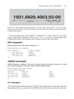
This discussion has been using the terms OSI address and NET interchangeable,
which is correct. The NET is technically a subset of a full OSI address structured as illus-
trated in Figure 4.21. The NET consists of three parts:
•
The Area-ID
•
The System-ID
•
The NET Selector (NSEL)
The NET is easier to understand when read from right to left and not from left to right as
an IP address.
4.6.3.1 NSEL
The last byte of the NET is called the selector or NSEL byte. For IS-IS, without excep-
tion, this byte must be zero. If it is not zero, then no adjacencies form. Compared to the
IP world, the NSEL is like the protocol field in the IP header, and can further multiplex
several sub-systems on a given NET. For IS-IS routers, the NSEL is always set to zero to
mean “this system”.
4.6.3.2 System-ID
Any link-state routing protocol must ensure that each node in the network can be identi-
fied uniquely. If a node cannot be identified uniquely then all subsequent functions of the
IS-IS Addressing 101
System ID
(6 Bytes)
NSEL
(1 Byte)
49.0001.1921.6821.1137.00
variable length Area
(1-13 Bytes)
AFI
(1 Byte)
FIGURE 4.21. The Network Entity Title (NET)
Unnumbered
POS2/0
Unnumbered
POS2/3
Unnumbered
GigabitEthernet4/0
Unnumbered
POS4/0
Unnumbered
GigabitEthernet5/0
49.0001.1921.6817.4012.00
Loopback0
FIGURE 4.20. IS-IS only needs one address per router