The Complete IS-IS Routing Protocol- P7 ppt
Bạn đang xem bản rút gọn của tài liệu. Xem và tải ngay bản đầy đủ của tài liệu tại đây (337.26 KB, 30 trang )
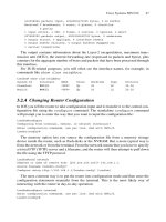
Each router in the Figure 6.13 setup forms an adjacency with the other routers, effectively
forming a full-mesh. So far, so good. Now, consider the following scenario: the ATM vir-
tual circuit between Seattle and Los Angeles breaks for some reason, as indicated by the
dotted gray line. Both Seattle and LA notice the break and therefore generate a new LSP
(incrementing the Sequence Number and removing the adjacency between Seattle and
LA). The new LSP is sent according to the flooding rule on all interfaces where there are
adjacencies in the Up state. Thus, both Seattle and LA send four copies (gray arrows) of
their new LSPs into the network. Next, the four other routers will receive the two LSPs
(white arrows). Here is where the trouble starts: because the flooding algorithm is so sim-
ple, the algorithm does not yet know that all the other routers already been have updated
and know that the adjacency between Seattle and LA is down. What follows is a multi-
plication of LSPs due to the simplicity of the flooding algorithm. All of the routers
receive the two new LSPs and re-send the LSP to all the logical interfaces except on the
ones on which they got the LSP (gray arrows). What results is that 32 LSPs are sent for
a single broken ATM VC. This does not sound too stressful for a modern router’s control
plane; however, just think if there are not six routers, but 100 routers in the network. The
problem is that the number of LSPs grows by the square of the number of routers, or in
mathematical speak O(N
2
). Thus, a single failing VC in the network may generate up to
10,000 LSP updates, all flying around in a relatively short amount of time. This is an
awful lot of stress for the control plane of a router, no matter how powerful.
Flooding 167
tx LSP
rx LSP
Seattle
Los Angeles
San Francisco New York
Atlanta
Chicago
FIGURE 6.13. ATM overlay networks and flooding stress
Things get even worse with another failure scenario: what if not a single VC, but an
entire router is going down (due to a reboot, for example)? The amount of LSPs grows
by O(N
3
). In a network of 100 routers spanning a full-mesh, this means that a single fail-
ing router generates up to 1,000,000 LSPs in a short amount of time. Ironically, 99 per
cent of the LSPs hold information that is already known by some other neighbour. So
what can be done to mitigate the dark side of flooding? The answer to this is discussed in
the next section.
6.4.2 Mesh-Groups
Let’s go back to the basic flooding algorithm and change it a little bit. Now the rule
is: Do not send out a received LSP on all the links where we have an adjacency in the Up
state. Rather, send out the LSP on some of these links. Figure 6.14 shows a router that
is not sending out an LSP on all of the possible links. Instead, some links have been pruned
off the flooding topology. The result is that all routers still see LSP updates, but the exces-
sive multiplication of LSPs is avoided. The official name for this kind of functionality is
known as Mesh-Groups and has been documented in RFC 2973. The Mesh-Group pruning
is done based on the topology of the network and is not automatic.
There are two basic concepts behind Mesh-Groups. The first concept is blocking an
interface entirely, as shown in Figure 6.14. Here, one or a set of interfaces is removed
from the flooding list. It is also very straightforward to configure on IOS and JUNOS
software, as shown in the following two configuration snippets. Both vendors share the
same spirit in their implementation of the Mesh-Group functionality. The LSP flooding
in both vendors’implementations is an interface property. In IOS, you configure everything
at the physical/logical interfaces prepended by the keyword isis. In JUNOS software,
all the logical interfaces can be referenced directly under the protocols isis
interface configuration branch, which is very practical, as the relevant information
is then at one place.
168 6. Generating, Flooding and Ageing LSPs
tx LSP
rx LSP
Pruned "flooding" links
FIGURE 6.14. Mesh-Group blocks remove certain links from the flooding topology
IOS configuration
In IOS, LSP flooding can be reduced using the isis mesh-group blocked configuration
command in interface-configuration mode, as shown in the following:
London# show running-config
[… ]
interface atm 1/2.1
ip router isis
isis mesh-group blocked
[… ]
In JUNOS the configurations statement is very similar. The first flavour of Mesh-
Groups can be enabled by use of the mesh-group blocked config-uration directive
under the protocols isis interface <interface-name> configuration
hierarchy, as shown in the following:
JUNOS software configuration
hannes@Frankfurt> show configuration
[… ]
protocols {
isis {
interface at-4/0/0.200 {
mesh-group blocked;
}
}
}
[… ]
You may ask why the word Group is contained in Mesh-Group. So far we have not con-
figured a Group number. What is the Group number related to? This number is related to the
refined version of Mesh-Groups where the flooding is not turned off entirely for an interface.
Some LSPs are still sent. How is this second flavour of Mesh-Groups configured? First, all
the logical interfaces on an IS-IS router have to be organized in groups of interfaces. In
Figure 6.15 you can see that the first three interfaces have been grouped together in Mesh-
Group #11 and the second three interfaces have been grouped together in Mesh-Group #47.
Once an LSP is received over a logical interface (white arrow), the IS-IS router first deter-
mines the Mesh-Group number that the receiving interface belongs to. In our example the
receiving interface belongs to Mesh-Group #11. When this LSP is now flooded to all neigh-
bours, the router does flood the LSP on interfaces belonging to that specific group (Mesh-
Group #11 with the gray arrows). This solves the multiplicative effect of basic flooding.
The second flavour of Mesh-Groups that has just been described can be configured in
a similar way on IOS and in the JUNOS software. The only difference here is that a
Mesh-Group Number replaces the keyword blocked. Similar to the mesh-group
blocked command, this is configured under interface configuration mode.
Flooding 169
In IOS, LSP flooding can be reduced according to the second flavour of Mesh-groups
using the isis mesh-group <group-number> configuration command in interface-
configuration mode, as shown in the following:
IOS configuration
London# show running-config
[… ]
interface atm 1/2.1
ip router isis
isis mesh-group 11
interface atm 1/2.2
ip router isis
isis mesh-group 11
interface atm 1/2.3
ip router isis
isis mesh-group 11
[… ]
In JUNOS, the Mesh-Group Number replaces the blocked statement. The
second flavour of Mesh-Groups can be enabled by use of the mesh-group <group-
number> configuration directive under the protocols isis interface
<interface-name> configuration hierarchy, as shown in the following:
JUNOS software configuration
hannes@Frankfurt> show configuration
[… ]
protocols {
isis {
interface at-4/0/0.100 {
mesh-group 11;
}
170 6. Generating, Flooding and Ageing LSPs
Mesh group #11
Mesh group #47
tx LSP
rx LSP
F
IGURE 6.15. Mesh-Groups relay an LSP only to interfaces inside the same Mesh-Group
Flooding 171
interface at-4/0/0.101 {
mesh-group 11;
}
interface at-4/0/0.102 {
mesh-group 11;
}
}
}
[… ]
Mesh-Groups help to reduce the flooding explosion in densely meshed environments.
However, keep in mind that flooding is a necessity to get information across the internal
network. In a sense, it is “too-much” flooding that causes harm. However, a “too-little”
flooding strategy can cause harm in a different way. Thus, be very careful when setting
up Mesh-Groups. Mesh-Groups cannot be so “tight” that they result in desynchronized
link-state databases. In Chapter 8 you will learn about the impact of desynchronized
link-state databases and what can be done to avoid them. At the end of the chapter, a
refinement of ISO 10589 is presented to make sure that routers that have been acciden-
tally pruned off the flooding topology (due to a wrong Mesh-Group configuration, for
example) still receive good information for synchronization.
Although Mesh-Groups must be hand-configured by a network administrator, it is
easy to determine if Mesh-Groups are needed by looking at the statistics that IOS and the
JUNOS software can provide. For example, the relevant IS-IS statistics can be displayed
using the show clns traffic command, as shown in the following:
IOS command output
Amsterdam# show clns traffic
[… ]
IS-IS: Time since last clear: never
IS-IS: Level-1 Hellos (sent/rcvd): 115/19
IS-IS: Level-2 Hellos (sent/rcvd): 120/14
IS-IS: PTP Hellos (sent/rcvd): 0/0
IS-IS: Level-1 LSPs sourced (new/refresh): 10/0
IS-IS: Level-2 LSPs sourced (new/refresh): 14/0
IS-IS: Level-1 LSPs flooded (sent/rcvd): 2/2
IS-IS: Level-2 LSPs flooded (sent/rcvd): 3/2
IS-IS: LSP Retransmissions: 0
IS-IS: Level-1 CSNPs (sent/rcvd): 0/2
IS-IS: Level-2 CSNPs (sent/rcvd): 3/0
IS-IS: Level-1 PSNPs (sent/rcvd): 0/0
IS-IS: Level-2 PSNPs (sent/rcvd): 0/0
IS-IS: Level-1 DR Elections: 3
IS-IS: Level-2 DR Elections: 2
IS-IS: Level-1 SPF Calculations: 7
IS-IS: Level-2 SPF Calculations: 7
172 6. Generating, Flooding and Ageing LSPs
IS-IS: Level-1 Partial Route Calculations: 0
IS-IS: Level-2 Partial Route Calculations: 0
IS-IS: LSP checksum errors received: 0
IS-IS: Update process queue depth: 0/200
IS-IS: Update process packets dropped: 0
[… ]
In every case, a big disparity between the LSPs being sent and the LSPs being received
is an indication that there is excess flooding in the network that needs to be controlled via
Mesh-Groups.
In the JUNOS software, you can display the global lS-IS statistics using the show isis
statistics command. Watch for a disparity between LSPs being sent and received:
JUNOS software command output
hannes@Frankfurt> show isis statistics
IS-IS statistics for Frankfurt:
PDU type Received Processed Drops Sent Rexmit
LSP 220201 220201 0 152846 381
IIH 5640823 5640823 0 3762071 0
CSNP 5486953 5486953 0 9893412 0
PSNP 32766 32766 0 192857 0
Unknown 0 0 0 0 0
Totals 11380743 11380743 0 14001186 381
Total packets received: 11380743 Sent: 14001567
SNP queue length: 0 Drops: 0
LSP queue length: 0 Drops: 0
SPF runs: 121371
Fragments rebuilt: 336
LSP regenerations: 151
Purges initiated: 0
Mesh-Groups solved a big problem in ATM or Frame-Relay overlay networks of the
mid-1990s. However, today Mesh-Groups are of limited use because ATM and FR trans-
port networks connecting routers have gone away for the most part. Today, routers are
typically interconnected by packet-over-SONET/SDH links in a sparse-meshed fashion.
A typical core router these days has on average no more than four or five interfaces facing
other core routers. In these environments, Mesh-Groups are a nice tuning capability, but
not the necessity they were only a few years ago when networks were melting down in
the absence of a sound LSP flooding scheme.
6.5 Network-wide Purging of LSPs
The flooding of LSP updates the network with the most accurate state information. The
link-state database is therefore continually increasing as new or updated information is
added to it. If a link is down, issue a new LSP. When it comes back up, issue another new
LSP. So far there have been no negative LSPs that make the database shrink in size. But
what if IS-IS wants to remove a router from the distributed link-state database in all of
the other routers in the network? There is always the option to wait until the LSP ages
out, but that can take up to 65,535 seconds (18 hours, 12 minutes). For certain events,
such as router removal, IS-IS needs to have the capability to issue a negative LSP update.
This negative LSP, or purge LSP, exists and is a “crippled” version of the original LSP.
All the purge LSP contains is the LSP header without any further information. The
Header and the Checksum fields of the purge LSP header are set to zero to indicate that
this is a purge. This negative LSP update, which is called a network-wide purge, is used
for a variety of events. One of these events is DIS election.
6.5.1 DIS Election
On IS-IS broadcast links there is at least one router performing a special function. This
IS-IS router is called the Designated Intermediate System (DIS). The role of the DIS
was first discussed in Chapter 5. Each DIS borrows an ID that is unique across the net-
work from the LAN on which it is the DIS. The DIS floods that LAN-ID throughout
the network to tell other routers that there is connectivity to the LAN. Now, if the DIS is
changed (re-elected) due to changes, such as a higher DIS election priority or the
time-out of the old DIS, then the new DIS must generate a new LAN-ID and flood this
throughout the network. The has-been DIS needs to remove the old LAN-ID from
the network in order to ensure that it does not lead to corrupt network information.
Figure 6.16 shows the chain of LSPs that are generated to accomplish this. In order
to remove the stale LSP from the former DIS, the old DIS generates an LSP with the
sequence number incremented by one, but with the Checksum and Lifetime set to
zero. Each router that receives this purge LSP will remove the referenced LSP-ID from
its link-state database.
Network-wide Purging of LSPs 173
Local LAN
Old
pseudonode
Old DIS
New
pseudonode
Old DIS
FIGURE 6.16. At DIS re-election the old pseudo node LSP gets purged
6.5.2 Expiration of LSPs
Whenever a router ages-out an LSP whose Lifetime has become zero, it needs to tell the
other routers that the LSP has been aged out. Recall that each router has an internal clock
and those clocks are subject to clock drifts. At the same time, all the routers in a given IS-
IS level fundamentally rely on the fact that its link-state database is synchronized with all
others. So for further robustness in the face of clock drift, the first router that detects that
an LSP’s Lifetime has gone to zero, initiates a network-wide purge of that expired LSP.
Lifetime expiration of LSPs is common for routers that have been removed from the net-
work for one reason or another. Recall that under normal conditions, each LSP gets
refreshed by the Originator before it expires and therefore should never countdown the
Lifetime field to zero. This should only happen during the purge of an LSP.
If a router purges an LSP from the link-state database, the LSP is not removed imme-
diately. Instead, the LSP is retained for a ZeroAgeLifetime of 60 seconds. Keeping the
purged LSP for 60 seconds ensures that an LSP is not re-learned (for instance) through
an adjacency that has been Down and is now transitioning to Up again.
You can recognize a purged LSP that is still in the database if its Lifetime value is in
brackets. This is similar to the accounting world, where red numbers are in brackets as
well. And this is exactly what the User Interfaces do as well: they essentially show you a
zombie – an LSP that is already dead but we keep it alive for visibility, helping us in the
troubleshooting case.
IOS command output
Amsterdam# show isis database
[… ]
IS-IS Level-1 Link State Database:
LSPID LSP Seq Num LSP Checksum LSP Holdtime ATT/P/OL
New-York.02-00 0x00002fb1 0x6f71 (23) 1/0/0
[… ]
JUNOS software command output
hannes@New-York> show isis database
IS-IS level 1 link-state database:
LSP ID Sequence Checksum Lifetime Attributes
New-York.02-00 0x2fb1 0x6f71 (48) L1 Attached
[… ]
4 LSPs
Typically you do not see much purged LSPs in your database as this is a very rare case
(DIS routers do not change very often). However, if you see a lot of bracketed LPSs or
one LSP always containing a bracketed Lifetime then probably a malicious event like a
flood-purge storm is raging because of duplicate System-IDs.
174 6. Generating, Flooding and Ageing LSPs
6.5.3 Duplicate System-IDs
Whenever a router receives an LSP that contains its own System-ID as Originator, and
the router is sure that it did not generate this LSP, the router must assume that there is
another router on the network that is configured with a duplicate System-ID. All the
receiving router can do is to log this event and generate a purge LSP. The other router will
most likely try to re-originate this LSP with a higher Sequence Number. Of course, this
purge process needs to be carefully paced. Otherwise a flood-purge-storm will start to
rage as the two routers continually try to update and purge each other’s wrong LSP. You
will see in the next section how these storms can be prevented. Actually, the LSP will be
purged because duplicate System-IDs are also an obstacle for a clean SPF calculation.
This ensures that the network itself stays clean.
6.6 Flow Control and Throttling of LSPs
In link-state routing protocols, the implementer needs to make an effort not to over-
whelm neighbours with excessive LSP updates. Excessive LSPs might churn the net-
work. In typical transport protocols such as TCP there is a built-in feedback mechanism
that makes the sender slow down if the receiver feels overwhelmed. This is called flow
control. However, virtually all IGPs (including IS-IS) have no way to tell a neighbour
that the IS-IS router is busy and make the other neighbouring routers throttle down LSP
transmissions. It is beyond the scope of this book as to why the protocol designers did not
address flow control in the IS-IS specification. But this lack of flow control means that
an IS-IS router has to carefully pace (spread out in time) LSPs toward a neighbour. In
good IS-IS implementations there are a lot of built-in throttles that make the IS-IS router
well behaved, even when the network is in a transient stage and several LSP updates are
flying around. Additionally, there are also limits for how frequently a router can originate
LSP updates. A router not only has to take care that it does not overwhelm its directly
connected neighbours, but the router needs to take care that it does not overwhelm all the
routers that are beyond the immediately adjacent neighbouring routers. Recall that all
routers in a given IS-IS level need to dedicate some resources (such as CPU cycles,
bandwidth and so on) to process and relay LSPs farther across the network. So let’s be
nice to these routers and not overload them, as we need them to distribute reachability
information of all types.
Most modern implementations of the IS-IS protocol support a variety of control knobs
that makes an IS-IS router slower instead of faster. Realize that going slower when there
are transient conditions or LSP storms is the only option that a router has left if the router
is to continue running. There are a couple of big “Must-Not’s” that an implementation of
IS-IS should never do.
We must not trash our neighbours. IS-IS Hellos must always be sent. If a router does
not send IS-IS Hellos in time, the adjacency times out. Losing an adjacency in transient
situations will additionally contribute more LSPs to a network that is already shaky to
begin with.
Flow Control and Throttling of LSPs 175
We must not forget to acknowledge LSPs of a neighbour. Even when a router is under
pressure in the form of extreme packet loads, not acknowledging an LSP update means
that after five seconds the LSP will be retransmitted. So it is much better to acknowledge
the LSP the first time before the LSP gets retransmitted. A retransmission consumes the
resources of the neighbouring router as well as the receiving router because an LSP has
to be retransmitted by the neighbour and re-processed on the receiving side as well.
So if making things slower is the only thing a router can do, exactly what kind of
events need to be made slower or throttled? The important events to throttle are in the
areas of:
•
The LSPs on an interface
•
Frequency of originating (generating) LSPs per router
•
Retransmissions on a interface
Each of these is discussed in the following sections.
6.6.1 LSP-transmit-interval
The LSP transmit interval is one form of pacing that was originally mentioned in ISO
10589. The specification says that an implementation of IS-IS should make sure not to send
more than 30 LSPs per second on a given broadcast link. Both IOS and JUNOS software
extended this requirement that LSPs are paced on every IS-IS interface type (broadcast and
point-to-point). You can tweak that throttling timer in both JUNOS software and IOS.
In IOS, LSP throttling can be enabled using the isis lsp-interval <time>
configuration command in interface-configuration mode. The time is a constant
expressed in milliseconds (ms). The default value is 33 ms. This example sets the
LSP pacing so as not to exceed 20 LSPs per second (pacing of 50 ms means 20 LSPs
per second).
IOS configuration
London# show running-config
[… ]
interface atm 1/2.1
ip router isis
isis lsp-interval 50
[… ]
In JUNOS software, the throttling of LSPs can be enabled by use of the isis lsp-
interval <time> configuration directive under the protocols isis interface
<interface-name> configuration hierarchy. The default value is 20 ms and gener-
ates 50 LSPs per second, which means that JUNOS software is contrary to the original
20 LSP-per-second specification, but this limit is fairly old in that respect. Modern routers
should easily handle 50 LSPs per second. This example sets the JUNOS software value to
the specification limit of 50 ms (20 LSPs per second).
176 6. Generating, Flooding and Ageing LSPs
JUNOS software configuration
hannes@Frankfurt> show configuration
[… ]
protocols {
isis {
interface at-4/0/0.100 {
lsp-interval 50;
}
}
}
[… ]
LSP throttling by use of the lsp-interval command is a powerful mechanism to
control the flooding pace to neighbouring routers in order to not overload them. There is
another issue that has not yet been discussed: control traffic (LSP and related packets)
may “push back” the user traffic (information packets) because control traffic always has
precedence in terms of scheduling on the router interface cards. Unfortunately, the con-
trol traffic transmission rate does not get lower on low-bandwidth interfaces such as DS0
or fractional T1/E1 line – control traffic stays the same. You can easily imagine that on a
low-bandwidth circuit transmitting 30 full-MTU sized packets does not leave much
room for other types of packets. So it would be nice if there were a way to tell the router
just to utilize a certain percentage of the interface bandwidth for control traffic. In IOS,
you can configure the bandwidth <bw> statement on a (sub)-interface so that the
router makes sure that there is not more than 50 per cent (for instance) of the interface
bandwidth utilized for LSP transmission. This is the recommended option to use for low-
bandwidth circuits.
IOS configuration
In IOS, LSP throttling is calculated automatically by setting the bandwidth parameter
in interface configuration mode – this makes sure that not more than 50 per cent (for
example) of the configured interface Bandwidth is dedicated to the routing protocol. This
example sets the total bandwidth available for IS-IS traffic to 256 Kbps, which might be
only a fraction of the total bandwidth available on the link (perhaps 2 Mbps):
London# show running-config
[… ]
interface Serial1/2
ip router isisu
bandwidth 256
[… ]
JUNOS software does not support automated calculation of LSP throttling because the
lowest-speed interface cards on a Juniper Networks router starts at T1/E1 speeds (1.5 and
2 Mbps) and it is assumed that even with an LSP pacing of 20 ms this will not consume
more than 50 per cent of the interface bandwidth. However, there may be fractional
Flow Control and Throttling of LSPs 177
T1/E1 circuits (less than the full bandwidth) configured as well, where LSP pacing might
have to be adjusted.
However, the JUNOS software lsp-interval knob really helps to solve two prob-
lems: regulating the control-traffic-to-user-traffic ratio, and protecting neighbours during
transient situations. So the lack of direct bandwidth control is not really an issue: the
same knob can be used to solve both problems.
Note that the traffic subject to this pacing was non-self-originated traffic, which is traf-
fic that has been originated by other routers, not the local router. In the next section, you
learn about pacing of self-originated LSPs that come from the local router.
6.6.2 LSP-generation-interval
Routers need to limit how fast they announce changes to the network. A router does not just
send an LSP and move on. Sending an LSP to the network essentially requests a replication
service from the network to flood the LSP. So any LSP sent consumes tremendous resources
from the network. The LSP sent may be replicated by hundreds of routers over thousands
of links. By inserting pacing rules on the individual routers, you can make sure that the net-
work does not melt down once more than one router has to say something. The ISO 10589
specification describes an architectural constant called minimumLSPGenerationInterval
that serves this purpose. In vendor’s documentation this is sometimes referred to as LSP
holddown. The IS-IS specification recommends setting this value to 30 seconds. Higher
intervals may lead to routers that are not responsive to changes in the network, whereas
lower values may generate too much churn in the network.
For a long time, IOS has implemented a 5 second holddown interval to keep a
good balance between the two extremes. Today, the frequency of LSP origination can
be controlled using the lsp-gen-interval <holddown> [<initial-wait>
<minimum-holddown>] configuration command. The first argument specifies the
time between LSP builds. This is the timer that ISO 10589 mentions and is discussed pre-
viously. The interesting thing about LSP build holddown is that this is not enforced
statically today. Modern implementations have a dynamic approach and try to strike
a balance between responsiveness and stability. So there are two LSP holddown timers:
a fast holddown and a slow holddown timer. Depending on how busy the network is, a
router switches from fast behaviour to slow behaviour. The first couple of LSP builds are
scheduled very quickly without LSP build holddown consideration. However, if more
LSP builds are requested, then the router is probably in trouble and the router backs off
to the normal slow LSP origination behaviour. The initial-wait timer specifies
how fast the router fires off an LSP after first building it. In transient situations a router
probably needs to update its LSP a few times and this initial-wait timer helps by
accumulating a few builds. Minimum-wait controls the LSP build holddown in the
fast phase.
How many LSPs need to be built until IOS switches from fast to slow behaviour? IOS
uses a technique called exponential back off to toggle gradually between the two modes.
Consider the IOS configuration snippet shown here. In IOS, there are three timers to con-
trol LSP holddown. The first timer specifies the LSP holddown in the slow phase
expressed in units of seconds. The second timer specifies how many milliseconds to wait
178 6. Generating, Flooding and Ageing LSPs
before sending the LSP. The third timer specifies the LSP holddown in the fast phase
expressed in milliseconds.
IOS configuration
London# show running-config
[… ]
router isis
lsp-gen-interval 5 200 1000
[… ]
Figure 6.17 shows the timing behaviour of the exponential back off algorithm. After
the first LSP is built it is delayed for 200 ms (second value given) until it gets sent. Next,
the holddown timer kicks in, therefore the second LSP originated will be delayed for at
least 1000 ms (a full second) as specified in the third argument of the lsp-gen-
interval configuration command. All subsequent LSP builds will be delayed by
twice the previous holddown time: 2 seconds for the third LSP, 4 seconds for the fourth,
and so on. The holddown time is limited to the first argument (5 seconds) of the lsp-
gen-interval command as a precaution that the interval does not grow to an infinite
value. So for every fast-build the LSP-Origination-Interval gets larger until it hits the
ceiling of 5 seconds. After a particular router has stopped issuing LSPs for 20 seconds,
the LSP holddown will be reset. This means that from here on any further LSP origin-
ations will receive fast holddowns again, but only for the first couple of LSPs.
The JUNOS software scheme has a two-step rate limit. First, there is a global LSP
throttling similar to the one specified in ISO 10589. All the LSPs are paced using a 20 ms
timer. Additionally, there is additional logic that damps adjacency and makes sure that
the adjacency is reliably up for some time before advertising the adjacency. The global
LSP gating is hard-coded; there is no user interface knob to change the value. The slow
LSP holddown value is a base value 10 seconds with 25 per cent jitter (timing variation)
applied. That means that subsequent LSP builds will be randomly delayed between 7.5
and 10 seconds. Jittering a timer makes the Event always happening earlier but never
later than the original base value. This variation is useful to avoid global synchronization
and the associated LSP storms and router churn. Recall that a new LSP makes all routers
do several things at the same time (flooding, SPF calculation, and more), which in turn
synchronizes the CPU peaks in a network. Smearing the CPU peaks across routers by
adding some timer jitter helps to avoid churn across all routers.
In JUNOS software, there are also a number of fast builds, which are currently hard-
coded to three fast builds of LSPs. The initial wait timer is hard-coded to 20 ms before
the LSP is sent. The reason why there are no configuration knobs is the JUNOS software
has adjacency holddown logic to make sure that the root cause of dynamic LSP changes
(adjacency changes), will be damped (suppressed). Exactly how does this adjacency
holddown logic work? After a successful three-way handshake, the router does not
declare the adjacency Up immediately. The router will wait to see if it can sustain the
LSP stress generated from the new adjacency. Each new adjacency can generate a lot of
LSPs. Just think of a partitioned network that starts to heal. The healing router brings up
Flow Control and Throttling of LSPs 179
180
F
IGURE
6.17. Exponential holddown gradually supresses LSPs, generation
2000
4000
6000
8000
10000
12000
t (ms)
0
First
LSP
build
Second LSP
build and send
First LSP
sent 200 ms
after build
1000 ms
holddown
2000 ms
holddown
Third LSP
build and send
4000 ms
holddown
Fourth LSP
build and send
32000
5000 ms
holddown (max holddown)
After 20 s fallback to fast behaviour
the adjacency and is exposed to a massive amount of new LSPs sent to it from the new
peer. In Chapter 8 you will acquire more insight as to just how IS-IS exchanges LSPs and
the mechanisms that synchronize link-state databases.
Can the router sustain the stress generated from all the new LSPs hammering at it? The
router does not know yet. Does it make sense to advertise a new LSP if the network is in
flux? Probably not – so the router delays its own LSPs until the network is quieter. Just
to be safe, the JUNOS software waits at least 20 seconds after an adjacency is declared
Up before doing anything further with the to-be-generated LSP. Next, the router starts to
measure the arrival rate of LSPs to see if things have become more stabilized. JUNOS
software still holds the adjacency down until the LSP reception rate has gone down to 5
LSPs/per 5 seconds. After the maximum holddown period of 60 seconds, which begins
after the IS-IS 3-way handshake, the adjacency will finally be advertised in the LSP.
That two-level approach (LSP gating plus adjacency holddowns) has proven to be a good
mechanism that works in a variety of networking environements. The Juniper Networks
development engineers felt that it was not necessary to expose a knob to change this behav-
iour to the user. (Knobs are good – but the knobs that I do not need are even better.)
6.6.3 Retransmission Interval
According to ISO 10589, each IS-IS router has to acknowledge LSPs within a five-
second window or else the neighbouring router will re-transmit that new LSP. A router
that is in trouble may not be able to respond within the five seconds. Therefore it makes
sense to increase that retransmission timer to higher values for lower-powered, CPU-
based routers. In JUNOS software, the five-second retransmission interval is hard coded
and cannot be changed. In Cisco IOS the retransmission interval is configurable and can
be controlled on a per-interface basis.
IOS configuration
In IOS, the retransmission timer is configurable. Setting the isis retransmit-interval
<interval> command in interface configuration mode controls this timer, as shown in the
following:
London# show running-config
[… ]
router isis
isis retransmit-interval 5
[… ]
In Cisco IOS, you can also control how fast LSPs are sent once a router is in the
retransmission window. This is another mechanism that helps a busy neighbour and
makes sure that a sender does not overwhelm the receiving router with LSPs once the
sender starts retransmitting LSPs. Here the router takes a non-acknowledgement of an
LSP previously sent as a sign of trouble and therefore throttles down the LSP transmis-
sion rate. Recall that the default LSP transmission rate in Cisco IOS is 33 ms between
LSPs. The default retransmission-throttling interval increases that value by a factor of 3,
Flow Control and Throttling of LSPs 181
up to 100 ms. That should be sufficient to back off a troubled router. It is not recom-
mended to go beyond 333 ms because the LSP pacing gets so slow that the network
becomes unresponsive in terms of reaction to changes.
In IOS, the retransmission-throttling timer is configurable. Setting the isis
retransmit-throttle-interval <interval> command in interface con-
figuration mode controls this timer.
IOS configuration
London# show running-config
[… ]
router isis
isis isis retransmit-throttle-interval 200
[… ]
6.7 Conclusion
The way in which an IS-IS implementation handles LSP dynamics separates amateur
enthusiast code from professional developer’s routing code. LSP dynamics is perhaps the
most important feature to focus on when evaluating IS-IS vendors. Interestingly, there is
almost nothing in the ISO 10589 specification that tells you how to implement IS-IS in
a scalable and robust manner. For many router startups, the lack of experience in how to
do this right has been a barrier to entrance in the high-end router market and it probably
still is. Ironically, in the world of open specifications, there are still barely a dozen routing
protocol software engineers who have the necessary experience to get the IS-IS code
right the first time. Do not be misled. I am not asserting that no other engineers but these
few can ever get IS-IS right. With enough time, and with customers willing to take the
pain to obtain that operational experience with regard to what works and what does not,
sooner or later every implementation of IS-IS can get to a level of what is called Carrier-
Class-Code. There are a number of interesting routing software approaches used by
other vendors, but these are not discussed in this book. Time and operational experience
will tell what implementation of IS-IS will finally prevail in the Internet.
182 6. Generating, Flooding and Ageing LSPs
7
Pseudonodes and Designated Routers
183
Historically routers were used to network local sub-nets to each other. Routing protocols
are optimized to run in a wide area network (WAN) environment which are typically point-
to-point links like Serial Lines, Frame Relay or ATM. Due to the popularity of Ethernet
since the mid-1980s routing protocols are required to operate and scale on broadcast cir-
cuits like Ethernet.
Broadcast networks allow multiple devices to see each other. For link-state routing
protocols like IS-IS multipoint capability means additional forms of stress in the domains
of Hello processing, database storage size dynamics like link-state database churn.
In this chapter you will learn how LAN circuits are different from p2p circuits, and
what scaling challenges there are on p2p circuits. You will learn about the pseudonode
concept, its nodal representation in the IS-IS link-state database and implications in the
SPF algorithm. Finally the purpose of a Designated Intermediate System (DIS) and its
election, pre-emption and timing details will be highlighted.
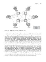
7.1 Scaling Adjacencies on Large LANs
Whenever there is a large number of routers on a LAN, lots of care must be taken. There
are several aspects of the protocol to worry about: first, if there is a large number of
speakers on the LAN there is a lot amount of Hellos to process. Just imagine a LAN with
100 IS-IS speakers generating in total 300 Hellos per second. If those 300 Hellos are
evenly spread at one Hello each 3 milliseconds, as illustrated in Figure 7.1, no problem –
this won’t stress the internal scheduling of the Router OS too much.
However, the environment, especially once it comes down to routing protocols is not
nice and far from being ideal. Therefore we may never assume ideal working conditions.
7.1.1 The Self-synchronization Problem
Murphy’s Law dictates “If things can go wrong they will go wrong”. The worst case
scenario is that 99 Hellos hit the control plane of the receiving router at once as shown
in Figure 7.2. Although the average CPU stress remains moderate if all the Hellos are
evenly spread, there could be a short time shortage of resources (buffer memory and
CPU) if a large number of Hellos arrives at once. The last line of defence in a peak load
situation is to drop incoming Hellos. Arguably the buffers should be made big enough to
absorb any peak load condition. So how big is big enough? One needs to make a trade-
off here as well. Due to stability reasons a router should not buffer an almost infinite queue
of incoming protocol packets. Processing very large queues may keep the router busy with
updates that are a few packets later withdrawn. On the other side there should be some
minimum buffer to absorb short time bursts.
The worst case was previously described as “one Router hit by all Hellos of 99 Routers
at once” and on first sight this might seem as unrealistic, artificial scenario. The reality is
that without precautions in the routing code generates Hellos there will be a resulting
effect called self-synchronization. Self-synchronization means that a router is immediately
answering with a Hello to network events like adjacency changes and new neighbours.
This behaviour tends to add up by all the speakers on the LAN and as a side-effect all the
Hellos are scheduled at the same point, which is artificially generating an unwanted form
of peak-stress followed by seconds of silence, as illustrated in Figure 7.2.
184 7. Pseudonodes and Designated Routers
Hello Received
from 1921.6800.1005
t (ms)
3 96 12 150
Hello Received
from 1921.6800.1002
Hello Received
from 1921.6800.1001
Hello Received
from 1921.6800.1003
Hello Received
from 1921.6800.1004
15
Hello Received
from 1921.6800.1006
FIGURE 7.1. Even spread Hello arrival times are an ideal, desired environment
t (ms)
3 60
Hello Received
from 1921.6800.1004
Hello Received
from 1921.6800.1003
Hello Received
from 1921.6800.1001
Hello Received
from 1921.6800.1002
Hello Received
from 1921.6800.1005
Hello Received
from 1921.6800.1006
FIGURE 7.2. A lot of Hellos hitting the control plane CPU at the same time may exhaust resources
7.1.2 Scheduling Hellos
How is the Hello scheduled? This depends on the Hold timer which controls adjacency
expiration. In order to avoid adjacency expiration each neighbouring router sends Hellos
to reset the Hold timer before it expires. In every implementation of IS-IS there is an internal
constant called the Hello-Multiplier. The Hello Interval is calculated by dividing the
Hold timer by the Hello-Multiplier. The Hold timer reset by receipt of an Hello is illus-
trated in Figure 5.3 in Chapter 5 “Neighbour Discovery and Handshaking”.
For example, a Hold timer of 30 s and a Hello-Multiplier of 3 results in a Hello Interval
of 10 s. If the system dispatches exactly each 10 s a Hello then there may be risk that the
system is starting to self-synchronize and after some local network events all routers on
the LAN will generate their Hellos at the same point in time.
To avoid the effect of self-synchronization ISO 10589 mandates to jitter timers for
scheduling Hellos.
7.1.3 Applying Jitter to Timers
What does applying a jitter to timers mean and how does it attempt to solve the self-
synchronization problem?
Applying a jitter means scheduling a Hello before it must be sent. The trick is that each
router on a LAN deducts a random time off the original Hello timer. Because each router
computes its own independent random number it is made sure that routers never send
Hellos at the same point in time.
ISO 10589 mandates to apply a 25 per cent jitter on Hellos. The 25 per cent mean that
a random number between the 0 and 25 per cent mark of the original timer is computed.
The random number should be truly random in the sense that the numbers the random-
generator produces have a uniform distribution over the entire space that it covers. For
example, a 25 per cent jitter of an underlying 10 s Hello timer would result in a random
time between 0 and 2.5 seconds. Finally the jitter is subtracted from the original timer. In
Figure 7.3 the jitter calculation is illustrated.
Both IOS and JUNOS do apply a 25 per cent jitter to their Hello timer before scheduling
the Hello for transmission. In the following tcpdump output you can see that the Timestamps
are not spaced in discrete 10 s intervals – it is always varying a little less than 10 s.
Tcpdump output
00:11:39.391338 OSI, IS-IS, L1 Lan IIH, src-id 0000.0000.0002,
lan-id 0000.0000.0001.02, prio 65, length 74
00:11:48.951503 OSI, IS-IS, L1 Lan IIH, src-id 0000.0000.0002,
lan-id 0000.0000.0001.02, prio 65, length 74
00:11:57.061652 OSI, IS-IS, L1 Lan IIH, src-id 0000.0000.0002,
lan-id 0000.0000.0001.02, prio 65, length 74
00:12:05.451811 OSI, IS-IS, L1 Lan IIH, src-id 0000.0000.0002,
lan-id 0000.0000.0001.02, prio 65, length 74
00:12:14.671953 OSI, IS-IS, L1 Lan IIH, src-id 0000.0000.0002,
lan-id 0000.0000.0001.02, prio 65, length 74
Scaling Adjacencies on Large LANs 185
Applying a jitter on the timers offers a good distribution of the scheduled Hellos among the
LAN routers over time. It is used in many other places as well. IOS and JUNOS go much fur-
ther as required by ISO 10589. For almost every one-time and periodic event the system
applies jitter. Virtually all IS-IS packet dispatching routines apply between 5 per cent and 25
per cent jitter for Hellos (IIHs), Sequence Number PDUs (SNPs) and link-state PDUs (LSPs).
As soon as the router maintains a high number of adjacencies on the LAN circuit it needs
to advertise them in its link-state PDU. A large number of LAN adjacencies raises the ques-
tion of how to represent all the router-to-router relationships in the link-state database.
7.2 Pseudonodes
See Figure 7.4 for an illustration of six routers that are located on the same LAN. The LAN
is transitive; this means that all the routers can see each other. Each of the routers gener-
ates an LSP and tells the world that it has five neighbours on the LAN by explicitly list-
ing them inside the IS Reachability TLV #2 or #22.
Any-to-any connectivity lets grow the size of the link-state database by an order of
O(N
2
). This is often referred to as the N
2
problem.
7.2.1 The N
2
Problem
Figure 7.5 illustrates the relationship between the size of IS-reach information in the
link-state database and the number of routers on a LAN. Arguably the absolute size of the
link-state database is a moderate problem compared to the dynamic effects of a full-mesh
advertisement. Every time a new router N gets on the LAN, all the other routers (N Ϫ 1)
that have been on the LAN previously need to update their LSPs to list the adjacency to
the new router. This results in a massive LSP update storm because all the routers on the
LAN need to tell the network that there has been a change in adjacencies. The same
update storm happens if a router is disconnected from the LAN.
The dynamic component (routers joining or leaving the sub-net) is a more important
problem than database storage size.
186 7. Pseudonodes and Designated Routers
10s
Hello Timer
t (s)
2 100 4 6 8
Random
jitter
1 3 5 7 9
2.5s
F
IGURE 7.3. A 25 per cent jitter on the basis of a 10 s timer results in a random Hello between
7.5 and 10 s
London POP
London-1
London-2
peer-gw vpn-gw customer-gw BRAS
IS Reachability TLV
London-1.00
LSP
cost 10
cost 10
cost 10
cost 10
cost 10
London-2.00
peer-gw.00
vpn-gw.00
customer-gw.00
BRAS.00
IS Reachability TLV
peer-gw.00
LSP
cost 10
cost 10
cost 10
cost 10
cost 10
London-1.00
London-2.00
vpn-gw.00
customer-gw.00
BRAS.00
IS Reachability TLV
London-2.00
LSP
cost 10
cost 10
cost 10
cost 10
cost 10
London-1.00
peer-gw.00
vpn-gw.00
customer-gw.00
BRAS.00
IS Reachability TLV
vpn-gw.00
LSP
cost 10
cost 10
cost 10
cost 10
cost 10
London-1.00
London-2.00
peer-gw.00
customer-gw.00
BRAS.00
IS Reachability TLV
customer-gw.00
LSP
cost 10
cost 10
cost 10
cost 10
cost 10
London-1.00
London-2.00
peer-gw.00
vpn-gw.00
BRAS.00
IS Reachability TLV
BRAS.00
LSP
cost 10
cost 10
cost 10
cost 10
cost 10
London-1.00
London-2.00
peer-gw.00
vpn-gw.00
customer-gw.00
F
IGURE
7.4. Five routers on the LAN require
O
(N
2
) storage space to accommodate all adjacencies
187
The IS-IS protocol design team was challenged to turn this N
2
problem into a linear
problem in order to scale more nicely. The solution to this problem is changing the rep-
resentation of the LAN in the link-state database. The LAN is represented by so-called
pseudonodes. Pseudonodes are comparable to the Network LSA Type #2 in OSPF and
are a very common concept in link-state routing protocols.
7.2.2 Pseudonode Representation
The solution the IS-IS design team came up with is quite straightforward: the router-to-
router relationship is modelled in the link-state database just like the real physical con-
nection relationship:
•
Each router is connected to the LAN
•
The LAN is connected to all the routers
So the idea of giving the LAN a nodal representation in the link-state database was
born. Figure 7.6 shows how the LAN is represented in the link-state database as a node
similar to a router.
The question is now who inserts the LAN node in the link-state database? How can we
make the LAN node speak and perform all the necessary tasks that a real IS-IS router has
to do, like generating, refreshing and if necessary removing LSPs?
One thing is clear: a LAN is a dumb piece of wire and has no logic to perform said tasks.
Therefore some router on the LAN has to represent the LAN in the link-state database. It
is almost like lending the LAN its voice. On each LAN circuit a Designated Intermediate
System (DIS) is elected. The DIS is a router among the IS-IS routers on the LAN, which
has, additionally to its normal duties, the purpose of representing the LAN in the link-state
database. Because the node that the DIS generates in addition to its very own node is not
a real routing node it is called a pseudonode.
Changing the representation from an any-to-any IS-reach mesh to a star topology with
the pseudonode in the middle, greatly reduces the amount of adjacencies that routers on
188 7. Pseudonodes and Designated Routers
IS-IS adjacencies on broadcast LANs
0
100
200
300
400
500
600
700
800
900
1 5 9 13172125293337
Speakers
Adcacencies
p2p adjacencies to
keep on a LAN
p2p adjacencies to
keep on a LAN with a
pseudonode
FIGURE 7.5. The number of required IS relationships grows by N
2
POP physical representation
London-1
London-2
peer-gw vpn-gw customer-gw
BRAS
LSDB nodal representation
London-1
London-2
peer-gw vpn-gw customer-gw
BRAS
LAN
F
IGURE
7.6. In the nodal representation of the link-state database the LAN becomes a node similar to a router
189
the LAN have to report. The original O(N
2
) scaling property turns into a O(N) scaling
behaviour. The LSP dynamics are improved as well. Once a new router comes online and
declares the adjacency with the DIS up only two new LSPs will be generated.
In the tcpdump output you can see that after processing the adjacency only two new
LSPs are generated. The first LSP is the pseudonode and contains the LAN to Router #3
IS Reachability. The second LSP describes the Router #3 to LAN Reachability.
Tcpdump output
On this LAN there is an established adjacency between Router #1 and #2. Next, Router
#3 comes online and after processing all the 3-way handshake and padding procedures
two new LSPs are generated.
17:37:45.769638 OSI, IS-IS, L1 CSNP, src-id 0000.0000.0001, length 99
17:37:45.799403 OSI, IS-IS, L1 Lan IIH, src-id 0000.0000.0001, lan-id
0000.0000.0001.02, prio 120, length 56
17:37:48.619494 OSI, IS-IS, L1 Lan IIH, src-id 0000.0000.0001, lan-id
0000.0000.0001.02, prio 120, length 56
17:37:50.204522 OSI, IS-IS, L1 Lan IIH, src-id 0000.0000.0002, lan-id
0000.0000.0001.02, prio 65, length 74
17:37:51.089607 OSI, IS-IS, L1 Lan IIH, src-id 0000.0000.0001, lan-id
0000.0000.0001.02, prio 120, length 56
17:37:51.273316 OSI, IS-IS, L1 Lan IIH, src-id 0000.0000.0003, lan-id
0000.0000.0003.02, prio 64, length 78
17:37:51.276579 OSI, IS-IS, L1 Lan IIH, src-id 0000.0000.0001, lan-id
0000.0000.0001.02, prio 120, length 1492
17:37:51.278286 OSI, IS-IS, L1 Lan IIH, src-id 0000.0000.0002, lan-id
0000.0000.0001.02, prio 65, length 1492
17:37:51.282142 OSI, IS-IS, L1 Lan IIH, src-id 0000.0000.0003, lan-id
0000.0000.0003.02, prio 64, length 1492
[… ]
17:37:51.364655 OSI, IS-IS, L1 Lan IIH, src-id 0000.0000.0002, lan-id
0000.0000.0001.02, prio 65, length 1492
17:37:51.365221 OSI, IS-IS, L1 Lan IIH, src-id 0000.0000.0001, lan-id
0000.0000.0001.02, prio 120, length 1492
17:37:51.367212 OSI, IS-IS, L1 Lan IIH, src-id 0000.0000.0003, lan-id
0000.0000.0001.02, prio 64, length 1492
17:37:51.370734 OSI, IS-IS, L1 Lan IIH, src-id 0000.0000.0001, lan-id
0000.0000.0001.02, prio 120, length 62
17:37:51.374205 OSI, IS-IS, L1 Lan IIH, src-id 0000.0000.0002, lan-id
0000.0000.0001.02, prio 65, length 80
17:37:51.374484 OSI, IS-IS, L1 Lan IIH, src-id 0000.0000.0003, lan-id
0000.0000.0001.02, prio 64, length 92
17:37:51.376143 OSI, IS-IS, L1 Lan IIH, src-id 0000.0000.0001, lan-id
0000.0000.0001.02, prio 120, length 62
17:37:51.379266 OSI, IS-IS, L1 Lan IIH, src-id 0000.0000.0002, lan-id
0000.0000.0001.02, prio 65, length 80
190 7. Pseudonodes and Designated Routers
17:37:51.390010 OSI, IS-IS, L1 LSP, lsp-id 0000.0000.0001.02-00,
seq 0x00000065, lifetime 65533s, length 62
17:37:51.455648 OSI, IS-IS, L1 LSP, lsp-id 0000.0000.0003.00-00,
seq 0x0000000c, lifetime 65533s, length 205
17:37:53.789837 OSI, IS-IS, L1 CSNP, src-id 0000.0000.0001, length 99
Using pseudonodes a single adjacency change triggers only two new LSPs which
greatly reduces LSP churn. Also the original N
2
problem has been reduced to a linear
problem. In the next section you will learn how the DIS allocates a unique Node-ID in
order to represent the LAN in the link-state database.
7.2.3 Pseudonode ID Selection
Based upon Figure 7.4 we will explore how the pseudonode gets its Node-ID. Figure 7.4
shows a small LAN in the POP which connects six routers: two core facing routers
(London-1 and London-2) and four customer facing access routers. Assume the London-1
core router is already the elected DIS. We will shortly explore how the DIS is elected:
assume for now that London-1 is the DIS.
Each of the six routers gets its 6-byte System-ID from the NET that was configured on all
the six routers. Figure 7.7 shows the structure of a link-state PDU ID (LSP-ID). Each LSP
in the network carries an LSP-ID in its packet header. The first 6 bytes are set to the
System-ID of the originating node. The last byte is used for Fragmentation. Fragmentation
and the notion of the Fragment-ID will be explained in Chapter 9 “Fragmentation”. The
seventh byte is called the Pseudonode-ID and it is used for Pseudonode incarnations of
the originating system. The first seven bytes is often referred to as the Node-ID.
The Pseudonode-ID number 0 has a special meaning. A zero indicates that this is the
real instance of the router. A non-zero value represents a pseudonode. Figure 7.8 shows
the nodal representation of the POP routers in the link-state database. Each square box
represents an LSP. In the header you can see the Node-ID of the originating router in two
representations. The upper line show the more convenient representation where the
6-byte System-ID gets replaced with a name. The lower line of the header also shows the
Node-ID in digit representation. The System-ID name translation service will not be dis-
cussed further because it is described in Chapter 13 “IS-IS Extensions”.
Note that all routing nodes have their pseudonode byte (7th) set to zero. Except the
London-1 (1921.6804.4001.02) Node-ID carries a non-zero pseudonode byte. This
Pseudonodes 191
System-ID
Pseudonode-
ID
Fragment-
ID
1921.6820.4003.02-00
Node-ID
LSP-ID
FIGURE 7.7. The LSP-ID dedicates one byte for pseudonode incarnations