Software Engineering For Students: A Programming Approach Part 33 docx
Bạn đang xem bản rút gọn của tài liệu. Xem và tải ngay bản đầy đủ của tài liệu tại đây (154.49 KB, 10 trang )
298 Chapter 22 ■ The spiral model
The distinctive feature of the spiral model is that it makes explicit the idea of risk.
We have seen (Chapter 1) that during software development there can be difficult prob-
lems to be overcome. The spiral model explicitly recognizes that there are uncertainties
associated with software development and that they should be dealt with as carefully as
possible. Examples of risks that are commonly experienced are:
■ the client changes some of the requirements
■ during a long development, the users’ requirements are neglected
■ someone leaves the development team
■ one of the component tasks of the development goes beyond its deadline
■ the software performs too slowly
■ the software occupies too much main memory
■ a new software development tool or technology becomes available
■ a user requirement was misunderstood
■ the target hardware configuration changes
■ an intransigent bug
■ a competitor launches a rival package onto the market.
Ideally, any process model should make provision for these and any other pitfalls.
However, the spiral model makes explicit and repeated provision for dealing with areas of
uncertainty like these and thereby minimizes the risk to the software project. Thus the
most important phase of each cycle is the risk analysis stage. Actions can then be taken to
control the project, rescue the project, or, as happens sometimes, abandon the project.
Many decisions are taken during software development, and for every decision there
is a risk that something will go wrong or a mistake will be made. The later a problem
is detected, the more effort is needed to fix it. The spiral model approach is therefore
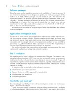
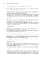
Construct
Analyze
requirements
Evaluate
Analyze risks
and plan
Figure 22.1 The spiral model
BELL_C22.QXD 1/30/05 4:26 PM Page 298
22.2 The spiral model 299
to try to discover errors frequently – at each cycle. This means they are uncovered early.
Then something can be done about them immediately.
In detail, the four steps of each cycle are as follows.
Stage 1 – risk analysis and planning
This stage is the essential ingredient of the spiral model. It consists of:
1. establishing the objectives of the product of this stage (e.g. performance, func-
tionality, ease of change)
2. identifying the constraints that affect this stage (e.g. cost, deadlines, interfaces with
other software components)
3. identifying risks
4. identifying the alternative ways of implementing this stage (buying it, reusing
something else, developing it one way, developing it another way)
5. evaluating the alternative implementation schemes against the criteria set by the
objectives and the constraints
6. deciding how to overcome the risk
7. establishing deadlines for the next stage of the project and deciding how many
people will be involved.
It is at this stage in each phase of the project that considerable flexibility can be exer-
cised. In effect, the whole of the progress of the project is reviewed and options for con-
tinuing are investigated. Use is made of whatever method is appropriate at that stage of
the project.
For example, if meeting user requirements is identified as a potential problem,
then the decision might be taken to carry out some prototyping to clarify the users
needs. (But the use of prototyping, or any other specific technique, is not part of the
spiral model.)
Stage 2 – analysis of requirements
This consists of establishing the requirements for the next stage of the project.
Stage 3 – construction
Next the development of a product is carried out. This stage may involve design, imple-
mentation, validation and verification, depending on the nature of the product. Examples
of the product of this stage are a specification, an architectural design, a prototype or a
software component.
Stage 4 – evaluation
Finally, an evaluation is used to establish whether the project is on track and whether all
the participants are happy with the plans. This leads on to the next cycle of the project.
BELL_C22.QXD 1/30/05 4:26 PM Page 299
300 Chapter 22 ■ The spiral model
Note that the number of cycles is not prescribed by the spiral model – as many cycles
as necessary are used. Further, the number of cycles is not known at the outset of a proj-
ect, but is decided as the project proceeds on the basis of the evaluations that are car-
ried out at the end of each cycle.
To illustrate how the spiral model works, we will use the example of the ATM software
described in Appendix A. Consider part of the project – the creation of a driver for the
card reader. We treat this as one spiral model cycle.
At the outset of this cycle, stage 1, the objective is confirmed as the production of a
driver to interface with the card reader, providing high-level facilities for the application.
There is a deadline (to fit in with the timescales of the project) and a budgeted cost.
Risks are as follows:
■ the driver is delivered late, so that the overall project is delayed
■ the driver is unreliable
■ the specification of the behavior of the card reader is inaccurate
■ the card reader does not work properly
■ the card reader is not available in time for testing
■ the driver is over-budget
■ the driver does not meet the specification for interfacing with the application
■ there is a shortage of person power to carry out the development.
Possible implementation plans are:
■ commission another developer
■ write the driver in-house
■ modify the primitive driver provided by the card reader supplier.
The decision as to which minimal-risk approach to use depends on factors that are
peculiar to the organization, such as the availability of appropriate people. Writing the
driver in-house may reduce some of the risks, because the development is under direct
control. If the decision is made to develop in-house, appropriate methods for design,
coding and testing are selected. (These depend on factors outside the scope of the spi-
ral model.) Finally the deadlines are decided and people allocated.
At stage 2, the detailed requirements are drawn up. This includes the specification
for the interface with the application, the specification of the card reader and the nature
of validation and verification.
At stage 3, the driver is designed, coded and tested.
At stage 4, the degree of success of the driver is assessed against its requirements.
This leads to any necessary remedial action in the first stage of the next cycle.
22.3
●
Case study
BELL_C22.QXD 1/30/05 4:26 PM Page 300
Exercises 301
Along with other process models, the spiral model does not say how each step (for
example design) is carried out. But it is common to use another process model, pro-
totyping, during one or more cycles in order to resolve uncertainty. This might be
either to clarify requirements or to establish the technical feasibility of some course
of action.
The spiral model attempts to solve some of the problems of the waterfall model,
while incorporating its best features – planning, phases, intermediate products. The spi-
ral model therefore offers greater flexibility than the waterfall model.
22.4
●
Discussion
Exercises
SELF-TEST QUESTION
22.1 Identify one advantage and one disadvantage of the spiral model.
Summary
The spiral model consists of a series of cycles. Each cycle consists of a series of steps.
At every cycle, any risks to the successful progress of the project are assessed. Then
an appropriate method is selected in order to minimize that risk. Thus the spiral
model is essentially a cautious and robust approach to development.
The spiral model consists of a repeated cycle of small steps designed to assess and
deal with risks at every cycle. Thus the spiral model is termed an iterative approach.
22.1
You are preparing a meal for special guests. What risks can you anticipate? How could
you use the ideas of the spiral model to cope with problems as they unexpectedly
arise? (Suggestions for possible disruptions are: power failure, late guests, missing
ingredients and burnt food. But make plans for other contingencies.)
22.2 Using the spiral model, plan how to carry out the development of the user interface
part of the ATM system (Appendix A).
22.3 Assess the spiral model for software development. To do this, formulate a list of cri-
teria and then use them.
•
BELL_C22.QXD 1/30/05 4:26 PM Page 301
302 Chapter 22 ■ The spiral model
For the definitive explanation of the spiral model see: Barry W. Boehm, A spiral model
of software development and enhancement, IEEE Computer, 21 (5) (May 1988),
pp. 61–72.
Answer to self-test question
22.1 Advantage: flexibility in the face of risks.
Disadvantage: absence of an early fixed plan.
Further reading
•
BELL_C22.QXD 1/30/05 4:26 PM Page 302
Prototyping is a process model that offers a solution to the problem of ensuring that
the customer gets what they want. In prototyping, the customer is presented at a very
early stage with a working version of the system. (It may not be a complete system, but
it is at least part of the system and it works.) They can check that it does what they want,
or specify modifications. The developer amends the system and demonstrates it again
and again until it does what the customer wants. Thus the main purpose of prototyp-
ing is ensuring that the user’s needs are satisfied. (We shall see that there are, however,
sometimes other goals of prototyping.)
When a new car is being developed, one or more prototypes will be individually built.
These prototypes are tested intensively before a production line is set up. It is possible
to follow a similar approach with software development. Prototyping is the practice of
building an early version of a system which does not necessarily reflect all the features
of the final system, but rather those which are of interest.
The purpose is to aid the analysis and design stages of a project by enabling users to
see very early what the system will do, that is, to facilitate validation. Users seldom have
23.2
●
Definition
23.1
●
Introduction
CHAPTER
23
Prototyping
This chapter:
■ explains how to carry out prototyping
■ explains the principles behind prototyping
■ distinguishes between evolutionary and throwaway prototyping.
BELL_C23.QXD 1/30/05 4:26 PM Page 303
304 Chapter 23 ■ Prototyping
a clear, concise understanding of their needs. The conventional specification is a narra-
tive description of a system that may be technical and time-consuming to read. The
larger the development team, including user representatives, the more difficult com-
munication becomes. Prototyping is one technique that attempts to address these prob-
lems and provide possible solutions. The benefits of developing and demonstrating a
prototype early in the software process are:
■ misunderstandings between software developers and users may be identified
■ missing facilities may be revealed
■ difficult-to-use or confusing facilities may be identified and refined
■ software developers may find incomplete and/or inconsistent requirements.
There are sometimes other objectives:
■ to create an acceptable user interface
■ a working, albeit limited, system is available quickly to demonstrate the feasibility
and usefulness of the application to management
■ user training – a prototype system can be used for training users before the final sys-
tem has been delivered
■ to establish that some new technology will provide the facilities needed (e.g. does
Java provide sufficient security for electronic transfer of funds?).
An example of using prototyping for user interface design is given in Chapter 5.
There are two types of prototype:
1. throwaway – the various versions of the system are constructed and then thrown
away. (The final system is implemented in some different way.)
2. evolutionary – an initial implementation evolves towards the final version. (The
prototype becomes the final system.)
For example, a throwaway prototype might be written very quickly in Visual Basic
to demonstrate the essential functions that a system will carry out. But then the soft-
ware might be rewritten using careful and systematic development methods.
Alternatively, an evolutionary prototype might be implemented in C# to demon-
strate to the user the main features of the system. Having checked that the system does
what is required, new features and facilities are added to the prototype, gradually trans-
forming it into its complete form.
In throwaway prototyping, the priority is to understand requirements that are
unclear and therefore requirements that are straightforward may never need to be
prototyped. In evolutionary prototyping, the first priority is to incorporate well-
understood requirements into the prototype then to move on to those requirements
that are unclear.
23.3
●
Throwaway or evolutionary?
BELL_C23.QXD 1/30/05 4:26 PM Page 304
23.4 Throwaway prototyping 305
Therefore, in summary:
■ the product of a throwaway prototype is a specification
■ the product of an evolutionary prototype is a system.
The starting point for throwaway prototyping is an outline specification for the soft-
ware. A throwaway prototype implements only those requirements that are poorly
understood. It is discarded after the desired information is learned. After the prototype
is complete, the developer writes a full specification, incorporating what was learned,
and then constructs a full-scale system based on that specification. Thus the purpose of
throwaway prototyping is the formulation of a validated specification.
Throwaway prototyping is sometimes called rapid prototyping and as the name
suggests, a rapid prototype should cost very little and take very little time to develop.
The emphasis is on using whatever methods are available to produce a system that can
be demonstrated to the user. Typically the only noticeable difference between the
prototype and the desired system is its performance, or in the volumes of data that it
handles. Rapid prototyping seems to contradict the idea of using systematic, careful
methods during development; a prototype is produced in as quick (and perhaps as
dirty) a manner as possible.
To be effective, throwaway prototyping is carried out within a systematic framework.
An overview of throwaway prototype development is shown in Figure 23.1.
The stages of throwaway prototyping are:
1. draw up an outline specification – the first step in throwaway prototyping is the
creation of an initial, often partial, specification. This specification contains areas
of uncertainty.
2. establish objectives – what is the prototype to be used for? What aspects of the pro-
posed system should it reflect? What can be learned from the prototype? The
objective may be to develop a system to prototype the user interface, to validate
functional requirements, to explore uncertain new technologies or to demonstrate
the feasibility of the application to management. The same prototype cannot meet
all objectives. The areas that are most often prototyped are the user interface, and
uncertain or vague functions.
3. select functions – the next stage is to decide what to put into and what to leave out
of the prototype. This is determined by the objectives of the system. If the purpose
of prototyping is to clarify users’ requirements, then the uncertain areas are the
candidates for prototyping. The development of a working model allows the devel-
opers to make sure that the solution they are proposing will satisfy the require-
ments and perform effectively. Depending on the objectives, it may be decided to
prototype all system functions but at reduced level. Alternatively a subset of system
functions may be included in the prototype.
23.4
●
Throwaway prototyping
BELL_C23.QXD 1/30/05 4:26 PM Page 305
306 Chapter 23 ■ Prototyping
4. construct prototype – speed and cost of construction of the prototype is crucial. Fast,
low-cost construction is normally achieved by ignoring the normal quality require-
ments for the final product (a “quick and dirty” approach), unless this is in conflict
with the objectives.
5. evaluate (check with the user) – the users use the prototype. This is more effective
than watching a demonstration of the software. During evaluation, inconsistencies
and shortcomings in the developer’s perception of the customer requirements are
uncovered. The prototype acts as an effective communication medium between the
developer and customer.
6. iterate (refine) – the prototype is rapidly modified, evaluation is carried out and
the process repeated until the prototype meets the objectives (usually an agreed
specification).
7. deliver the specification – the product of the prototyping process is a specifica-
tion that meets the users’ requirements. Since the working prototype has been
validated through interaction with the client, it is reasonable to expect that the
resultant specification document will be correct. When the requirements are
clearly established, the prototype is thrown away. At this stage, a different soft-
ware process model, such as the waterfall model, is employed to develop the
software.
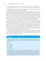
Construct
prototype
Check with
user
Refine
prototype
Deliver the
specification
Draw up an outline
specification
[User requires change]
[User happy]
Figure 23.1 Throwaway prototyping
BELL_C23.QXD 1/30/05 4:26 PM Page 306
23.5 Evolutionary prototyping 307
Users should resist the temptation to turn a throwaway prototype into a delivered
system that is put into use. The reasons for this are:
1. important system characteristics, such as performance, security and reliability, will
probably have been ignored during prototype development
2. during the prototype development, the prototype will have been changed to reflect
user needs. It is likely that these changes will have been made in an uncontrolled
way and not properly documented other than in the prototype code
3. the changes made during prototype development will probably have degraded the
architectural structure of the software. Therefore the software may be difficult and
expensive to maintain.
This type of prototyping is based on the idea of developing an initial implementation,
exposing it to user comment and refining it through repeated stages until an adequate
system has been developed.
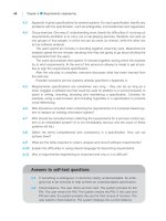
To be effective, evolutionary prototyping is carried out within a systematic frame-
work. Evolutionary prototype development is shown in Figure 23.2. Note the similar-
ities and differences between this figure and Figure 23.1.
23.5
●
Evolutionary prototyping
Construct
prototype
Check with
user
Refine
prototype
Deliver the working
system
Draw up initial
specification
[User requires change]
[User happy]
Figure 23.2 Evolutionary prototyping
BELL_C23.QXD 1/30/05 4:26 PM Page 307