Electromagnetic Field Theory: A Problem Solving Approach Part 20 pptx
Bạn đang xem bản rút gọn của tài liệu. Xem và tải ngay bản đầy đủ của tài liệu tại đây (307.94 KB, 10 trang )
Field
Boundary
Conditions
165
The
potential
in
each
region
is
1 q
(6)
E=
-V
VI
-
4,re
1
[x2+(y-d)2+z2
]/2+
[X2+(y+d)
2 +
z2]3/
2
)
(7)
VII=
y-2
q"
2
[x
xi+(y-d)i
2
+zi]+]/
EII=
-V l =
_
[2 + (Y _ d) + Z
I)
To
satisfy
the continuity
of
tangential
electric
field
at
y
0
we
have
EE
=
-V
VI
__
(87)
EEi
=
-V V
2
With
no
surface
charge,
the
normal
component
of
D
must
be
continuous
at
y
=
0,
eIEI
= e
2
E,
1 1
>
-q
+q'=
-q"
(9)
Solving
(8)
and
(9)
for
the
unknown
charges
we
find
(2-
(81)
81
+82
2162
(10)
continuous
at
y
=
0,
The
force on
the
point
charge
q
is
due
only
to
the
field
from
image
charge
q':
q2 - 1)
3-3-4
Normal
Component
of
P
and
EE
By
integrating
the
flux
of
polarization
over
the
same
Gaus-
sian pillbox
surface,
shown
in
Figure
3-12b,
we
relate
the
discontinuity
in
normal
component
of
polarization
to
the
surface
polarization
charge
density
due
using
the
relations
surface polarization
charge
density
cr,
using
the
relations
M M
166
Polarization
and
Conduction
from
Section
3.1.2:
fsP-dS=-
odSP
2
nP
-P.
=
-o'
n
(P
2
-P
1
)
=
-ap
(12)
The
minus
sign
in
front
of
,p
results
because
of
the
minus
sign
relating
the
volume
polarization
charge
density
to
the
diver-
gence
of
P.
To
summarize,
polarization
charge
is
the
source
of
P,
free
charge
is
the
source of
D,
and
the
total
charge
is
the
source
of
eoE.
Using
(4)
and
(12),
the
electric
field
interfacial
dis-
continuity
is
n*
(E
2
-Ei)
=
n
[(D
2
-DI)-(P
2
-PI)]
af+O',
(13)
so
Eo
For
linear
dielectrics
it
is
often
convenient
to
lump
polariza-
tion
effects
into the
permittivity
e
and
never
use
the
vector
P,
only
D
and
E.
For
permanently
polarized
materials,
it
is
usually
con-
venient
to
replace
the
polarization
P
by
the
equivalent
polarization
volume
charge
density
and
surface
charge
density of
(12)
and
solve
for
E
using
the
coulombic
super-
position
integral
of
Section
2.3.2.
In
many
dielectric
prob-
lems,
there
is
no volume
polarization
charge,
but
at
surfaces
of
discontinuity
a
surface
polarization
charge
is
present
as
given
by
(12).
EXAMPLE
3-2
CYLINDER PERMANENTLY
POLARIZED
ALONG
ITS
AXIS
A
cylinder
of
radius
a
and
height
L
is
centered about
the
z
axis
and
has
a
uniform
polarization
along
its
axis,
P
=
Poi.,
as
shown
in
Figure
3-14.
Find
the
electric
field
E
and
displace-
ment
vector
D
everywhere
on
its
axis.
SOLUTION
With
a
constant
polarization
P,
the
volume
polarization
charge
density
is
zero:
p.
=
-V .
P
=0
Since
P=
0
outside
the
cylinder,
the
normal
component
of
P
is
discontinuous
at
the
upper
and
lower
surfaces
yielding
uniform
surface
polarization charges:
o,(z
=
L/2)=
Po,
Top(z
=
-L12)=
-Po
I
Field
Boundary
Conditions
167
op
=
PO
z
=-L/2
Op
=
-Po
-L/2
-L/2
5
111
eoEz
D
-P
(b)
Figure
3-14
(a)
The
electric
field
due
to
a
uniformly
polarized
cylinder
of
length
L
is
the
same
as
for
two
disks
of
surface charge
of opposite
polarity
+
Po
at
z
=
L/2.
(b)
The
perpendicular
displacement
field
D,
is
continuous
across
the
interfaces at
z
=
±
L/2
while
the
electric
field
E.
is
discontinuous.
.5)
168
Polarization
and
Conduction
The
solution
for
a
single disk
of
surface
charge
was
obtained
in
Section
2.3.5b.
We
superpose the
results
for
the
two
disks
taking
care
to
shift
the
axial
distance
appropriately
by
.
L/2
yielding
the
concise
solution
for
the displacement
field:
P
0
(
(z+
L2)
(z -
L/2)
2
•
[a
+(z
+L/2)
2
V
[a
2
+(z
-L/2)
2
]
2
The
electric
field
is
then
.
=DJeo,
IzL
>L/2
=
L(D,-Po)/eo
IzI
<L/2
These
results
can
be
examined
in
various
limits.
If
the
radius
a
becomes
very
large,
the
electric
field
should
approach that
of
two
parallel
sheets
of
surface
charge
±Po,
as
in
Section
2.3.4b:
lim
E,
=f0,
J
z
>L/2
lm
.
-Poleo,
Izi
<L/2
with a
zero
displacement
field
everywhere.
In
the
opposite
limit,
for
large
z
(z
>>a,
z
>>L)
far
from
the
cylinder,
the
axial
electric
field
dies
off
as
the
dipole
field
with
0=0
lim
E=
E
o
,
p=Powa9L
with
effective
dipole
moment
p
given
by
the
product
of
the
total
polarization
charge
at
z
=
L/2, (Poira
),
and
the
length
L.
3-3-5
Normal
Component
of
J
Applying
the
conservation
of
total
current
equation
in
Section
3.2.1
to
the
same
Gaussian
pillbox
surface
in
Figure
3-12b
results
in
contributions
again
only
from
the
upper
and
lower
surfaces
labeled
"a" and
"b":
n
(J2-J
+
(D
2
-D))
=0
(14)
where
we
assume
that
no surface
currents
flow
along
the
interface.
From
(4),
relating
the
surface
charge
density
to
the
discontinuity
in
normal
D,
this
boundary
condition
can
also
be
written
as
n*
(J9-J)+
ý=0
(15)
at
which
tells
us
that
if
the
current
entering
a
surface
is
different
from
the
current
leaving,
charge
has accumulated
at
the
1
Resistance
169
interface.
In
the
dc
steady
state
the
normal
component
of
J
is
continuous
across
a
boundary.
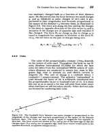
3-4
RESISTANCE
3-4-1
Resistance
Between Two
Electrodes
Two
conductors maintained
at
a
potential
difference
V
within
a
conducting medium
will
each
pass
a
total
current
I,
as
shown
in
Figure
3-15.
By
applying
the
surface
integral
form
of
charge
conservation
in
Section
3.2.1
to
a
surface
S'
which
surrounds
both
electrodes
but
is
far
enough
away
so
that
J
and
D
are
negligibly
small,
we
see
that
the
only
nonzero
current
contributions are
from
the
terminal
wires
that
pass
through
the
surface.
These
must
sum
to
zero
so
that
the
J,
Ea
-•
far
from
the
electrodes
r3
Ir*
fJ'dS=
0
S.
S
-
I
\
\
Figure
3-15
A
voltage
applied
across
two
electrodes
within an
ohmic
medium
causes
a
current
to
flow
into
one
electrode
and
out
the
other.
The
electrodes
have
equal
magnitude
but
opposite
polarity charges
so
that
far
away
the
fields
die
off
as
a
dipole
oc(1/rs).
Then,
even
though
the
surface S'
is
increasing
as
r'
,
the
flux
of
current
goes
to
zero
as
1/r.
170
Polarization
and
Conduction
currents
have
equal
magnitudes
but
flow
in
opposite
direc-
tions.
Similarly,
applying charge
conservation
to
a
surface
S
just
enclosing
the
upper
electrode
shows
that
the
current
I
entering
the
electrode
via
the
wire
must
just
equal
the total
current
(conduction
plus
displacement)
leaving
the electrode.
This
total
current
travels
to
the opposite
electrode
and
leaves
via
the
connecting
wire.
The
dc
steady-state
ratio
of
voltage
to
current
between
the
two
electrodes
in
Figure
3-15
is
defined
as
the
resistance:
R
=
ohm
[kg-m
2
-S-3-A
-
2]
(1)
I
For
an
arbitrary
geometry,
(1)
can
be
expressed
in
terms
of
the
fields
as
SEdl
LE-dl
J
dS
oE
-
dS
(2)
where
S
is
a
surface
completely
surrounding
an
electrode
and
L
is
any
path
joining
the
two
electrodes.
Note
that
the
field
line
integral
is
taken
along
the
line
from
the
high
to
low
potential
electrode
so
that
the
voltage
difference
V
is
equal
to
the
positive
line
integral. From
(2),
we
see
that
the
resistance
only
depends
on
the
geometry
and
conductivity
ao
and
not
on
the magnitude
of
the
electric
field
itself.
If
we
were
to
increase
the
voltage
by
any
factor,
the
field
would
also
increase
by
this
same
factor
everywhere
so
that
this
factor
would
cancel
out
in
the ratio
of
(2).
The
conductivity
a
may
itself
be
a
function
of
position.
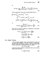
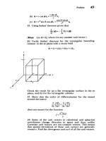
3-4-2
Parallel
Plate
Resistor
Two
perfectly
conducting
parallel
plate
electrodes
of
arbi-
trarily
shaped
area
A
and
spacing
I
enclose
a
cylinder
of
material
with
Ohmic
conductivity
oa,
as
in
Figure
3-16a.
The
current
must
flow
tangential
to
the
outer
surface
as
the
outside
medium
being
free
space
has
zero
conductivity
so
that
no
current
can
pass
through
the
interface.
Because
the
tangential
component
of
electric
field
is
continuous,
a
field
does
exist
in
the
free
space
region
that
decreases
with
increasing
distance
from
the resistor.
This
three-dimensional
field
is
difficult
to
calculate
because
it
depends
on
three
coor-
dinates.
The
electric
field
within
the
resistor
is
much
simpler
to
calculate
because
it
is
perpendicular
to
the
electrodes
in
the
x
direction.
Gauss's
law
with
no
volume
charge
then
tells
us
that
I
Depth
I
Jr
=Er, =
(a)
(b)
(c)
Figure
3-16
Simple
resistor electrode
geometries.
(a)
Parallel
plates.
(b)
Coaxial
cylinders.
(c)
Concentric
spheres.
this
field
is
constant:
dEr
v
(sE)
=
o
>-•
=>E
=
Eo
(3)
dx
However,
the
line
integral
of
E
between
the
electrodes
must
be
the
applied
voltage
v:
E.dx=
v
Eo=
v/1
(4)
The
current
density
is
then
J
=
oEoix
=
(orv/1)i
(5)
so
that
the
total
current
through
the
electrodes
is
I=
J•
dS=
(ov/)A
(6)
where
the surface
integral
is
reduced
to
a
pure
product
because
the
constant
current
density
is
incident
perpendic-
ularly
on
the
electrodes.
The
resistance
is
then
Iv
spacing
R =
.(7)
I
oA
(conductivity)
(electrode
area)
Typical resistance
values can
vary
over many
orders
of
magnitude.
If
the
electrodes
have
an
area
A
=
1
cm2
(10-
m
)
with
spacing
I = 1
mm
(10
-
3
m)
a
material
like
copper
has
a
resistance
R
-0.17
x
10-6
ohm
while
carbon
would
have
a
resistance
R
-
1.4
x
10
4
ohm.
Because
of
this
large
range
of
resistance
values
sub-units
often
used
are
micro-ohms
(1
fl=
10
- 6
f),
milli-ohms
(1
mfl=
10
-
3
1),
kilohm
(1
kfl
=
10
[l),
and
megohms
(1
Mf
=
106
fl),
where the
symbol
0
is
used
to
represent
the
unit
of
ohms.
x
Resistance
171
1L
a·
I
0
i
I
172
Polarization
and
Conduction
Although
the
field
outside
the resistor
is
difficult
to
find,
we
do
know
that for
distances
far
from
the resistor the
field
approaches
that
of
a
point
dipole
due
to
the
oppositely
charged
electrodes
with
charge density
rf(x
=
0)
=
-o-(x
=
1)
=
eEo
=
evl1
(8)
and thus
dipole
moment
p
=
-or
1
(x
=
O)Ali.
=
-eAvi,
(9)
The
minus
sign
arises
because
the dipole
moment points
from
negative
to
positive
charge.
Note
that
(8)
is
only
approximate
because
all
of
the external
field
lines
in
the
free
space
region must
terminate on
the
side
and
back
of
the
electrodes
giving
further
contributions
to
the
surface
charge
density.
Generally,
if
the electrode
spacing
I
is
much
less
than
any
of
the electrode
dimensions,
this
extra
contribution
is
very
small.
3-4-3
Coaxial
Resistor
Two
perfectly
conducting
coaxial
cylinders
of
length
1,
inner
radius
a, and
outer
radius
b
are
maintained
at
a
poten-
tial
difference
v
and
enclose
a
material
with
Ohmic
conduc-
tivity
or,
as
in
Figure
3-16b.
The
electric
field
must
then
be
perpendicular
to
the
electrodes
so
that
with
no
free
charge
Gauss's
law
requires
S"
(eE)=
0l•
(rE r) = 0
4
E
,
= c
(10)
rr
r
where
c
is
an
integration
constant
found
from
the
voltage
condition
SErdr
=
c
In
r
=vcc
(l)
The
current
density
is
then
or
J,=
-E,=
(12)
r
In
(bla)
with
the
total
current
at
any
radius
r
being
a
constant
I=
fJr
d4
dz
=
av2
(13)
=o
0
o
in
(b/a)
so
that
the
resistance
is
v
In
(bla)
R
(14)
I
2?'ol
Capacitance
173
3-4-4
Spherical
Resistor
We
proceed
in
the
same
way
for
two
perfectly
conducting
concentric
spheres
at
a
potential
difference
v
with
inner
radius
R
1
and
outer
radius
R
2
,
as
in
Figure
3-16c.
With
no
free
charge,
symmetry
requires
the
electric
field
to
be
purely
radial
so
that
Gauss's
law
yields
ia
c
V
-
(eE)=
0•7r(r
E,)=
O E,=
r
(15)
where
c
is
a
constant
found
from
the
voltage
condition
as
E,dr
=
- =
v (16)
S
R(1R,
-/R
2
)
The
electric
field
and
current
density
are
inversely
pro-
portional
to
the square
of
the
radius
],
=
oE,
= 2(
R
(17)
"(1/RI-
1/R2)
so
that
the
current
density
is
constant
at any
radius
r
2*
4tro
I=
2
=
Jr
2
sin
0
dO
do
=
(1/R-
(18)
with
resistance
v
(1/RI-1/R2)
R
(19)
I
4
7rT
3-5
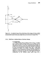
CAPACITANCE
3-5-1
Parallel
Plate
Electrodes
Parallel
plate
electrodes
of
finite
size
constrained
to
poten-
tial
difference
v
enclose
a
dielectric
medium
with
permittivity
e.
The
surface
charge
density
does
not
distribute
itself
uni-
formly,
as
illustrated
by
the
fringing
field lines
for
infinitely
thin
parallel
plate
electrodes
in
Figure
3-17a.
Near
the edges
the
electric
field
is
highly
nonuniform
decreasing
in
magni-
tude
on
the
back side
of
the
electrodes.
Between
the
elec-
trodes,
far
from
the
edges
the
electric
field
is
uniform,
being
the
same
as
if
the
electrodes
were
infinitely
long. Fringing
field
effects
can
be
made
negligible
if
the
electrode
spacing
I is
much
less
than
the
depth
d
or
width
w.
For
more
accurate
work,
end
effects
can be
made
even
more
negligible
by
using
a
guard
ring
encircling
the
upper
electrode,
as
in
Figure
3-17b.
The
guard
ring
is
maintained
at
the
same
potential
as
the
electrode,
thus
except
for
the
very
tiny
gap, the
field
between
M
ýýl
174
Polarization
and
Conduction
x
,
Area
A
0
I+++++++++++++++++++++++++++++++++++++++++++++++
(b)
Figure
3-17
(a)
Two
infinitely
thin
parallel plate electrodes
of
finite
area
at
potential
difference
v
have
highly
nonuniform
fields
outside the
interelectrode
region.
(b)
A
guard ring around
one electrode
removes
end
effects
so
that
the
field
between
the
electrodes
is
uniform.
The
end
effects
now
arise
at
the edge
of
the
guard
ring,
which
is
far
from
the
region
of
interest.
I .