Electromagnetic Field Theory: A Problem Solving Approach Part 26 pptx
Bạn đang xem bản rút gọn của tài liệu. Xem và tải ngay bản đầy đủ của tài liệu tại đây (316.86 KB, 10 trang )
Electrostatic
Generators
225
n
=
no.
of
segm
entering
dom
per
second
Charges
induced
onto
a
segmente
belt
q
=
-Ci
V
+
C v
+V-
(a)
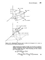
Figure
3-38
A
modified
Van
de
Graaff
generator
as
an
electrostatic
induction
machine.
(a)
Here
charges
are induced
onto
a
segmented
belt
carrying
insulated
conductors
as
the
belt
passes
near
an
electrode
at
voltage V.
(b)
Now
the
current
source
feeding
the
capacitor
equivalent
circuit
depends
on
the
capacitance
Ci
between
the
electrode
and
the
belt.
Now
the
early
researchers
cleverly
placed
another
induction
machine
nearby
as
in
Figure
3-39a.
Rather
than
applying
a
voltage
source,
because
one
had
not
been invented
yet,
they
electrically
connected
the
dome
of
each
machine
to
the
inducer
electrode
of
the
other.
The
induced charge
on
one
machine
was
proportional
to
the
voltage
on
the
other
dome.
Although
no
voltage
is
applied,
any
charge
imbalance
on
an
inducer
electrode
due
to
random
noise
or
stray
charge
will
induce
an
opposite
charge
on
the
moving
segmented
belt
that
carries
this
charge
to
the
dome
of
which
some
appears
on
the
other
inducer
electrode
where
the
process
is
repeated
with
opposite
polarity
charge.
The
net
effect
is
that
the
charge
on
the
original
inducer
has
been
increased.
More
quantitatively,
we
use
the
pair
of
equivalent
circuits
in
Figure
3-39b
to
obtain
the coupled equations
-
nCiv,
=
Cdv,
nCiV2
=
C
(2)
dt
dt
where
n
is
the
number
of
segments
per
second
passing
through
the
dome.
All
voltages
are
referenced
to
the
lower
pulleys
that
are
electrically
connected
together.
Because
these
I
i
=
-
1Ci
Polarization
and
Conduction
Figure
3-39
(a)
A
generate their
own
coupled
circuits.
pair
of
coupled
self-excited
electrostatic
induction
machines
inducing
voltage.
(b)
The
system
is
described
by
two
simple
are linear constant
coefficient
differential
equations,
the
solu-
tions
must
be
exponentials:
vl
=
e71 e
st,
v2
=
V^
2
e'
Substituting
these
assumed
solutions
into
(2)
yields
the
following
characteristic
roots:
s
=
:s=
:+
C
C
so
that
the general
solution
is
vi
=
A,
e(Mci/c)t
+A
e,
-(
"CiC)9
v2
=
-A,
e
(nc/c)t
+
A
2
e-(nc.ic)
where
A
and
A
2
are
determined
from
initial
conditions.
The
negative
root
of
(4)
represents
the
uninteresting
decaying solutions
while
the
positive
root
has
solutions
that
grow
unbounded
with
time.
This
is
why
the
machine
is
self-
excited.
Any initial voltage
perturbation,
no
matter
how
small,
increases
without
bound
until
electrical
breakdown
is
reached.
Using
representative
values
of
n
=
10,
Ci
=
2
pf,
and
C=
10
pf,
we
have
that
s
= -2
so
that
the
time
constant
for
voltage
build-up
is
about
one-half
second.
226
I
1_1
Electrostatic
Generators
227
Collector
-
Conducting
Cdllecting
brush
strips
brushes
Grounding
Inducing
brush
electrode
Front
view
I
nducing
electrodes
Side
view
Figure
3-40
Other
versions
of
self-excited
electrostatic
induction
machines
use
(a)
rotating
conducting
strips
(Wimshurst
machine)
or
(b)
falling
water
droplets
(Lord
Kelvin's
water dynamo).
These
devices
are
also
described
by
the
coupled
equivalent
circuits
in
Figure
3-39b.
The
early
electrical
scientists
did
not
use
a
segmented
belt
but
rather
conducting
disks
embedded
in
an
insulating
wheel
that
could
be
turned
by
hand,
as
shown
for
the
Wimshurst
machine
in
Figure
3-40a.
They
used
the
exponentially
grow-
ing
voltage
to
charge
up
a
capacitor
called
a
Leyden
jar
(credited
to
scientists
from
Leyden,
Holland),
which
was
a
glass
bottle
silvered
on
the
inside
and
outside
to
form
two
electrodes
with
the
glass
as
the
dielectric.
An
analogous
water
drop
dynamo
was
invented
by
Lord
Kelvin
(then
Sir
W.
Thomson)
in
1861,
which
replaced
the
rotating
disks
by
falling
water
drops,
as
in
Figure
3-40b.
All
these
devices
are
described
by
the
coupled
equivalent
circuits
in
Figure
3-39b.
3-10-3
Self-Excited
Three-Phase
Alternating
Voltages
In
1967,
Euerle*
modified
Kelvin's
original
dynamo
by
adding
a
third
stream
of
water
droplets
so
that
three-phase
*
W.
C. Euerle,
"A
Novel
Method
of Generating
Polyphase
Power,"
M.S.
Thesis,
Massachusetts
Institute
of
Technology,
1967.
See
also
J.
R.
Melcher,
Electric
Fields
and
Moving
Media,
IEEE
Trans.
Education
E-17
(1974),
pp.
100-110,
and
the
film
by
the
same
title
produced
for
the
National
Committee
on
Electrical
Engineering
Films
by
the
Educational
Development
Center,
39
Chapel
St.,
Newton,
Mass.
02160.
Polarization
and
Conduction
alternating
voltages
were
generated.
The
analogous
three-
phase
Wimshurst
machine
is
drawn
in
Figure
3-41a with
equivalent
circuits
in
Figure
3-41
b.
Proceeding
as
we
did
in
(2)
and
(3),
-nC
i
v
=
C
dV
2
dvT
-
nv2sy
=
C ,
dr
dv,
-
nCiv3
=
C-,
dr'
vi=
V
s
e
V
2
=
V
2
s e
equation
(6)
can
be
rewritten
as
nCi
Cs nC,
JVsJ
Figure
3-41
(a)
Self-excited
three-phase
ac
Wimshurst
machine.
(b)
The
coupled
equivalent
circuit
is
valid
for
any of
the
analogous
machines
discussed.
228
_·
ElectrostaticGenerators
229
which
reguires
that
the
determinant
of
the
coefficients
of
V
1
,
V
2
,
and
Vs
be
zero:
(nC)
3
+(C
+(s)
3
=0
=
(nC
1 1
i
1)
1s
(nCQ
\,
e
i
(7T
m
(
Xr-l
,
r=
1,2,
3
(8)
C
nCi
C
S2,3=!C'[I+-il
2C
where
we
realized
that
(-
1)1/
s
has
three
roots
in
the
complex
plane.
The
first
root
is
an
exponentially
decaying
solution,
but
the
other
two
are
complex
conjugates
where
the
positive
real
part
means
exponential
growth
with
time
while
the
imaginary
part
gives
the frequency
of
oscillation.
We
have
a
self-excited
three-phase
generator
as
each
voltage
for
the
unstable
modes
is
120"
apart
in
phase
from
the
others:
V
2
V
3 1
V
nC
_(+-j)=ei(/)
(9)
V
1
V
2
V3
Cs
2
,•
Using
our
earlier
typical values
following
(5),
we
see
that
the
oscillation
frequencies are
very
low,
f=(1/2r)
Im(s)
=
0.28
Hz.
3-10-4
Self-Excited
Multi-frequency
Generators
If
we
have
N
such
generators,
as
in
Figure
3-42,
with
the
last
one
connected
to
the
first
one,
the
kth
equivalent
circuit
yields
-nCi•V,
=
CsVk+l
(10)
This
is
a
linear
constant
coefficient
difference
equation.
Analogously
to
the
exponential
time solutions
in
(3)
valid
for
linear
constant
coefficient
differential equations,
solutions
to
(10)
are
of
the
form
V
1
=AAk
(11)
where
the
characteristic
root
A
is
found
by
substitution
back
into
(10)
to
yield
-
nCiAA
k
=
CsAA
'+•A
=
-
nCilCs
Polarization
and
Conduction
Figure
3-42
Multi-frequency,
polyphase
self-excited
equivalent circuit.
-Wmh=
dvc
1t
WnCin wCidt
Wimshurst
machine
with
Since
the
last
generator
is
coupled
to
the
first
one,
we
must
have
that
VN+I
=
Vi
*
N+'
=A
>AN= 1
AA
=:
lIIN
j2i•/N
r=1,
2,3,
,N
where
we
realize
that
unity
has
N
complex
roots.
The
system
natural
frequencies
are
then
obtained
from
(12)
and
(13)
as
nCA
nCi
-i2AwN
CA
CT
(14)
We see
that
for
N=
2
and
N=
3
we
recover
the
results
of
(4)
and
(8). All
the roots
with
a
positive
real
part
of
s
are
unstable
and
the
voltages
spontaneously
build
up
in
time
with
oscil-
lation
frequencies
wo
given
by
the
imaginary
part
of
s.
nCi
o0=
I
Im
(s)l
=-
I
sin
2wr/NI
(15)
C
230
(13)
ProbLnus
231
d
-x_
PROBLEMS
Section
3-1
1.
A
two-dimensional
dipole
is
formed
by
two
infinitely
long
parallel
line
charges
of
opposite
polarity
±
X
a
small
distance
di,
apart.
(a)
What
is
the
potential
at
any
coordinate
(r,
46,
z)?
(b)
What
are the
potential
and
electric
field
far
from
the
dipole
(r
>>
d)?
What
is
the dipole
moment
per unit
length?
(c)
What
is
the
equation
of
the
field
lines?
2.
Find
the dipole
moment for
each
of
the
following
charge
distributions:
2
I
II
t
jL
+
X
L
+ o L X
o
d
L
-
o
L
(a)
(c)
(d)
(e)
(a)
Two
uniform
colinear
opposite
polarity
line
charges
*Ao
each
a
small
distance
L
along
the
z
axis.
(b)
Same
as
(a)
with
the
line
charge
distribution
as
A
Ao(1-z/L),
O<z<L
A
-Ao(l+z/L),
-L<z<O
(c)
Two
uniform
opposite
polarity
line
charges
*Ao
each
of
length
L
but
at
right
angles.
(d)
Two
parallel
uniform
opposite
polarity
line
charges
*
Ao
each
of
length
L
a
distance
di,
apart.
232
Polarization
and
Conduction
(e)
A
spherical
shell
with
total
uniformly
distributed
sur-
face
charge
Q
on
the
upper
half
and
-
Q
on
the
lower
half.
(Hint:
i,
=
sin
0
cos
i,.
+sin
0
sin
4$i,
+cos
Oi,.)
(f)
A
spherical
volume
with
total
uniformly
distributed
volume
charge
of
Q
in
the
upper
half
and
-
Q
on
the
lower
half.
(Hint:
Integrate
the
results of
(e).)
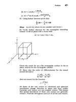
3.
The
linear
quadrapole
consists
of
two
superposed
dipoles
along
the
z
axis.
Find
the
potential and
electric
field
for
distances
far
away
from
the charges
(r
>d).
' 1 1 +
A)
. -0 -
-s'
0)
rl
r
2
rT
1
_1
1
_ +
cos
0
_
()2
(1
-3
cos2
0)
r2
r
(
r
2 r
Linear quadrapole
4.
Model
an
atom
as
a
fixed
positive
nucleus
of
charge
Q
with
a
surrounding
spherical negative
electron
cloud
of
nonuniform
charge
density:
P=
-po(1
-r/Ro),
r<Ro
(a)
If the
atom
is
neutral,
what
is
po?
(b)
An
electric
field
is
applied
with
local
field
ELo.
causing
a
slight
shift
d
between
the
center
of
the
spherical
cloud
and
the
positive
nucleus. What
is
the
equilibrium
dipole
spacing?
(c)
What
is
the
approximate
polarizability
a if
9eoELoE(poRo)<<
1?
5.
Two colinear
dipoles
with
polarizability
a
are
a
distance
a
apart
along
the
z
axis.
A
uniform
field
Eoi,
is
applied.
p
=
aEL•
a
(a)
What
is
the
total
local
field
seen
by
each
dipole?
(b)
Repeat
(a)
if
we
have
an
infinite
array
of
dipoles
with
constant
spacing
a.
(Hint:
:
1
11/n
s
•
1.2.)
(c)
If
we
assume
that
we
have
one
such
dipole
within
each
volume
of
a
s
,
what
is
the
permittivity
of
the
medium?
6.
A
dipole
is
modeled
as a
point
charge
Q
surrounded
by
a
spherical cloud
of
electrons
with
radius
Ro.
Then
the
local
__
di
Problnm
283
field
EL,
differs
from
the
applied
field
E
by
the
field
due
to
the
dipole
itself.
Since
Edip
varies
within
the
spherical
cloud,
we
use
the
average
field
within
the
sphere.
Q
P
4
3
~-
rR
0
(a
sin
th
etro
h
lu
a
h
rgn
hwta
(a)
Using
the
center
of
the
cloud
as
the
origin,
show
that
the
dipole
electric
field
within
the
cloud
is
Qri,
Q(ri,
-
di)
Edp=
-4ireoRo
+
4vreo[d
+r
2
-2rd
cos
]
S
(b)
Show
that
the
average
x
and
y
field
components
are
zero.
(Hint:
i,
=
sin
0
cos
0i,
+sin
0
sin
Oi,
+
cos
Oi,.)
(c)
What
is
the
average
z
component
of
the
field?
(Hint:
Change
variables
to
u=r
+ d
-
2rdcos
and
remember
(r
=
Ir
-dj.)
(d)
If
we
have
one
dipole
within
every
volume
of
31rR3,
how
is
the
polarization
P
related
to
the
applied
field
E?
7.
Assume
that
in
the
dipole
model
of
Figure
3-5a
the
mass
of
the
positive
charge
is
so
large
that
only
the
election
cloud
moves
as a
solid mass
m.
(a)
The
local
electric
field
is
E
0
.
What
is
the
dipole spacing?
(b)
At
t
=
0,
the
local
field
is
turned
off
(Eo
=
0).
What
is
the
subsequent
motion
of
the electron
cloud?
(c)
What
is
the
oscillation
frequency
if
Q
has
the
charge
and
mass
of
an
electron
with
Ro=
10-'
m?
(d)
In
a
real
system
there
is
always
some
damping that
we
take
to
be
proportional
to
the
velocity
(fdampin,,
=
-
nv).
What
is
the
equation
of
motion
of
the
electron
cloud
for
a
sinusoi-
dal
electric
field
Re(Eoe")?
(e)
Writing
the
driven
displacement of
the
dipole
as
d
=
Re(
de-i).
what
is
the
complex
polarizability
d,
where
Q
=
Q=
Eo?
(f)
What
is
the
complex
dielectric
constant
i
=
e,+je
6
of
the
system?
(Hint:
Define
o
=
Q
2
N/(meo).)
(g)
Such
a
dielectric
is
placed
between
parallel plate
elec-
trodes.
Show
that
the equivalent
circuit
is
a series R,
L,
C
shunted
by
a
capacitor.
What
are
C
1
,
C
2
,
L,
and
R?
(h)
Consider
the
limit
where the
electron
cloud
has
no
mass
(m
=
0).
With
the
frequency
w
as a
parameter
show
that
Re(fe
j~i
Area
A
C1
2
L
R
a
plot
of
er
versus
e,
is
a
circle.
Where
is
the
center
of
the
circle
and
what
is
its
radius?
Such a
diagram
is
called
a
Cole-Cole
plot.
(i)
What
is
the
maximum
value
of
ei
and
at
what
frequency
does
it
occur?
8.
Two
point
charges
of
opposite
sign
Q
are
a
distance
L
above
and
below
the
center
of
a
grounded
conducting
sphere
of
radius
R.
_-Q
(a)
What
is
the
electric
field
everywhere
along the
z
axis
and
in
the
0
=
v/2
plane?
(Hint:
Use
the method
of
images.)
(b)
We
would
like
this
problem
to
model
the
case
of
a
conducting sphere
in
a
uniform
electric
field
by
bringing
the
point
charges
±
Q
out
to
infinity
(L
-*
o).
What
must
the
ratio
Q/L
2
be
such
that
the
field
far
from
the
sphere
in
the
0
=
wr/2
plane
is
Eoi,?
(c)
In
this
limit,
what
is
the
electric
field
everywhere?
9.
A
dipole
with
moment
p
is
placed
in
a
nonuniform
electric
field.
(a)
Show
that
the
force
on
a
dipole
is
f
=
(p-
V)E
234
Polarization
and
Conduction
Re(vej
t)
I I
I