Electromagnetic Field Theory: A Problem Solving Approach Part 35 ppt
Bạn đang xem bản rút gọn của tài liệu. Xem và tải ngay bản đầy đủ của tài liệu tại đây (308.22 KB, 10 trang )
Forces
on
Moving
Charges
315
Moving
charges
over
a
line,
surface,
or
volume,
respectively
constitute
line,
surface,
and
volume
currents,
as
in
Figure
5-2,
where
(2)
becomes
pfv
x
Bd
V
=
J
x
B
dV
(J
=
Pfv,
volume
current
density)
odf
vxB
dS=KxB
dS
(K
=
ofv,
surface
current
density)
(3)
AfvxB
dl
=IxB
dl
(I=Afv,
line
current)
Idl=
-ev
df=l
dlx
B
(a)
B
dS
K
dS
di
>
df
= K
dSx
B
(b)
B
d
V
I
JdV
r
df
=JdVx
B
(c)
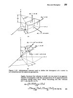
Figure
5-2
Moving
line,
surface,
and
volume
charge
distributions
constitute
currents.
(a)
In
metallic
wires
the
net
charge
is
zero
since
there
are
equal
amounts
of
negative
and
positive
charges
so
that
the
Coulombic
force
is
zero.
Since
the
positive
charge
is
essentially
stationary,
only
the
moving electrons
contribute
to
the
line
current
in
the
direction
opposite
to
their
motion.
(b)
Surface
current.
(c)
Volume
current.
316
T&
Magpeic
Fiel
The
total
magnetic force
on
a
current
distribution
is
then
obtained
by
integrating
(3)
over
the
total volume,
surface,
or
contour
containing
the
current.
If
there
is
a
net
charge
with
its
associated
electric
field
E,
the
total
force densities
include
the
Coulombic
contribution:
f=q(E+vxB)
Newton
FL=Af(E+vxB)=AfE+IXB
N/m
Fs=
ao(E+vx
B)=
oCE+Kx
B
N/m2
Fv=
p(E+vxB)=
pfE+JxB
N/m
S
In
many
cases
the net
charge
in
a
system
is
very
small
so
that
the
Coulombic
force
is
negligible.
This
is
often
true
for
conduction
in
metal
wires.
A
net
current
still
flows
because
of
the
difference
in
velocities
of
each
charge
carrier.
Unlike
the
electric
field,
the
magnetic
field
cannot change
the
kinetic
energy
of
a
moving
charge
as
the
force
is
perpen-
dicular
to
the
velocity.
It
can
alter
the charge's
trajectory
but
not
its
velocity
magnitude.
5-1-2
Charge
Motions
in
a
Uniform
Magnetic
Field
The
three
components
of
Newton's
law
for
a
charge
q
of
mass
m
moving
through
a
uniform
magnetic
field
Bi,
are
dvx
m
-
=
qv,B,
dv
dv,
m-=qvxB>
m-=
-qv.B.
(5)
dt
dt
dv,
m-
=
0
v,
=
const
The
velocity
component
along
the
magnetic
field
is
unaffected.
Solving
the
first
equation
for
v,
and
substituting
the
result
into the
second
equation
gives
us
a
single
equation
in
v.:
d v,
1
dv.
qB,
,
+oVo
=
0,
= ,
0
o=
(6)
where
oo
is
called
the
Larmor
angular
velocity
or
the
cyclo-
tron
frequency
(see
Section
5-1-4).
The
solutions
to
(6)
are
v.
=A
sin
Oot
+A
2
cos
Oot
(7)
1
dv.
v,
A,
cos
alot-A
2
sin
coot
oo
dt
Forces
on
Moving
Charges
317
where
A
and
A
2
are
found
from
initial
conditions.
If
at
t
=
0,
v(t
=
0)
=
voi,
then
(7)
and
Figure
5-3a
show
that the
particle
travels
in a
circle,
with
constant
speed
vo
in
the
xy
plane:
v
=
vo(cos
woti,
-sin
woti,)
with
radius
R
=
volwo
If
the
particle
also
has
a
velocity
component
along
the
magnetic
field
in
the
z
direction,
the
charge
trajectory
becomes
a
helix,
as
shown
in
Figure
5-3b.
t
=
(2n
+ o
(2n
+ 1)
u00
U
UU
Ca
0
Figure
5-3
(a)
A
positive
charge
q,
initially
moving
perpendicular
to
a
magnetic
field,
feels
an
orthogonal
force
putting
the
charge
into
a
circular
motion
about
the
magnetic
field
where
the
Lorentz
force
is
balanced
by
the
centrifugal
force.
Note
that
the charge
travels
in
the
direction
(in
this
case
clockwise)
so
that
its
self-field
through
the
loop
[see
Section
5-2-1]
is
opposite
in
direction
to
the
applied
field.
(b)
A
velocity
component
in
the
direction
of
the
magnetic
field
is
unaffected
resulting
in
a
helical
trajectory.
2
318
The
Magnetic
Field
5-1-3
The
Mass
Spectrograph
The
mass
spectrograph
uses
the
circular
motion
derived
in
Section
5-1-2
to
determine
the
masses
of
ions
and
to
measure
the
relative
proportions
of
isotopes,
as
shown
in
Figure
5-4.
Charges
enter
between parallel
plate
electrodes
with
a
y-
directed
velocity
distribution.
To
pick
out
those
charges
with
a
particular
magnitude
of
velocity,
perpendicular
electric
and
magnetic
fields
are
imposed
so
that the net
force
on
a
charge
is
f,=
q(E
+
vB,)
(11.)
For charges
to pass
through
the
narrow
slit
at
the
end
of
the
channel,
they
must
not
be
deflected
by
the
fields
so
that
the
force
in
(11)
is
zero.
For
a
selected
velocity
v,
=
vo
this
requires
a
negatively
x
directed
electric
field
V
Ex.=-=
-voBo
(12)
S
which
is
adjusted
by
fixing
the
applied
voltage
V.
Once
the
charge
passes
through
the
slit,
it
no
longer
feels
the
electric
field
and
is
only
under
the
influence
of
the
magnetic
field.
It
thus
travels
in
a
circle
of
radius
v
0
v
o
m
r=
(13)
wo
qBo
Photographic
plate
Figure
5-4
The
mass
spectrograph
measures
the
mass
of
an
ion
by
the
radius
of
its
trajectory
when
moving
perpendicular
to
a
magnetic
field.
The
crossed
uniform
electric
field
selects
the
ion
velocity
that
can
pass
through
the
slit.
I ·
Forces
on
Moving
Charges
319
which
is
directly
proportional
to
the
mass
of
the
ion.
By
measuring
the
position
of
the
charge
when
it
hits
the
photo-
graphic
plate,
the
mass
of
the
ion
can
be
calculated.
Different
isotopes
that
have
the
same
number
of
protons but
different
amounts
of
neutrons
will
hit
the
plate
at
different
positions.
For
example,
if
the
mass
spectrograph
has
an
applied
voltage
of
V=
-100
V
across
a
1-cm
gap
(E.
=
-104
V/m)
with
a
magnetic
field
of
1
tesla,
only
ions with
velocity
v,=
-E/Bo
=
104
m/sec
(14)
will
pass
through.
The
three
isotopes
of
magnesium,
12
Mg
24
25
26
12
Mg
,
12
Mg
,
each
deficient
of
one
electron,
will
hit
the
photographic
plate
at
respective
positions:
2
x
10
4
N(1.67
x
10-
2
7
)
d=2r=
10'
2x
10-4
N
1.6x
10-'9(1)
0.48,
0.50,
0.52cm
(15)
where
N
is
the
number
of
protons
and
neutrons
(m
=
1.67
x
10-27
kg)
in
the
nucleus.
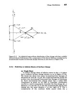
5-1-4
The
Cyclotron
A
cyclotron
brings
charged
particles
to
very
high
speeds
by
many
small
repeated
accelerations.
Basically
it
is
composed
of
a
split
hollow
cylinder,
as
shown
in
Figure
5-5,
where
each
half
is
called
a
"dee"
because
their
shape
is
similar
to
the
z
Figure
5-5
The
cyclotron
brings
ions
to
high speed
by
many
small
repeated
accelera-
tions
by
the
electric
field
in
the
gap
between
dees.
Within
the
dees
the
electric
field
is
negligible
so
that
the
ions
move
in
increasingly
larger
circular
orbits
due
to
an
applied
magnetic
field
perpendicular
to
their
motion.
320
The
Magnetic
Field
fourth
letter
of
the
alphabet.
The
dees
are
put
at
a
sinusoi-
dally
varying
potential
difference.
A
uniform
magnetic
field
Boi,
is
applied
along
the
axis
of
the
cylinder.
The
electric
field
is
essentially
zero
within
the
cylindrical
volume
and
assumed
uniform
E,=
v(t)/s
in
the
small
gap
between
dees.
A
charge
source
at
the
center
of
D,
emits
a
charge
q
of
mass
m
with
zero
velocity
at
the peak
of
the
applied
voltage
at
t
=
0.
The
electric
field
in
the
gap accelerates
the
charge
towards
D
2
.
Because
the
gap
is
so
small
the
voltage
remains
approximately
constant
at
Vo
while
the charge
is
traveling
between
dees
so
that
its
displacement
and
velocity
are
dv,
q
Vo
qVo
dt
s
sm
(16)
dy
qVot
2
v,
= y -
dt
2ms
The
charge
thus
enters
D
2
at
time
t
=
[2ms
2
/qVo]"
/2
later
with
velocity
v,
=
-/2q
Vo/m.
Within
D
2
the
electric
field
is
negligible
so
that
the charge
travels
in
a
circular
orbit
of
radius
r
=
v,/oo
=
mv/IqBo
due
to
the
magnetic
field
alone.
The
frequency
of
the
voltage
is
adjusted
to
just
equal
the angular
velocity
wo
=
qBo/m
of
the charge,
so
that
when
the
charge
re-enters
the
gap between
dees
the
polarity
has
reversed
accelerating-
the charge
towards
D
1
with
increased
velocity.
This
process
is
continually
repeated,
since
every time
the charge
enters
the
gap
the
voltage
polarity
accelerates
the
charge
towards
the opposite
dee,
resulting
in
a
larger
radius
of travel.
Each
time
the
charge
crosses
the
gap
its
velocity
is
increased
by
the
same
amount
so
that after
n
gap
traversals
its
velocity
and
orbit
radius
are
(2qnVo)
' ,
v,
/2nmVo
1
v
2
v.
=
, n
R.
=
-=
(2m
Vo)
1/2
(17)
m
-
wo
qBo
If
the
outer
radius
of
the
dees
is
R,
the
maximum speed
of
the charge
vmax
=
WoR
=
qBR
(18)
m
is
reached
after
2n
=
qB
R
2
/mVo
round
trips
when
R,
=
R.
For
a
hydrogen
ion
(q
=
1.6x
10-19
coul,
m
=
1.67
10
-
27
kg),
within
a
magnetic
field
of
1
tesla
(o
0
=
9.6
X
107
radian/sec)
and
peak
voltage
of
100
volts
with
a
cyclotron
radius
of
one
meter,
we
reach
vma,,,
9
.
6
x
10
7
m/s
(which
is
about
30%
of
the
speed
of
light)
in
about
2n
- 9.6
x
10
5
round-trips,
which
takes
a
time
=
4nir/wo,
27r/100-0.06
sec.
To
reach
this
I_· __
Forces
on
Moving
Charges
speed
with
an electrostatic
accelerator
would
require
2
mvy=qV•4
V=mvmaxm
4 8
x
106
Volts
(19)
2q
The
cyclotron
works
at
much
lower
voltages
because
the
angular
velocity
of
the
ions
remains
constant
for
fixed
qBo/m
and
thus
arrives
at
the
gap
in
phase
with
the
peak
of
the
applied
voltage
so
that
it
is
sequentially
accelerated
towards
the opposite
dee.
It
is
not
used
with
electrons
because
their
small
mass
allows
them
to
reach
relativistic
velocities close
to
the
speed
of
light,
which
then
greatly increases
their
mass,
decreasing
their angular
velocity
too,
putting
them
out
of
phase
with
the
voltage.
5-1-5
Hall
Effect
When charges
flow
perpendicular
to
a
magnetic
field,
the
transverse
displacement
due
to
the
Lorentz
force
can
give
rise
to
an
electric
field.
The
geometry
in
Figure
5-6
has
a
uniform
magnetic
field
Boi,
applied
to
a
material
carrying
a
current
in
the
y
direction.
For
positive
charges
as
for
holes
in
a
p-type
semiconductor,
the
charge
velocity
is
also
in
the
positive
y
direction,
while
for
negative
charges
as
occur
in
metals
or
in
n-type
semiconductors,
the
charge
velocity
is
in
the
negative
y
direction.
In
the
steady
state
where
the
charge
velocity
does
not
vary
with
time,
the net
force
on
the
charges
must
be
zero,
Bo
i,
=
vyBod
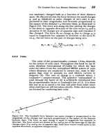
Figure
5-6
A
magnetic
field
perpendicular
to a
current
flow
deflects
the
charges
transversely
giving
rise
to
an
electric
field
and
the
Hall
voltage.
The
polarity
of
the
voltage
is
the
same
as
the
sign
of
the
charge
carriers.
týý
322
The
Magnetic
Field
which
requires the
presence
of
an
x-directed
electric
field
E+vx
B
=
0=>Ex
=
-v,Bo
(20)
A
transverse
potential
difference
then
develops
across
the
material
called
the
Hall
voltage:
V=-
Exdx
=
vBod
(21)
The
Hall
voltage
has
its
polarity
given
by
the
sign
of
v,;
positive
voltage
for
positive
charge
carriers
and
negative
voltage
for
negative
charges.
This
measurement
provides
an
easy
way
to
determine
the
sign
of
the
predominant
charge
carrier
for
conduction.
5-2
MAGNETIC FIELD
DUE
TO
CURRENTS
Once
it
was
demonstrated
that
electric
currents
exert
forces
on
magnets,
Ampere
immediately
showed
that
electric
cur-
rents
also
exert
forces
on
each
other
and
that
a
magnet
could
be
replaced
by
an
equivalent
current
with
the
same
result.
Now
magnetic
fields
could
be
turned
on
and
off
at
will
with
their
strength
easily
controlled.
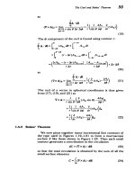
5-2-1
The
Biot-Savart
Law
Biot
and
Savart
quantified
Ampere's
measurements
by
showing
that
the
magnetic
field
B
at
a
distance
r
from
a
moving
charge
is
B
oqv
x
i,
B=
-r
2
teslas
(kg-s-
2
-A
- 1
)
(1)
as
in
Figure
5-7a,
where
go
is
a
constant
called
the
permeabil-
ity
of
free
space
and
in
SI
units
is
defined
as
having
the
exact
numerical
value
0-=
47
x
10
- 7
henry/m
(kg-m-A
-2-s
- 2
)
(2)
The
47"
is
introduced
in (1)
for the
same
reason
it
was
intro-
duced
in
Coulomb's
law
in
Section
2-2-1.
It
will
cancel
out
a
4,r
contribution
in
frequently
used
laws
that
we
will
soon
derive
from
(1).
As
for
Coulomb's
law,
the
magnetic
field
drops
off
inversely
as
the
square
of
the
distance,
but
its
direc-
tion
is
now
perpendicular
both
to
the
direction
of
charge
flow
and
to
the
line
joining
the
charge
to
the
field
point.
In
the
experiments
of
Ampere
and
those
of
Biot
and
Savart,
the charge
flow
was
constrained
as
a
line
current
within
a
wire.
If
the
charge
is
distributed
over
a
line
with
____
Magnetic
Field
Due
to
Currents'
323
'QP
Idl
B
K
dS
B
Figure
5-7
The
magnetic
field
generated
by
a
current
is
perpendicular
to
the
current
and
the
unit
vector
joining
the
current
element
to
the
field
point;
(a)
point
charge;
(b)
line
current;
(c)
surface
current;
(d)
volume
current.
current
I,
or
a
surface
with
current
per
unit
length
K,
or
over
a
volume
with
current
per
unit
area
J,
we
use
the
differential-
sized
current
elements,
as
in
Figures
5-7b-5-7d:
I
dl
(line
current)
dq
v=
K
dS
(surface
current)
J
dV
(volume
current)
The
total
magnetic
field
for
a
current
distribution
is
then
obtained
by
integrating
the
contributions from
all
the
incre-
mental elements:
_o
I
dl
x
iQp
4o
Jrdl
X
(line
current)
Co
K
dS
xiQP
4
2
prJs
-
p
(surface
current)
4o
JdVxiQP
Ao
Jv
-dip
(volume
current)
.4·n
v T2
-
324
The
Magnetic
Field
The
direction
of
the
magnetic
field
due
to
a
current
element
is
found
by
the
right-hand
rule,
where
if
the
forefinger
of
the
right hand
points
in
the
direction
of
current
and
the middle
finger
in
the direction
of
the
field
point,
then
the
thumb
points
in
the direction
of
the
magnetic
field.
This
magnetic
field
B
can
then
exert
a
force on
other
currents,
as
given
in
Section
5-1-1.
5-2-2
Line
Currents
A
constant
current
I,
flows
in
the
z
direction
along
a
wire
of
infinite
extent,
as
in
Figure
5-8a.
Equivalently,
the
right-hand
rule
allows
us
to
put
our
thumb
in
the direction
of
current.
Then
the
fingers
on
the
right
hand
curl
in
the
direction
of
B,
as
shown
in
Figure
5-8a.
The
unit
vector
in
the
direction
of
the
line
joining
an
incremental
current
element
I,
dz
at
z
to
a
field
point
P is
r %
iQp
=
i,.
cos
0
-i
sin
0
=
i, i
-
rQp
rQp
[z
2
+
r2]
1
/
2
B
•
2ra
2o11
ra
r
2ira
a
-a
-
Figure
5-8
(a)
The
magnetic
field
due
to
an
infinitely
long
z-directed
line
current
is
in
the
0
direction.
(b)
Two
parallel
line
currents
attract
each
other
if
flowing
in
the
same
direction
and
repel
if
oppositely
directed.
^ I