Electromagnetic Field Theory: A Problem Solving Approach Part 44 doc
Bạn đang xem bản rút gọn của tài liệu. Xem và tải ngay bản đầy đủ của tài liệu tại đây (291.04 KB, 10 trang )
Magnetic
Circuits
405
6-2
MAGNETIC
CIRCUITS
Various
alloys
of
iron
having
very
high
values
of
relative
permeability
are
typically
used
in
relays
and
machines
to
constrain
the
magnetic
flux
to
mostly
lie
within
the
permeable
material.
6-2-1
Self-Inductance
The
simple
magnetic
circuit
in
Figure
6-8
has
an
N
turn
coil
wrapped
around
a
core
with
very
high
relative
permeability
idealized
to
be
infinite.
There
is
a
small
air
gap
of
length
s
in
the
core.
In
the
core,
the
magnetic
flux
density
B
is
proportional
to
the
magnetic
field
intensity
H
by
an
infinite
permeability
g.
The
B
field
must
remain
finite
to
keep
the
flux
and
coil
voltage
finite
so
that
the
H
field
in
the
core
must
be
zero:
H=0
lim
B=
AH>
(1)
,B
finite
Contour
of
integration
of
S
Closed
surface
S
has
zero net
flux
through
it
raraoay S
IdW
eUValuareo lU1r
Udorl.u
curlluU
IuIruwvIy iv
turn coil
in
the
direction
of
the current
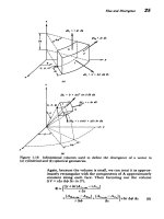
Figure
6-8
The
magnetic
field
is
zero within
an infinitely
permeable
magnetic
core
and
is
constant
in
the
air
gap
if
we
neglect
fringing.
The
flux
through
the air
gap
is
constant
at
every
cross
section
of
the
magnetic circuit
and
links
the
N
turn
coil
N
times.
406
Electromagnetic
Induction
The
H
field
can
then
only
be
nonzero
in
the
air
gap.
This
field
emanates
perpendicularly
from
the
pole
faces
as
no
surface
currents
are
present
so
that
the
tangential
component
of
H
is
continuous
and
thus
zero.
If
we
neglect
fringing
field
effects,
assuming
the gap
s
to
be
much
smaller
than
the
width
d
or depth
D,
the
H
field
is
uniform
throughout
the
gap.
Using
Ampere's
circuital
law
with
the contour
shown,
the
only
nonzero contribution
is
in
the
air
gap,
H
dl=
Hs
=
Io enlosed
=
N
(2)
where
we
realize
that
the
coil
current
crosses
perpendicularly
through
our
contour
N
times.
The
total
flux
in
the
air
gap
is
then
,oNDd
.
D
=
izoHDd
=
uo
(3)
Because
the
total
flux
through
any
closed
surface
is
zero,
sB
.
dS=
0
(4)
all
the
flux
leaving
S
in
Figure
6-8
on
the
air
gap
side
enters
the
surface
through
the
iron
core,
as
we
neglect
leakage
flux
in
the
fringing
field.
The
flux
at
any
cross
section
in
the
iron
core
is
thus
constant,
given
by
(3).
If
the
coil
current
i
varies
with
time,
the
flux
in
(3)
also
varies
with
time
so
that
a
voltage
is
induced
across
the
coil.
We
use
the integral
form
of Faraday's
law
for
a
contour
that
lies
within
the
winding
with
Ohmic
conductivity
ao,
cross
sectional
area
A,
and
total
length
I.
Then
the
current
density
and
electric
field
within
the
wire
is
J=-,
E=
-
(5)
A'
-roA
so
that
the
electromotive
force
has
an
Ohmic
part
as
well
as
a
contribution
due
to
the
voltage-across
the terminals:
Ci "
d
f
E-d=
-1-dt+
E.dI=
•
BdS
(6)
-f
b
dtJ
iR
across
in
wire
terminals
The
surface
S
on
the
right-hand
side
is
quite
complicated
because
of
the
spiral
nature
of
the
contour.
If
the
coil
only
had one
turn,
the
right-hand
side
of
(6)
would
just
be
the
time
derivative of
the
flux
of
(3).
For
two
turns,
as
in
Figure
6-9,
the
flux
links
the
coil
twice,
while
for
N
turns
the
total
flux
·
_11_1·_
·
______
~ _~__
Magnetic
Circuits
407
t
d•
t
=fB
dS
-
surface
S
Fluxinke
Flux
linked
by
a
two
turn
loopis
2
4b
4P
rte
9±
Flux linked
by
a
Nturn
coil
is
N'Z'
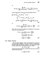
Figure
6-9
The
complicated
spiral
surface
for
computation
of
the
linked
flux
by
an
N
turn
coil
can
be
considered
as
N
single loops each
linking
the
same
flux
4.
linked
by
the
coil
is
NM.
Then
(6)
reduces
to
v
=
iR
+L
(7)
dt
where the
self-inductance
is
defined
as
L
N
= N
s
B
dS
=
1 0
N
d
henry
[kg-m
2
-A
-s
- 2
]
(8)
i
fLH
.
dl
s
For
linearly
permeable
materials,
the
inductance
is
always
independent
of
the
excitations
and
only
depends
on
the
geometry.
Because
of
the
fixed
geometry,
the inductance
is
a
constant
and
thus
was
taken
outside the
time
derivative
in
(7).
In
geometries
that
change
with
time,
the
inductance
will
also
be
a
function
of
time
and
must
remain
under
the
derivative.
The
inductance
is
always
proportional
to
the square
of
the
number
of
coil
turns.
This
is
because
the
flux
( in
the
air
gap
is
itself
proportional
to
N
and
it links
the
coil
N
times.
EXAMPLE
6-1
SELF-INDUCTANCES
Find
the
self-inductances
for the
coils
shown
in
Figure
6-10.
(a)
Solenoid
An
N
turn
coil
is
tightly
wound
upon
a
cylindrical
core
of
radius
a,
length
1,
and
permeability
At.
Flux
0
through
a
single
loop
408
Electromagnetic
Induction
Contour
of
integration
of
Ampere's
law
(magnetic
field
negligible
nlltside
coil)
utting
contour =
Ni
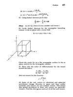
Figure
6-10
Inductances.
(a)
Solenoidal
coil;
(b)
toroidal
coil.
SOLUTION
A
current
i
flowing
in
the
wire
approximates
a
surface
current
K,
=
Ni/ll
If
the
length
I
is
much
larger
than
the
radius
a,
we
can
neglect
fringing
field
effects
at
the
ends and
the internal
magnetic
field
is
approximately
uniform and
equal
to
the surface
cur-
rent,
Ni
H.
=
K0,
=
as
we
assume
the
exterior
magnetic
field
is
negligible.
The
same
result
is
obtained
using Ampere's
circuital
law
for
the
contour
shown
in
Figure
6-10a.
The
flux
links
the
coil
N
times:
NID
NAtH,
ra
2
N
2
l,2lra
2
L=
i i 1
(b)
Toroid
AnN
turn
coil
is
tightly
wound
around
a
donut-shaped
core
of
permeability
1A
with
a
rectangular
cross
section
and
inner
and
outer
radii
R
1
and
R
2
.
No
net
current
cuts
contour
(equal
but
opposite
contributions
from
upward
and
downward
currents)
No
current
cuts
contour
\P
I
/
I
/
o
outside
0
"I.
. .
A
Iv lu|rI
Magnetic
Circuits
409
SOLUTION
Applying
Ampere's
circuital
law
to
the
three
contours
shown
in
Figure
6-10b,
only
the
contour
within
the
core
has
a
net
current
passing
through
it:
0,
r<R,
SH.
dl=H02rr=
Ni,
R,<r<R
2
0,
r>R
2
The
inner
contour
has
no
current
through
it
while
the
outer
contour
enclosing
the
whole
toroid
has
equal
but
opposite
contributions from upward and
downward
currents.
The
flux
through
any
single
loop
is
1
=
jD
H,
dr
_
DNi
R2
dr
21r
, r
pDNi
In
R
2
2,r
R,
so
that
the
self-inductance
is
N'D
gpDN
2
R
2
L
=
-
In-
i
2-7r
R
1
6-2-2
Reluctance
Magnetic circuits
are
analogous
to resistive
electronic
circuits
if we
define the
magnetomotive
force
(MMF)
9
analogous
to
the
voltage
(EMF)
as
=
Ni
(9)
The
flux
then
plays
the
same
role
as
the
current
in
electronic
circuits
so
that
we
define
the
magnetic
analog
to
resistance
as
the
reluctance:
9
N
2
(length)
(
L
(permeability)(cross-sectional
area)
which
is
proportional
to
the
reciprocal
of
the
inductance.
The
advantage
to
this
analogy
is
that
the
rules
of
adding
reluctances
in
series
and
parallel
obey
the
same
rules
as
resist-
ances.
(a) Reluctances
in
Series
For
the
iron
core
of infinite
permeability
in
Figure
6-1
a,
with
two
finitely
permeable
gaps
the
reluctance
of
each
gap
is
found
from
(8)
and
(10)
as
aso
that
theD
so
that
the
flux
is
A2a2D
(11)
(12)
_
Ni
NO
N'
921+.2
i1+ 2 i
I
+ R2
The
iron core
with
infinite
permeability
has
zero
reluctance.
If
the permeable
gaps
were
also
iron
with
infinite
permeabil-
ity,
the
reluctances of
(11)
would
also
be
zero
so
that
the
flux
••1
=
,os-
Contour
for
2
2 =
s2
evaluating Ampere's
law
.
9=Ni=t
+?2)
Depth
D
$
S
Paths
for
evaluation
of
Ampere's
circuital
Depth
D
law
which
give
us
that
He
=
H
2
=
Ni/s
Figure
6-11
Magnetic
circuits
are
most
easily
analyzed
from
a
circuit
approach
where
(a)
reluctances
in
series
add
and
(b)
permeances
in
parallel
add.
410
Electromagnetic
Induction
I
ns
i
4~
4
2
I
I
.
Nturn
V
=.F(q
+92)
I
a 2
,
-
t
.
•
-
Magnetic
Circuits
411
in
(12)
becomes
infinite.
This
is
analogous
to
applying
a
voltage
across
a
short
circuit
resulting
in
an
infinite
current.
Then
the
small
resistance
in
the
wires
determines
the large
but
finite
current.
Similarly,
in
magnetic
circuits
the
small
reluctance
of
a
closed
iron
core of
high
permeability
with
no
gaps
limits
the
large
but
finite
flux
determined
by
the
satura-
tion
value of
magnetization.
The
H
field
is
nonzero
only
in
the
permeable
gaps
so
that
Ampere's
law
yields
Hs
+ H
2
s2
=
Ni
(13)
Since
the
flux
must
be
continuous
at
every
cross
section,
(=
1
ALH
l
a
1
D
=
s
2
H
2
a
2
D
(14)
we
solve
for
the
H
fields
as
e
2
a
2
Ni
1 1_aNi
H1
=
a2
,
H2
=
(15)
1
•a12
+2a2s
1a
S2
2
+-
2
a
2
s
1
(b)
Reluctances
in
Parallel
If
a
gap
in
the
iron
core
is
filled
with
two
permeable
materials,
as
in
Figure
6-1
lb, the
reluctance
of
each
material
is
still given
by
(11).
Since
each
material
sees
the
same
magnetomotive
force,
as
shown
by
applying
Ampere's
circuital
law
to
contours
passing
through
each
material,
Ni
His
= H
2
s
=
Ni
=Hi
=
H
2
=
(16)
the
H
fields in
each
material
are
equal.
The
flux
is
then
Ni(
t
+
2)
0
=
(AHlal
+
A2H2a2)D
=
=
Ni(
+
2)
(17)
where
the permeances
01
and
-2
are just
the
reciprocal
reluctances
analogous
to
conductance.
6-2-3
Transformer
Action
(a)
Voltages
are not
Unique
Consider
two
small
resistors
R
1
and
R
2
forming
a
loop
enclosing
one
leg
of
a
closed
magnetic
circuit
with
permeabil-
ity
A,
as
in
Figure
6-12.
An
N
turn
coil
excited
on
one
leg
with
a
time
varying
current
generates
a
time
varying
flux
that
is
approximately
QD(t)=
pNAi/
1
(18)
where
I
is
the
average
length
around
the
core.
412
Electromagnetic
Induction
Cross
sectional
R
2
d4
area
A
v
2
=
-iR
2
-
o
dQe
V1
-
V2
-
dt
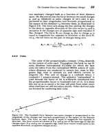
Figure
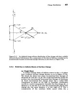
6-12 Voltages
are
not
unique
in
the
presence
of
a
time
varying
magnetic
field.
A
resistive
loop
encircling
a
magnetic
circuit
has
different
measured
voltages
across
the
same
node
pair.
The
voltage
difference
is
equal
to
the
time
rate
of
magnetic
flux
through
the
loop.
Applying Faraday's
law
to
the
resistive
loop
we
have
d•(t)
1
de
E.
dl=
i(R
+R2)=
t
=
(19)
dt
Rj+R9
dt
where
we
neglect
the
self-flux
produced
by
the
induced
cur-
rent
i
and
reverse
the
sign
on
the
magnetic
flux
term
because
D
penetrates
the
loop
in
Figure
6-12
in
the
direction opposite
to
the
positive
convention
given
by
the
right-hand rule
illus-
trated
in
Figure
6-2.
If
we
now
measured
the
voltage
across
each
resistor,
we
would
find
different
values
and
opposite
polarities
even
though
our
voltmeter
was
connected
to
the
same
nodes:
R
1
do
vl
=
iR
=
+
RI
1
+R9
dt
(20)
-RP
dep
v2
=
-iR
2
=
R
1
+R
2
dt
This
nonuniqueness
of
the
voltage
arises
because
the
elec-
tric
field
is
no
longer
curl
free.
The
voltage
difference
between
two
points
depends
on
the
path
of
the
connecting
wires.
If any
time
varying magnetic
flux
passes
through
the
contour
defined
by
the
measurement,
an
additional
contri-
bution
results.
·___
'i2 -2
Magnetic
Circuits
413
(b)
Ideal
Transformers
Two
coils
tightly
wound
on
a
highly
permeable
core,
so
that
all
the
flux
of
one
coil
links
the
other,
forms
an
ideal
trans-
former,
as
in
Figure
6-13.
Because
the
iron
core
has
an
infinite
permeability,
all
the
flux
is
confined
within
the
core.
The
currents
flowing in
each
coil,
it
and
i
2
,
are
defined
so
that
when
they
are
positive
the
fluxes
generated
by
each
coil
are
in
the
opposite direction.
The
total
flux
in
the
core
is
then
Nlil
-N
2
i2
Q
IR ~
jAA
where
2
is
the
reluctance
of
the
core
and
I
length
of
the
core.
The
flux
linked
by
each
coil
is
then
S=
Ni=
(Nii
-NIN
2
i
2
)
A
2
=
NP
=
(N
1
N
2
it
-
Ni
2
)
N12
(21)
is
the
average
(22)
Cross
sectional
ary
winding
V
1
N
1
v
2
N
2
ii
N2
vil
=
V2i
2
il
N
2
I2
NI
(a)
Figure
6-13
(a)
An ideal
transformer
relates
primary
and
secondary
voltages
by
the
ratio
of
turns
while
the
currents
are
in
the
inverse
ratio
so
that
the
inputpower
equals
the
output
power.
The
H field
is
zero
within
the
infinitely
permeable
core.
(b)
In
a
real
transformer
the
nonlinear
B-H
hysteresis
loop
causes
a
nonlinear
primary
current
it
with
an
open
circuited secondary
(i
=
0)
even
though
the
imposed
sinusoidal
voltage
v,
=
V
0
cos
ot fixes
the
flux
to be
sinusoidal.
(c)
A
more
complete
transformer
equivalent
circuit.
~rn~yr
~ul~
IlllyLII
414
Electromagnetic
Induction
B
0
B
field
time
scale
L J
Ideal
transformer
(c)
Figure
6.13.
which
can
be
written
as
A,
=
Lli,
-
Mi
2
(23)
A
2
=MiI-L
2
i
2
where
L,
and
L
2
are
the
self-inductances
of
each
coil
alone
and
M
is
the
mutual
inductance
between
coils:
LI
=
N
L
o
, L
2
=
NLo
0
,
M=
N
1
N
Lo,
Lo
=
gAll
(24)
In general,
the
mutual
inductance
obeys
the
equality:
OM-
k<ks1
(25)
lim
=
o
H
large
dH
N
i,
(t)
H=
!
· _ I_
M=k(LIL)
! /
2 ,