Electromagnetic Field Theory: A Problem Solving Approach Part 67 pot
Bạn đang xem bản rút gọn của tài liệu. Xem và tải ngay bản đầy đủ của tài liệu tại đây (286.68 KB, 10 trang )
The
Rectangular
Waveguide
635
Similarly,
the surface
currents
are
found
by
the discontinuity
in
the tangential
components
of
H
to
be
purely
z
directed:
kkk2Eo
sin
kx
Kz(x,y
=
)=-H(x,
y=
0
)
2
k,0)2
k
k
2
Eo
K(x,
y
=
b)=
.(x,
y
=
b)-
= k
2
2
sin
kxxcosn
joCL(kf
+k
)
(25)
kxk
2
Eo
K,(x
=
0,
y)
=
,(x
= ,
y)
=
sin
ky
jWo(k2
+k
2
)
kk
2
Eo cos
mir
sin
kyy
K/(x
=
a,
y)=
-H~,(x
=
a,
y)=
-
2 2)k
3owA(kx
+
ky)
We
see
that
if
m
or
n
are
even,
the
surface charges and
surface
currents
on
opposite
walls
are
of
opposite
sign,
while
if m
or
n
are
odd,
they
are
of
the
same
sign.
This
helps
us
in
plotting
the
field
lines
for
the
various
TM,,
modes shown
in
Figure
8-28.
The
electric
field
is
always
normal
and
the
magnetic
field
tangential
to
the
waveguide
walls.
Where
the
surface
charge
is
positive,
the
electric
field
points
out
of
the
wall,
while
it
points
in
where
the
surface
charge
is
negative.
For
higher
order
modes
the
field
patterns
shown
in
Figure
8-28
repeat
within
the
waveguide.
Slots
are often
cut
in
waveguide
walls
to
allow
the
insertion
of
a
small
sliding
probe
that
measures
the
electric
field.
These
slots
must
be
placed
at
positions
of
zero
surface
current
so
that
the
field
distributions
of
a
particular
mode
are
only
negligibly
disturbed.
If
a
slot
is
cut
along
the
z
direction
on
the
y
=
b
surface
at
x
=
a/2,
the
surface
current
given
in
(25)
is
zero
for
TM
modes
if
sin
(ka/2)=
0,
which
is
true
for
the
m
=
even
modes.
8-6-3
Transverse
Electric
(TE)
Modes
When
the
electric
field
lies
entirely
in
the
xy
plane,
it
is
most
convenient
to
first
solve
(4)
for
H,.
Then
as
for
TM modes
we
assume
a
solution
of
the form
H,
=
Re
[I•,(x,
y)
ei'"'
-
~
z
]
(26)
which
when
substituted
into
(4)
yields
82•H,
8
2
/,
/,
w2\
ax
Oy
c
x2
+
y2
-
k
2H = 0
"1112
is
b
-
-
-
\
A
TAp
TM
11
+ + +
+ ++
I
I~f
+tt-
+IIt
+ ++
a
Electric
field
(-)
-jkk,Eo
E,
k,
cos
kx
sin
ky
-jkykEo
E,-
+k2
sin
kx
cos
ky
E =
Eo
sin
kx
sin
kyy
- x
dy
E,
k,
tan
kx
dx
E,
kx
tan
k,y
[cos
k
]
(k¢
,
)
2
=
const
cos
k,y
Magnetic
field
( -)
H=
wk
Eosink,x
cosky
2
+k2
H,=-k+k
Eocos
kxsin
ky
dy
H,
-k,
cot
kx
dx
H,
k,
cot
ky
=>
sin
kx
sin
kRy
=
const
5r1
flT
Fw2
kx
=
-,
k
b,
L
=
W
-k
a
b
2
TM
2
1
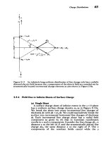
Figure
8-28
The
transverse
electric
and
magnetic
field
lines
for
the TM,I
and
TM
2 1
modes.
The
electric
field
purely
z
directed
where
the
field
lines
converge.
+
+ +
+
The
Rectangular
Waveguide
637
Again
this
equation
is
solved
by
assuming
a
product
solution
and separating
to
yield
a
solution
of
the
same
form
as
(11):
Hz(x,
y)
=
(A,
sin
k/x
+ A
2
cos
khx)(B,
sin
ky
+ B
2
cos
ky)
(28)
The
boundary
conditions
of
zero
normal components
of
H
at
the
waveguide
walls
require
that
H,(x
=
0,
y)=
0,
,(x
=
a,
y)=
0
(29)
H,(x,
Y
=
0)=
0,
H,(x,
y =
b)=
0
Using
identical
operations
as
in
(15)-(20)
for the
TM
modes
the
magnetic
field
solutions
are
jkk-Ho
mrr
nir
.
=
-
sin
k
kcos
kAy,
kx
-m,
k,
k
+k,
a
b
1k2+=kkHoossin
(30)
,
=
k
cos
kx
sin
ky
kx
+
ky
H.
=
Ho
cos
k,,
cos
k,y
The
electric
field
is
then
most
easily
obtained
from
Ampere's
law
in (1),
-1
E=-
Vx×i
(31)
]we
to
yield
j)
(ay
az
S
k,k
2
Ho
jwe(k
+k
)
cos
kx
sin
k,y
k-
,
Ho
cos
kx
sin
k,y
,= 1-/
H
(32)
kk'Ho
jowiik.2+
=
-i-•
Ho
sin
kxx
cos
ky
k.
+k•
=0
We
see
in
(32)
that
as
required
the
tangential
components
of
the
electric
field
at
the
waveguide
walls
are
zero.
The
638
Guided
Electromagnetic
Waves
surface
charge
densities
on
each
of
the
walls
are:
-~
Ho
l(x=
0,y) =
=(x
=,
y)=
(
sin
ky
(x
=
a,
y)=
-e(x
=
a,
y)=
kYH
cos
mvr
sin
ky
iwj(k,
+
hk,)
k
2
H)
.
(33)
Ck2Ho
'&(x,
y
=
0)
=
,(x,
y
=
0)
=
k
sin
k
jo(k.
+
k,)
k.k
2Ho
'(x,
y
= b)=
-e4,(x,
y=
b)=
(k
+)
cos
nr
sin
kAx
For
TE
modes,
the
surface
currents determined
from
the
discontinuity
of
tangential
H
now
flow
in
closed
paths
on
the
waveguide
walls:
K(x
=
0,
y) =
i,
x
(x
=
0,
y)
=
iH,t(x
=
0,
y)-
i,H,(x
=
0,
y)
K(x
=
a,y)
=
-i,X
i(x
=
a,
y)
=
-iH,(x
=
a,
y)+i,H
,(x
=
a,
y)
(34)
iK(x,
y =
0)
i,
x
I~(x,
y
=
0)
=
-i'/.(x,
y
=
0)
+
i/,(x,
y
=
0)
K(x,
y
=
b)
=
-i,x
l(x,
y
=
b)
=
it/,(x,
y
=
b)
-
i•.,(x,
y
=
b)
Note
that for
TE
modes
either
n
or
m
(but
not
both)
can
be
zero
and
still
yield
a
nontrivial
set
of
solutions.
As
shown
in
Figure
8-29,
when
n
is
zero
there
is
no
variation
in
the
fields
in
the
y
direction
and
the
electric
field
is
purely
y
directed
while
the
magnetic
field
has
no
y
component.
The
TE
1
l
and
TE
2 1
field
patterns
are
representative
of
the
higher
order
modes.
8-6-4
Cut-Off
The
transverse
wavenumbers
are
m•"
nlr
k,
k,=
(35)
so
that
the
axial
variation
of
the
fields
is
obtained
from
(10)
as
k,,=
[!-
-
22
(36)k2
oe,_)
V
j1~
-
4
+
+
sin
k,y
cos
k,y
.
2
z=
211
=
c
ky
k,y
,
Figure
8-29
where
the
field
,
lines
converge.
for
the
TEIo
mode.
Y
____ ___
4
-
-E
+ +
+ + +
a
TE,,
Electric
field
(-)
E,=
2
Ho
cos
kx
k•
+k
k
E2,
-=
Ho
sin
kx
kA
+k,
k
=
-
,
~
a
b
dy
E,
-ktan
kA
dx
E,
k,
tan
k,y
=>cos
k,x
cos
k,y
=
const
Magnetic
field
( - - -)
jkkHo
/
-=
sin
kx
cos
H,
~
2
cos
kx
sin
k2
+
ky
4,
=
Ho
cos
k,,x
cos
k,y
dy
H,
k,
cot
kx
dx
H,
k,
cot
k,y
[sin
kxx](
h' '
,I
) _
const
I
e1
I
E21
sin
k,y
(a)
The
transverse
electric
and
magnetic
field
lines
for
various
TE
modes.
The
magnetic
field
is
purely
z
directed
The
TE
0
o
mode
is
called
the
dominant
mode
since
it
has
the
lowest
cut-off
frequency.
(b)
Surface
current
lines
640
Guided
Electromagnetic
Waves
a-
x
4
2
4
(b)
Figure
8-29
Thus,
although
Ak
and
k,
are
real,
k
can
be
either
pure
real
or
pure
imaginary.
A
real
value
of
k.
represents
power
flow
down
the
waveguide
in
the
z
direction.
An
imaginary
value
of
k,
means
exponential
decay with
no
time-average
power
flow.
The
transition
from
propagating
waves
(kh
real)
to
evanes-
cence
(k,
imaginary)
occurs
for
k,
=
0.
The
frequency
when
k,
is
zero
is
called
the
cut-off
frequency
w,:
&= [(=C )
2
+ (nI)2]1/2
(37)
This
frequency
varies
for
each
mode
with
the
mode
parameters
m
and
n.
If
we
assume
that
a
is
greater
than
b,
the
lowest
cut-off
frequency
occurs
for
the
TE
1 0
mode,
which
is
called
the
dominant or
fundamental
mode.
No
modes
can
propagate
below
this
lowest
critical
frequency
woo:
TC
c0
o
=
-
~f
=
Hz
(38)
a
21r
2a
If
an
air-filled
waveguide
has
a
=
1
cm,
then
fro=
1.5xl0'
0
Hz,
while
if
a=10m,
then
f~o=15MHz.
This
explains
why
we
usually
cannot
hear
the
radio
when
driving
through
a
tunnel.
As
the
frequency
is
raised
above
oco,
further
modes
can
propagate.
-
3- -
.
I
I
IX_ 3_•
W
X
UX
The
Rectangular
Waveguide
641
The
phase
and
group
velocity
of
the
waves
are
VP
k
MW
2
(2
(n
.)2]
1/2
do
k'c
2
2
C
2
(39)
Vg
=
-
v=
g
y
=
C
2
dk,
w
vp
At cut-off,
v,=0
and
vp
=
o
with
their
product
always
a
constant.
8-6-5
Waveguide
Power
Flow
The
time-averaged
power
flow
per unit
area
through
the
waveguide
is
found
from the
Poynting
vector:
<S
>
=
2
Re
(E
x
HI*) (40)
(a)
Power
Flow
for
the
TM
Modes
Substituting
the
field
solutions
found
in
Section
8-6-2
into
(40)
yields
<S>
=
Re
[(xi
+
i,+
!i)
e-ik
x
(/-*iý
+*
i)
)e
+i
"
]
=
I
Re
[(EI,,/
- E4Hi'
)i.
+
E(
i
-/4
i,)]
ei
'
kk
(41)
where
we
remember
that
k.
may
be
imaginary
for
a
particular
mode
if
the
frequency
is
below
cut-off.
For
propagating
modes
where
k,
is
real
so
that
k,
=
k*,
there
is
no
z
dependence
in
(41).
For
evanescent
modes
where
k,
is
pure
imaginary,
the
z
dependence
of
the Poynting
vector
is
a
real
decaying
exponential
of
the
form
e
-21'
k".
For
either
case
we
see
from
(13)
and
(22)
that
the
product
of
E,
with
fHx
and
H,
is
pure
imaginary
so
that
the
real
parts
of
the
x-
and
y-directed time
average
power
flow
are
zero
in
(41).
Only
the
z-directed
power
flow
can
have
a
time average:
<S>=
Eo,
2
COS2
kýX
2
k'Y
<S>
=
|2 2)
Re
[k,
e-itk
-k*)(k
cos
2
kX
sin
2
k,y
2(kx
+k,
)
+kY
sin
2
kx
cos
2
kyy)]i.
(42)
If
k,
is
imaginary,
we
have
that
<S
>
=
0
while
a
real
k,
results
in
a
nonzero
time-average
power
flow.
The
total
z-directed
642
Guided
Electromagnetic
Waves
power
flow
is
found
by
integrating
(42)
over
the
cross-
sectional
area
of
the
waveguide:
<P>=
<S,>
dxdy
oekoabE(
8(k+k)
(43)
where
it
is
assumed
that
k,
is
real,
and
we
used
the
following
identities:
a
i
2
mrx
a 1I
mrx
1 .
2mrx~
I
a
m
\2
a
4
an
l
0
=
a/2,
m#O
a
0
=(44)
Cos
dx
=
-(
+-
sin
[-
a
mor
2
a
4
a o
a/2,
m#O
a,
m=0
For
the
TM
modes,
both
m
and
n
must
be
nonzero.
(b)
Power
Flow
for
the
TE
Modes
The
same
reasoning
is
used
for
the
electromagnetic
fields
found
in
Section
8-6-3
substituted
into (40):
<S
> =
Re
[(ix
+
yi,)
eik
x (•
i
x
+
i,+
fli.)
e+ikz
-
2
Re
[(•/-
-
E,/-H^*)i•
-Hz/
(Ei -
Eyi)]
e(k
-
)z
(45)
Similarly,
again
we
have
that
the
product
of
H*
with
E,
and
E,
is
pure
imaginary
so
that
there
are
no
x-
and
y-directed
time
average
power
flows.
The
z-directed power
flow
reduces
to
<S,>=
(•'
,
(k
cos
2
kx
sin'
k,y
+k'
sin
2
k,
cos
2
ky)
Re
(k,
e
-
i
(
' - k*
•)
(46)
Again
we
have
nonzero
z-directed time
average
power
flow
only
if kR
is
real.
Then
the
total
z-directed
power
is
sk
abH(2
+
k2,
m,
n
0
x
abHE
(47)
,
morn=0
(hk+ k )
The
Rectangular
Waveguide
643
where
we
again
used the identities
of
(44).
Note
the
factor
of
2
differences
in
(47)
for
either
the
TE
1
o
or
TEo,
modes.
Both
m
and
n
cannot
be zero
as
the
TE
0
o
mode
reduces
to
the
trivial
spatially
constant
uncoupled
z-directed
magnetic
field.
8-6-6
Wall
Losses
If
the
waveguide
walls
have
a
high
but
noninfinite
Ohmic
conductivity
a-,,
we
can
calculate
the
spatial
attenuation
rate
using
the
approximate
perturbation
approach
described
in
Section
8-3-4b.
The
fields
decay
as
e
- ',
where
1
<P
>
a=
I
(48)
2
<P>
where
<PaL>
is
the
time-average
dissipated
power
per
unit
length
and
<P>
is
the
electromagnetic
power
flow
in
the
lossless
waveguide
derived
in
Section
8-6-5
for
each
of
the
modes.
In
particular,
we
calculate
a
for
the
TE
0
o
mode
(k.
=
ir/a,
ky
=
0).
The
waveguide
fields
are then
(jka
s=
Hao
sin
+cos
-ai
i
a
a
E=-
-
a
Ho
sin
i
(49)
Ta
The
surface
current
on
each
wall
is
found
from
(34)
as
il(x
=
0,
y)=
kl(x
=
a,
y)=
-Hoi,
&TjkIa
(50)
i(x,
y=0)=-K(x,y=
b)=
Ho
-iL-sin-+i.cos1)-
With
lossy
walls
the
electric
field
component
E,
within
the
walls
is
in
the
same
direction
as
the
surface
current
propor-
tional
by
a
surface
conductivity
o•8,
where
8
is
the
skin
depth
as
found
in
Section
8-3-4b.
The
time-average
dissipated
power
density
per
unit
area
in
the
walls
is
then:
<Pa(x
= 0,
y)>
=
<Pd(x
=
a,
y)>
-12
Re(Ew.*)I
Ho
2
oa8
(51)
<Pd(x,
y
=
0)>
=
<Pd(x,
y
=
b)>
1
H•
k•
2
.
2
21rX
2
]
=-
_-
)
smin-
+cos21
2
o,,,8
,ir
a
a
The
total
time
average
dissipated
power
per
unit
length
<PdL>
required
in
(48)
is
obtained
by
integrating
each
of
the
644
Guided
Electromagnetic
Waves
terms
in
(51)
along
the
waveguide
walls:
<Pa>=
[<Pd(x=O,y)>+<Pd(x
=
a,y)>]
dy
+
[<P(x,y=0)>+<Pd(x,y=
b)>]
dx
Hob
Ho
k_
2
.
sin
=
+
2x
,8s
2[ir)
j
,8
2
2
C
2
while
the
electromagnetic
power
above cut-off
for
the
TElo
mode
is
given
by (47),
Iphk,abHo
<P>
=
4(r/a)
(53)
4(7r/a)2
so
that
S<Pa>
2
2C2
a
-
(54)
2
<P>
wjoabk,So8
where
k=
-
/;
->-
a
(55)
8-7
DIELECTRIC
WAVEGUIDE
We
found
in
Section
7-10-6
for
fiber optics
that
elec-
tromagnetic
waves
can
also
be
guided
by
dielectric
structures
if
the
wave
travels
from the
dielectric to
free
space
at
an
angle
of
incidence
greater
than
the
critical
angle.
Waves
prop-
agating
along
the
dielectric
of
thickness
2d
in
Figure
8-30
are
still
described
by
the
vector
wave
equations derived
in
Section
8-6-1.
8-7-1
TM
Solutions
We
wish
to
find
solutions
where
the
fields
are
essentially
confined
within
the
dielectric.
We
neglect
variations
with
y
so
that
for
TM
waves
propagating
in
the
z
direction
the
z
component
of
electric
field
is
given
in
Section
8-6-2 as
Re
[A
2
e
-
a(x - d)
e
j(It-kz)],
x-d
E,(x,t)=
Re
[(Al
sin
k~+B
cos
k,x)
eijt-k-],
IxI
ld (1)
[Re
[As
e~(x+d)
ej(Wt-kz)],
x5
-d
1