nuclear power plant design and seismic safety considerations
Bạn đang xem bản rút gọn của tài liệu. Xem và tải ngay bản đầy đủ của tài liệu tại đây (2.73 MB, 42 trang )
CRS Report for Congress
Prepared for Members and Committees of Congress
Nuclear Power Plant Design and Seismic
Safety Considerations
Anthony Andrews
Specialist in Energy and Defense Policy
Peter Folger
Specialist in Energy and Natural Resources Policy
January 12, 2012
Congressional Research Service
7-5700
www.crs.gov
R41805
Nuclear Power Plant Design and Seismic Safety Considerations
Congressional Research Service
Summary
The earthquake and subsequent tsunami that devastated Japan’s Fukushima Daiichi nuclear power
station and the earthquake that forced the North Anna, VA, nuclear power plant’s temporary
shutdown have focused attention on the seismic criteria applied to siting and designing
commercial nuclear power plants. Some Members of Congress have questioned whether U.S
nuclear plants are more vulnerable to seismic threats than previously assessed, particularly given
the Nuclear Regulatory Commission’s (NRC’s) ongoing reassessment of seismic risks at certain
plant sites.
The design and operation of commercial nuclear power plants operating in the United States vary
considerably because most were custom-designed and custom-built. Boiling water reactors
(BWRs) directly generate steam inside the reactor vessel. Pressurized water reactors (PWRs) use
heat exchangers to convert the heat generated by the reactor core into steam outside of the reactor
vessel. U.S. utilities currently operate 104 nuclear power reactors at 65 sites in 31 states; 69 are
PWR designs and the 35 are BWR designs.
One of the most severe operating conditions a reactor may face is a loss of coolant accident
(LOCA), which can lead to a reactor core meltdown. The emergency core cooling system (ECCS)
provides core cooling to minimize fuel damage by injecting large amounts of cool water
containing boron (borated water slows the fission process) into the reactor coolant system
following a pipe rupture or other water loss. The ECCS must be sized to provide adequate make-
up water to compensate for a break of the largest diameter pipe in the primary system (i.e., the so-
called “double-ended guillotine break” (DEGB)). The NRC considers the DEGB to be an
extremely unlikely event; however, even unlikely events can occur, as the magnitude 9.0
earthquake and resulting tsunami that struck Fukushima Daiichi proves.
U.S. nuclear power plants designed in the 1960s and 1970s used a deterministic statistical
approach to addressing the risk of damage from shaking caused by a large earthquake (termed
Deterministic Seismic Hazard Analysis, or DSHA). Since then, engineers have adopted a more
comprehensive approach to design known as Probabilistic Seismic Hazard Analysis (PSHA).
PSHA estimates the likelihood that various levels of ground motion will be exceeded at a given
location in a given future time period. New nuclear plant designs will apply PSHA.
In 2008, the U.S Geological Survey (USGS) updated the National Seismic Hazard Maps (NSHM)
that were last revised in 2002. USGS notes that the 2008 hazard maps differ significantly from
the 2002 maps in many parts of the United States, and generally show 10%-15% reductions in
spectral and peak ground acceleration across much of the Central and Eastern United States
(CEUS), and about 10% reductions for spectral and peak horizontal ground acceleration in the
Western United States (WUS). Spectral acceleration refers to ground motion over a range, or
spectra, of frequencies. Seismic hazards are greatest in the WUS, particularly in California,
Oregon, and Washington, as well as Alaska and Hawaii.
In 2010, the NRC examined the implications of the updated NSHM for nuclear power plants
operating in the CEUS, and concluded that NSHM data suggest that the probability for
earthquake ground motions may be above the seismic design basis for some nuclear plants in the
CEUS. In late March 2011, NRC announced that it had identified 27 nuclear reactors operating in
the CEUS that would receive priority earthquake safety reviews.
Nuclear Power Plant Design and Seismic Safety Considerations
Congressional Research Service
Contents
Background 1
Nuclear Power Plant Designs 5
Boiling Water Reactor (BWR) Systems 5
BWR Safe Shutdown Condition 6
Loss of Coolant Accident 7
BWR Design Evolution 7
Pressurized Water Reactor Systems 11
PWR Design Evolutions 12
PWR Safe Shutdown Condition 12
Loss of Coolant Accident 12
Containment Structure Designs 13
Seismic Siting Criteria 16
Safe Shutdown Earthquake Condition 16
Cumulative Absolute Velocity 17
Seismic Design Varies by Region 18
Deterministic Seismic Hazard Analysis 18
Probabilistic Seismic Hazard Analysis 19
Design Response Spectra for Seismic Design of Nuclear Power Plants 21
National Seismic Hazard Maps 22
NRC Review—Implications of Updated Probabilistic Seismic Hazard Estimates in
Central and Eastern United States on Existing Plants 28
Recent Legislative Activities 29
Policy Considerations for Monitoring Earthquakes in the CEUS in Support of Seismic
Assessments of Nuclear Power Plants 31
Figures
Figure 1. Commercial Nuclear Power Plants Operating in the United States 3
Figure 2. Boiling Water Reactor (BWR) Plant 6
Figure 3. GE BWR / Mark I Containment Structure 9
Figure 4. General Electric Mark II Containment Structure 9
Figure 5. General Electric Mark III Containment Structure 10
Figure 6. Pressurized Water Reactor (PWR) Plant 11
Figure 7. Constructing Site-Specific Ground Motion Response Spectrum 20
Figure 8. NRC Site Seismic Design Response Spectra 21
Figure 9. Operating Nuclear Power Plant Sites vs. Seismic Hazard 24
Figure 10. Operating Nuclear Power Plants vs. Seismic Hazard 25
Figure 11. Operating Nuclear Power Plant Sites and Mapped Quaternary Faults 26
Figure B-1. Seismic Zone Map of the United States 36
Nuclear Power Plant Design and Seismic Safety Considerations
Congressional Research Service
Tables
Table 1. Reactor Type, Vendor, and Containment 5
Table 2. BWR Design Evolution 8
Table 3. PWR Design Configurations 12
Table 4. Containment Building Design Parameters 15
Table 5. Operating Nuclear Power Plants Subject to Earthquake Safety Reviews 29
Appendixes
Appendix A. Magnitude, Intensity, and Seismic Spectrum 33
Appendix B. Early Seismic Zone Map 35
Appendix C. Terms 37
Contacts
Author Contact Information 37
Acknowledgments 37
Nuclear Power Plant Design and Seismic Safety Considerations
Congressional Research Service 1
Background
The seismic design criteria applied to siting commercial nuclear power plants operating in the
United States received increased attention following the March 11, 2011, earthquake and tsunami
that devastated Japan’s Fukushima Daiichi nuclear power station. Since the event, a magnitude
5.8 earthquake near Mineral, VA, on August 23, 2011, precipitated the temporary shutdown of
Dominion Power’s North Anna nuclear power plant. Some Members of Congress have
questioned whether U.S nuclear plants are more vulnerable to seismic threats than previously
assessed, particularly given the Nuclear Regulatory Commission’s (NRC’s) ongoing reassessment
of seismic risks at certain plant sites.
1
Currently, 104 commercial nuclear power plants operating in the United States use variations in
light water reactor designs and construction. Figure 1 shows the locations of all 104 nuclear
power reactors operating in the United States.
Light water reactors use ordinary water as a neutron moderator and coolant, and uranium fuel
enriched in fissile uranium-235.
2
Designs fall into either pressurized water reactor (PWR) or
boiling water reactor (BWR) categories. Both have reactor cores (the source of heat) consisting of
arrays of uranium fuel bundles capable of sustaining a controlled nuclear chain reaction.
3
U.S.
commercial nuclear power plants incorporate safety features intended to ensure that, in the event
of an earthquake, the reactor core would remain cooled, the reactor containment would remain
intact, and radioactive releases would not occur from spent fuel storage pools. NRC defines this
as the “safe-shutdown condition.”
When utilities began building nuclear power plants in the 1960s-1970s era, they typically hired an
architect/engineering firm, then contracted with a reactor manufacturer (“nuclear vendors”) to
build the nuclear steam supply system (NSSS), consisting of the nuclear core, reactor vessel,
steam generators and pressurizer (in PWRs), and control mechanisms—representing about 10%
of the plant investment.
4
The balance of the plant (BOP) consisted of secondary cooling systems,
feed-water systems, steam systems, control room, and generator systems. At the time, the four
vendors who offered designs for nuclear reactor systems in the United States were Babcock &
Wilcox, Combustion Engineering, General Electric, and Westinghouse. About 12
architect/engineering firms were available to design the balance of the plant. Each
architect/engineer had its own preferred approach to designing the balance of plant systems. The
custom design-and-build industry approach resulted in problems verifying the safety of individual
plants and in transferring the safety lessons learned from one reactor to another. In addition to the
custom-design features of each plant, designers also had to contend with earthquake hazards
unique to each plant site. Designs for structures, systems, and components important to a nuclear
power plant operation must withstand earthquakes without losing their intended safety-related
function.
1
This report does not discuss the risk from earthquake-caused tsunamis, as associated with the catastrophic damage to
the Fukushima plants.
2
Heavy water reactors, such as Canada’s CANDU reactor, use water containing a heavier hydrogen isotope and natural
uranium for fuel, which contains about 0.7% uranium-235.
3
For further background uranium fuel, see CRS Report RL34234, Managing the Nuclear Fuel Cycle: Policy
Implications of Expanding Global Access to Nuclear Power, coordinated by Mary Beth Nikitin.
4
Office of Technology Assessment, Nuclear Power Plant Standardization: Light Water Reactors, NTIS order #PB81-
213589, April 1981, p. 11.
Nuclear Power Plant Design and Seismic Safety Considerations
Congressional Research Service 2
This report presents some of the general design concepts of operating nuclear power plants in
order to discuss design considerations for seismic events. This report does not attempt to
conclude whether one design is inherently safer or less safe than another plant. Nor does it
attempt to conclude whether operating nuclear power plants are at any greater or lesser risk from
earthquakes given recent updates to seismic data and seismic hazard maps.
CRS-3
Figure 1. Commercial Nuclear Power Plants Operating in the United States
(One hundred and four [104] Operating Reactors)
Source: Prepared by the Library of Congress Geography and Maps Division for CRS using U.S. NRC Find Operating Nuclear Reactors by Location or Name,
Notes: Currently, 104 nuclear power reactors operate at 65 sites in 31 states; 69 are PWR designs and the 35 remaining are BWR designs.
CRS-4
Notes:
Unit Type MW Vendor St. Lic. Unit Type MW Vendor St. Lic. Unit Type MW Vendor St. Lic.
Arkansas Nuclear 1 PWR 843 B&W AK 1974 Grand Gulf 1 BWR 1,297 GET6 MS 1984 Point Beach 1 PWR 512 W2L WI 1970
Arkansas Nuclear 2 PWR 995 CE AK 1974 Hatch 1 BWR 876 GET4 GA 1974 Point Beach 2 PWR 514 W2L WI 1973
Beaver Valley 1 PWR 892 W3L PA 1976 Hatch 2 BWR 883 GET4 GA 1978 Prairie Island 1 PWR 551 W2L MN 1874
Beaver Valley 2 PWR 846 W3L PA 1987 Robinson 2 PWR 710 W3L SC 1970 Prairie Island 2 PWR 545 W2L MN 1974
Braidwood 1 PWR 1,178 W4L IL 1987 Hope Creek 1 BWR 1,061 GET4 NJ 1986 Quad Cities 1 BWR 867 GET3 IL 1972
Braidwood 2 PWR 1,152 W4L IL 1988 Indian Point 2 PWR 1,023 W4L NY 1973 Quad Cities 2 BWR 869 GET3 IL 1972
Browns Ferry 1 BWR 1,065 GET4 AL 1973 Indian Point 3 PWR 1,025 W4L NY 1975 R. E. Ginna PWR 498 W2L NY 1969
Browns Ferry 2 BWR 1,104 GET4 AL 1974 Joseph M. Farley 1 PWR 851 W3L AL 1977 River Bend 1 BWR 989 GET6 LA 1985
Browns Ferry 3 BWR 1,115 GET4 AL 1976 Joseph M. Farley 2 PWR 860 W3L AL 1981 Salem 1 PWR 1,174 W4L NJ 1976
Brunswick 1 BWR 938 GET4 NC 1976 Kewaunee PWR 556 W2L WI 1973 Salem 2 PWR 1,130 W4l NJ 1981
Brunswick 2 BWR 937 GET4 NC 1974 LaSalle County 1 BWR 1,118 GET5 IL 1982 San Onofre 2 PWR 1,070 CE CA 1982
Byron 1 PWR 1,164 W4L IL 1985 LaSalle County 2 BWR 1,120 GET5 IL 1983 San Onofre 3 PWR 1,080 CE CA 1992
Byron 2 PWR 1,136 W4L IL 1987 Limerick 1 BWR 1,134 GET4 PA 1985 Seabrook 1 PWR 1,295 W4L NH 1990
Callaway 1 PWR 1,236 WFL MO 1984 Limerick 2 BWR 1,134 GET4 PA 1989 Sequoyah 1 PWR 1,148 W4L TN 1980
Calvert Cliffs 1 PWR 873 CE MD 1974 McGuire 1 PWR 1,100 W4L NC 1981 Sequoyah 2 PWR 1,126 W4L TN 1981
Calvert Cliffs 2 PWR 862 CE MD 1976 McGuire 2 PWR 1,100 W4L NC 1983 Shearon Harris 1 PWR 900 W3L NC 1986
Catawba 1 PWR 1,129 W4L SC 1985 Millstone 2 PWR 884 CE CT 1975 South Texas 1 PWR 1,410 W4L TX 1988
Catawba 2 PWR 1,129 W4L SC 1986 Millstone 3 PWR 1,227 W4L CT 1986 South Texas 2 PWR 1,410 W4L TX 1989
Clinton 1 BWR 1,065 GET6 IL 1987 Monticello BWR 579 GET3 MN 1970 St. Lucie 1 PWR 839 CE FL 1976
Columbia Gen. St. BWR 1,190 GET5 WA 1984 Nine Mile Pt .1 BWR 621 GET2 NY 1974 St. Lucie 2 PWR 839 CE FL 1983
Comanche Peak 1 PWR 1,200 W4L TX 1990 Nine Mile Pt. 2 BWR 1,140 GET5 NY 1987 Surry 1 PWR 799 W3L VA 1972
Comanche Peak 2 PWR 1,150 W4L TX 1993 North Anna 1 PWR 981 W3L VA 1978 Surry 2 PWR 799 W3l VA 1973
Cooper Station BWR 830 GET4 NE 1974 North Anna 2 PWR 973 W3L VA 1980 Susquehanna 1 BWR 1,149 GET4 PA 1982
Crystal River 3 PWR 838 B&WLL FL 1976 Oconee 1 PWR 846 B&WLL SC 1973 Susquehanna 2 BWR 1,140 GET4 PA 1984
Davis-Besse PWR 893 B&WLL OH 1977 Oconee 2 PWR 846 B&WLL SC 1973 Three Mile Isl. 1 PWR 786 B&WLL PA 1974
Diablo Canyon 1 PWR 1,151 W4L CA 1984 Oconee 3 PWR 846 B&WLL SC 1974 Turkey Point 3 PWR 720 W3L FL 1972
Diablo Canyon 2 PWR 1149 W4L CA 1985 Oyster Creek BWR 619 GET2 NJ 1991 Turkey Point 4 PWR 720 W3l FL 1973
Donald C. Cook 1 PWR 1,009 W4L MI 1974 Palisades PWR 778 CE MI 1971 VC Summer PWR 966 W3l SC 1982
Donald C. Cook 2 PWR 1,060 W4L MI 1977 Palo Verde 1 PWR 1,335 CES80 AZ 1985 Vermont Yankee BWR 510 GET4 VT 1972
Dresden 2 BWR 867 GET3 IL 1991 Palo Verde 2 PWR 1,335 CES80 AZ 1986 Vogtle 1 PWR 1,109 W4L GA 1987
Dresden 3 BWR 867 GET3 IL 1971 Palo Verde 3 PWR 1,335 CES80 AZ 1987 Vogtle 2 PWR 1,127 W4L GA 1989
Duane Arnold BWR 640 GET4 IA 1974 Peach Bottom 2 BWR 1,112 GET4 PA 1973 Waterford 3 PWR 1,250 CE LA 1985
Fermi 2 BWR 1,122 GET4 MI 1985 Peach Bottom 3 BWR 1,112 GET4 PA 1974 Watts Bar 1 PWR 1,123 W4l TN 1996
Fitzpatrick BWR 852 GET4 NY 1974 Perry 1 BWR 1,261 GET6 OH 1986 Wolf Creek 1 PWR 1,166 W4L KS 1985
Fort Calhoun PWR 500 CE NE 1973 Pilgrim 1 BWR 685 GET3 MA 1972
Notes: No commercial nuclear power plants operate in Alaska or Hawaii. B&W: Babcock & Wilcox 2-Loop Lower; CE: Combustion Engineering; CE80: Combustion
Engineering System 80; W2L Westinghouse 2-Loop; W3L Westinghouse 3-Loop; W4L Westinghouse 4-Loop; GET2: General Electric Type 2; GET3: General Electric
Type 3; GET4: General Electric Type 4; GET5: General Electric Type 5; GET6: General Electric Type 6.
Nuclear Power Plant Design and Seismic Safety Considerations
Congressional Research Service 5
Nuclear Power Plant Designs
General design criteria for nuclear power plants require that structures and components important
to safety withstand the effects of earthquakes, tornados, hurricanes, floods, tsunamis, and seiche
waves
5
without losing the capability to perform their safety function. These “safety-related”
structures, systems, and components are those necessary to assure:
• The capability to maintain the reactor coolant pressure,
• The capability to shut down the reactor and maintain it in a safe condition, or
• The capability to prevent or mitigate the consequences of accidents, which could
result in potential offsite radiation exposures.
All BWR plants operating in the United States use variations of a General Electric design. The
more numerous PWR plants use Babcock & Wilcox, Combustion Engineering, and Westinghouse
designs. Table 1 summarizes the various reactor types. The sections that follow discuss them
further.
Table 1. Reactor Type, Vendor, and Containment
Type Vendor Containment No. of operating reactors.
BWR General Electric Type 2 Wet, Mark I 2
General Electric Type 3 Wet, Mark I 6
General Electric Type 4 Wet, Mark 1 15
General Electric Type 4 Wet, Mark II 4
General Electric Type 5 Wet, Mark II 4
General Electric Type 6 Wet, Mark III 4
35
PWR Babcock & Wilcox 2-Loop Lower Dry, Ambient Pressure 7
Combustion Engineering Dry, Ambient Pressure 11
Combustion Engineering System 80 Large Dry, Ambient Pressure 3
Westinghouse 2-Loop Dry, Ambient Pressure 6
Westinghouse 3-Loop Dry, Ambient Pressure 7
Westinghouse 3-Loop Dry, Sub-atmospheric 6
Westinghouse 4-Loop Dry, Ambient Pressure 18
Westinghouse 4-Loop Dry, Sub-atmospheric 1
Westinghouse 4-Loop Wet, Ice Condenser 9
Westinghouse 4-Loop Dry, Ambient Pressure 1
69
Source: U.S. NRC.
Boiling Water Reactor (BWR) Systems
A boiling water reactor generates steam directly inside the reactor vessel as water flows upward
through the reactor’s core (see Figure 2).
6
The water also cools the reactor core, and the reactor
5
Standing waves, or waves that move vertically but not horizontally. Seiche waves can be triggered by earthquakes,
strong winds, tides, and other causes.
6
U.S. Nuclear Regulatory Commission, Reactor Concepts Manual, Boiling Water Reactor Systems,
(continued )
Nuclear Power Plant Design and Seismic Safety Considerations
Congressional Research Service 6
operator is able to vary the reactor’s power by controlling the rate of water flow through the core
with recirculation pumps and jet pumps. The generated steam flows out the top of the reactor
vessel through pipelines to a combined high-pressure/low-pressure turbine-generator. After the
exhausted steam leaves the low-pressure turbine, it runs through a condenser/heat exchanger that
cools the steam and condenses it back to water. A series of pumps return the condensed water
back to the reactor vessel. The heat exchanger cycles cooling water through a cooling tower, or
takes in water and directly discharges it to a lake, river, or ocean. The water that flows through the
reactor, steam turbines, and condenser is a closed loop that never contacts the outside
environment under normal operating conditions. Reactors of this design operate at temperatures
of approximately 570º F and pressures of 1,000 pounds per square inch (psi) atmospheric.
Figure 2. Boiling Water Reactor (BWR) Plant
(Generic Design Features)
Source: U.S. Nuclear Regulatory Commission, Reactor Concepts Manual, Boiling Water Reactor Systems, 2005.
BWR Safe Shutdown Condition
In the case of events that cause a nuclear power plant to exceed its operating parameters (for
example, an earthquake or a critical component’s failure) design safety features must provide a
means to control reactivity and cool the reactor.
During normal operation, reactor cooling relies on the water that enters the reactor vessel and the
generated steam that exits. During safe shutdown, after the fission process is halted, the reactor
( continued)
October 17, 2005.
Nuclear Power Plant Design and Seismic Safety Considerations
Congressional Research Service 7
core continues to generate heat by radioactive decay and generates steam.
7
The heat from this
radioactive decay initially equals about 6% of the heat produced by the reactor at full power and
gradually declines. Under this condition, the steam bypasses the turbine and diverts directly to the
condenser to cool the reactor. When the reactor vessel pressure decreases to approximately 50 psi,
the shutdown-cooling mode removes residual heat by pumping water from the reactor
recirculation loop through a heat exchanger and back to the reactor via the recirculation loop. The
recirculation loop design limits the number of pipes that penetrate the reactor vessel.
Loss of Coolant Accident
The most severe operating condition affecting a BWR is a loss of coolant accident (LOCA). In
the absence of coolant, the uncovered reactor core continues to generate heat through radioactive
decay. The resulting heat buildup can damage the fuel or fuel cladding and lead to a fuel
“meltdown.” Under such a condition, an emergency core cooling system (ECCS) provides water
to cool the reactor core. The ECCS is an independent high-pressure coolant injection system that
requires no auxiliary electrical power, plant air systems, or external cooling water systems to
provide makeup water under small and intermediate loss of coolant accidents. A low-pressure
ECCS sprays water from the suppression pool into the reactor vessel and on top of the fuel
assemblies.
8
The ECCS must also be sized to provide adequate makeup water to compensate for a
break of the largest diameter pipe in the primary system (i.e., the so-called “double-ended
guillotine break” (DEGB)). The NRC views the DEGB as an extremely unlikely event (likely to
occur only once per 100,000 years of reactor operation).
9
BWR Design Evolution
Only General Electric boiling water reactors operate in the United States (Table 1). BWRs are
inherently simpler designs than other light water reactor types. Since they heat water and generate
steam directly inside the reactor vessel, they have fewer components than pressurized water
reactors. The original BWR design-types have been decommissioned, but Type 2 through Type 6
BWRs continue to operate. Some of the BWR evolutionary design features are summarized in
Table 2. Along with the evolution in BWR reactor design, containment structure designs have
also evolved (Figure 3, Figure 4, and Figure 5).
7
During the sustained chain reaction in an operating reactor, the U-235 splits into highly radioactive fission products,
while the U-238 is partially converted to plutonium-239 by neutron capture, some of which also fissions. Further
neutron capture creates other radioactive elements. The process of radioactive decay transforms an atom to a more
stable element through the release of radiation—alpha particles (two protons and two neutrons), charged beta particles
(positive or negative electrons), or gamma rays (electromagnetic radiation).
8
The NRC regulates the design, construction, and operation requirements of the ECCS under 10 CFR50.46,
“Acceptance criteria for emergency core cooling systems for light-water nuclear reactors”; Appendix K to 10 CFR 50,
“ECCS Evaluation Models”; and Appendix A to 10 CFR 50, “General Design Criteria [GDC] for Nuclear Power
Plants” (e.g., GDC 35, “Emergency Core Cooling”).
9
N.C. Chokshi, S.K. Shaukat, and A.L. Hiser, et al., Seismic Considerations for the Transition Break Size, U.S.
Nuclear Regulatory Commission, NUREG 1903, Brookhaven National Laboratory, February 2008.
Nuclear Power Plant Design and Seismic Safety Considerations
Congressional Research Service 8
Table 2. BWR Design Evolution
Model
Year
Introduced Design Feature Typical Plants
BWR/1 1955 Natural circulation
First internal steam separation
Isolation condenser
Pressure Suppression Containment
Dresden 1
Big Rock Point
Humboldt Bay
BWR/2 1963 Large direct cycle Oyster Creek
BWR/3/4 1965/1966 First jet pump application
Improved Emergency Core Cooling System (ECCS); spray and
flood
Reactor Core Isolation Cooling, (RCIC) system
Dresden 2
Browns Ferry
BWR/5 1969 Improved ECCS systems
Valve recirculation flow control
LaSalle
9 Mile Point 2
BWR/6 1972 Improved jet pumps and steam separators
Reduced fuel duty: 13.4 kW/ft, 44 kW/m
Improved ECCS performance
Gravity containment flooder
Solid-state nuclear system protection system (Option, Clinton
only)
Compact control room option
Clinton
Grand Gulf
Perry
Source: M. Ragheb, Chapter 3, Boiling Water Reactors, />NPRE%20402%20ME%20405%20Nuclear%20Power%20Engineering/Boiling%20Water%20Reactors.pdf.
Note: All BWR/1 plants that operated in the United States have been decommissioned.
Nuclear Power Plant Design and Seismic Safety Considerations
Congressional Research Service 9
Figure 3. GE BWR / Mark I Containment Structure
(Showing Torus Suppression Pool)
Source: General Electric, in NRC Boiling Water Reactor (BWR) Systems, />teachers/03.pdf.
Note: Japan’s Fukushima Daiichi plants use designs similar to this.
Figure 4. General Electric Mark II Containment Structure
Source: General Electric, in NRC Boiling Water Reactor (BWR) Systems, />teachers/03.pdf.
Nuclear Power Plant Design and Seismic Safety Considerations
Congressional Research Service 10
Figure 5. General Electric Mark III Containment Structure
Source: General Electric, in NRC Boiling Water Reactor (BWR) Systems, />teachers/03.pdf.
Notes:
Reactor Building Auxiliary Building Fuel Building
1. Shield Building 16. Steam Line Channel 19. Spent Fuel Shipping cask
2. Free Standing Steel Containment 17. RHR System 20. Fuel Storage Pool
3. Upper Pool 18. Electrical Equipment Room 21. Fuel Transfer Pool
4. Refueling Platform 22. Cask Loading Pool
5. Reactor Water Cleanup 23. Cask Handling Crane
6. Reactor Vessel 24. Fuel Transfer Bridge
7. Steam Line 25. Fuel Cask Skid on Railroad Car
8. Feed-water Line
9. Recirculation Loop
10. Suppression Pool
11. Weir Wall
12. Horizontal Vent
13. Dry Well
14. Shield Wall
15. Polar Crane
Nuclear Power Plant Design and Seismic Safety Considerations
Congressional Research Service 11
Pressurized Water Reactor Systems
A pressurized water reactor (PWR) generates steam outside the reactor vessel, unlike a BWR
design. A primary system (reactor cooling system) cycles superheated water from the core to a
heat exchanger/steam generator. A secondary system then transfers steam to a combined high-
pressure/low-pressure turbine generator (Figure 6).
10
Steam exhausted from the low-pressure
turbine runs through a condenser that cools and condenses it back to water. Pumps return the
cooled water back to the steam generator for reuse. The condenser cools the steam leaving the
turbine-generator through a third system by flowing past a heat-exchanger that recycles cooling
water through a cooling tower, or takes in water and directly discharges it to a lake, river, or
ocean. Unlike a BWR design, the cooling water that flows through the reactor core never contacts
the turbine-generator. Under normal operating conditions, reactor cooling-water does not contact
the environment.
Figure 6. Pressurized Water Reactor (PWR) Plant
(Generic Design Features)
Source: U.S. Nuclear Regulatory Commission, Reactor Concepts Manual, Boiling Water Reactor Systems, 2005.
Notes: PIZ – Pressurizer; S/G – Steam Generator; RHR- Residual Heat Removal; RCP- Reactor Coolant Pump;
HTR-Heater; MSR-Moisture Separator Reheater
To keep the reactor operating under ideal conditions, a pressurizer keeps water and steam
pressure under equilibrium conditions. The pressurizer is part of the reactor coolant system, and
consists of electrical heaters, pressure sprays, power-operated relief valves, and safety valves. For
example, if pressure rises too high, water spray cools the steam in the pressurizer; or if pressure is
too low, the heaters increase steam pressure. The cause of the pressure deviation is normally
associated with a change in the temperature of the reactor coolant system.
10
U.S. NRC, Reactor Concepts Manual, Pressurized Water Reactor Systems, />teachers/04.pdf - 2005-10-17.
Nuclear Power Plant Design and Seismic Safety Considerations
Congressional Research Service 12
PWR Design Evolutions
All PWR systems consist of the same major components, but arranged and designed differently.
For example, Westinghouse has built plants with two, three, or four primary coolant loops,
depending upon the power output of the plant.
Table 3. PWR Design Configurations
Manufacturer
Steam
Generators
Reactor
Coolant
Pumps
Fuel
Assemblies Megawatts Operating
Westinghouse
Two-Loop
a
2 2 121 500 6
Three-Loop
b
3 3 157 700-900 13
Four Loop
c
4 4 193 950-1,250 29
Babcock-Wilcox
d
2 4 177 850 7
Combustion Engineering
e
2 4 500 – 1,200 14
a. The two-loop units in the United States are Ginna, Kewaunee, Point Beach 1 and 2, and Prairie Island 1 and
2.
b. The three-loop units in the United States are Beaver Valley 1 and 2, Farley 1 and 2, H. B. Robinson 2, North
Anna 1 and 2, Shearon Harris 1, V. C. Summer, Surry 1 and 2, and Turkey Point 3 and 4.
c. The four-loop units in the United States are Braidwood 1 and 2, Byron 1 and 2, Callaway, Catawba 1 and 2,
Comanche Peak 1 and 2, D. C. Cook 1 and 2, Diablo Canyon 1 and 2, Indian Point 2 and 3, McGuire 1 and
2, Millstone 3, Salem 1 and 2, Seabrook, Sequoyah 1 and 2, South Texas Project 1 and 2, Vogtle 1 and 2,
Watts Bar 1, and Wolf Creek.
d. The Babcock & Wilcox units in the United States are Arkansas 1, Crystal River 3, Davis Besse, Oconee 1, 2,
and 3, and Three Mile Island 1.
e. The Combustion Engineering units in the United States are Arkansas 2, Calvert Cliffs 1 and 2, Fort Calhoun,
Millstone 2, Palisades, Palo Verde 1, 2, and 3, San Onofre 2 and 3, Saint Lucie 1 and 2, and Waterford 3.
PWR Safe Shutdown Condition
During normal operation, a PWR does not generate steam directly. For cooling, it transfers heat
via the reactor primary coolant to a secondary coolant in the steam generators. There, the
secondary coolant water is boiled into steam and sent to the main turbine to generate electricity.
Even after shutdown (when the moderated uranium fission is halted), the reactor continues to
produce a significant amount of heat from decay of uranium fission products (decay heat). The
decay heat is sufficient to cause fuel damage if the core cooling is inadequate. Auxiliary feed-
water systems and the steam dump systems work together to remove the decay heat from the
reactor. If a system for dumping built-up steam is not available or inoperative, atmospheric relief
valves can dump the steam directly to the atmosphere. Under normal operating conditions, water
flowing through the secondary system does not contact the reactor core; dumped-steam does not
present a radiological release.
Loss of Coolant Accident
As with BWRs, the most severe operating condition affecting a PWR is the loss of coolant
accident (LOCA); the extreme case represented by the double-ended guillotine break (DEGB) of
Nuclear Power Plant Design and Seismic Safety Considerations
Congressional Research Service 13
large diameter pipe systems. In the event of a LOCA, the reactor’s emergency core cooling
system (ECCS) provides core cooling to minimize fuel damage by injecting large amounts of
cool, borated water into the reactor coolant system from a storage tank. The borated water stops
the fission process by absorbing neutrons, and thus aids in shutting down the reactor.
The ECCS on the PWR consists of four separate systems: the high-pressure injection (or
charging) system, the intermediate pressure injection system, the cold leg accumulators, and the
low-pressure injection system (residual heat removal). The high-pressure injection system
provides water to the core during emergencies in which reactor coolant-system pressure remains
relatively high (such as small breaks in the reactor coolant system, steam break accidents, and
leaks of reactor coolant through a steam generator tube to the secondary side). The intermediate
pressure injection system responds to emergency conditions under which the primary pressure
stays relatively high; for example, small to intermediate size primary breaks. The cold leg
accumulators operate without electrical power by using a pressurized nitrogen gas bubble on the
top of tanks that contain large amounts of borated water. The low-pressure injection system
removes residual heat by injecting water from the refueling water storage tank into the reactor
coolant system during large breaks (which would cause very low reactor coolant-system
pressure).
Containment Structure Designs
All U.S. reactors have primary containment structures designed to minimize releases of
radioactive material into the environment. The PWR primary containment structure must
surround all the components of the primary cooling system, including the reactor vessel, steam
generators, and pressurizer. BWR primary containments typically are smaller, because there are
no steam generators or pressurizers.
Containments must be strong enough to withstand the pressure created by large amounts of steam
that the reactor cooling system may release during an accident. The largest containment designs
provide sufficient space for steam released by an accident to expand and cool to keep pressure
within the design parameters of the structure. Smaller containments, such as those for BWRs,
require pressure suppression systems to condense much of the released steam into water. Smaller
PWR containments also may include pressure suppression systems, such as ice condensers.
11
To further limit the leakage from the containment structure following an accident, a steel liner
that covers the inside surface of the containment building acts as a vapor-proof membrane to
prevent any gas from escaping through any cracks that may develop in the concrete of the
containment structure. Two systems act to reduce temperature and pressure within the
containment structure: a fan cooler system that circulates air through heat exchangers, and a
containment spray system.
All U.S. PWR designs include a containment system with multiple Engineered Safety Features
(ESFs).
12
A dry containment system consists of a steel shell surrounded by a concrete biological
shield that protects the reactor against outside elements, for example, debris driven by hurricane
11
Kazys Almenas and R. Lee, Nuclear Engineering: An Introduction (Berlin: Springer-Verlag, 1992), pp. 507-514.
12
M. Ragheb, Containment Structures (2011). University of Illinois Champaign-Urbana, />mragheb/www/NPRE%20457%20CSE%20462%20Safety%20Analysis%20of%20Nuclear%20Reactor%20Systems/
Containment%20Structures.pdf.
Nuclear Power Plant Design and Seismic Safety Considerations
Congressional Research Service 14
winds or an aircraft strike.
13
The outer shield does not have a design function as a barrier against
the release of radiation. Although the concrete structures in existing plants act as insulators
against uncontrolled releases of radioactivity to the environment, they will fail if the ESFs fail in
their function. A summary of containment building design features appears in Table 4.
The NRC Containment Performance Working Group studied containment buildings in 1985 to
estimate their potential leak rates as a function of increasing internal pressure and temperature
associated with severe accident sequences involving significant core damage.
14
It indentified
potential leak paths through containment penetration assemblies (such as equipment hatches,
airlocks, purge and vent valves, and electrical penetrations) and their contributions to leakage
from for the containment. Because the group lacked reliable experimental data on the leakage
behavior of containment penetrations and isolation barriers at pressures beyond their design
conditions, it relied on an analytical approach to estimate the leakage behavior of components
found in specific reference plants that approximately characterize the various containment types.
13
NRC regulations require that new reactors be designed to withstand the impact of large commercial aircraft and that
existing plants develop strategies to mitigate the effects of large aircraft crashes. See CRS Report RL34331, Nuclear
Power Plant Security and Vulnerabilities, by Mark Holt and Anthony Andrews.
14
U.S. Nuclear Regulatory Commission, General Studies of Nuclear Reactors; BWR Type Reactors; Containment;
Reactor Accidents; Leaks; PWR Type Reactors; Accidents; Reactors; Water Cooled Reactors; Water Moderated
Reactors, NUREG-1037, May 1, 1985.
CRS-15
Table 4. Containment Building Design Parameters
Containment Type, plant Parameter Technical Specification
Containment capability pressure 149 psia
0
Upper bound spike pressure 107 psia
Early failure physically unreasonable best estimate pressure rise, including heat sinks 10 psi/hour
SP-1, Zion
Time to failure, best estimate with unlimited water in cavity 16 hours
Containment capability pressure 134 psia
Upper bound spike pressure 107 psia SP-2, Surry
Time to failure, early failure physically unreasonable best estimate with dry cavity Several days
Containment capability pressure 65 psia, 330 ºF
Upper bound loading pressure 70-100 psia
Lower bound loading pressure 50-70 psia
Thermal loads 500-700 ºF
SP-3, Sequoyah
Early failure Quite likely
Containment capability pressure 132 psia, 330 ºF
Upper bound loading pressure 132 psia in 40 minutes
Lower bound loading pressure 132 psia in 2 hours
Thermal loads 500-700 ºF
SP-4, Browns Ferry
Early failure Quite likely
Containment capability pressure 75 psia
Upper bound loading pressure 30 psia
Wall heat flux 1,000 to 10,000 Btu/hr-square foot
Penetration seal temperature 345 ºF
Pressurization failure from diffusion flames Unreasonable
SP-6, Grand Gulf
Seal failure Unlikely
Containment capability pressure 155 psia, 330 ºF
Upper bound loading pressure 145 psia in 2-3 hours
Lower bound loading pressure 100 psia in 3 hours
Thermal loads 500-700 ºF
SP-15, Limerick
Early failure Rather unlikely
Source: U.S. NRC, General Studies of Nuclear Reactors; BWR Type Reactors; Containment; Reactor Accidents; Leaks; PWR Type Reactors; Accidents; Reactors; Water Cooled Reactors;
Water Moderated Reactors, NUREG-1037, 1985, as cited by M. Ragheb UICU (see footnotes).
Notes: The NRC never released NUREG-1037, but draft versions apparently circulated. Psia = pounds per square inch atmospheric.
Nuclear Power Plant Design and Seismic Safety Considerations
Congressional Research Service 16
Seismic Siting Criteria
Earthquakes occur when stresses in the earth exceed the strength of a rock mass, creating a fault
or mobilizing an existing fault.
15
The fault can slip laterally (a strike/slip fault, such as the San
Andreas Fault), move vertically (a thrust or reverse fault, such as the fault that caused the March
11 Japanese earthquake), or move in some combination of the two. The fault’s sudden release
sends seismic shock waves through the earth that have two primary characteristics: (1)
amplitude—a measure of the peak wave height, and (2) period—the time interval between the
arrival of successive peaks or valleys.
16
The seismic wave’s arrival causes ground motion. The
intensity of ground motion depends primarily on three factors: the distance from the source (also
known as focus or epicenter), the amount of energy released (magnitude of the earthquake), and
the type of soil or rock at the site.
In general, for a given magnitude earthquake,
the shallower the focus, the stronger the wave
will be when reaching the surface. In addition,
the intensity of ground shaking diminishes
with increasing distance from the earthquake
focus. Sites with deep, soft soils or loosely
compacted fill will experience stronger ground
motion than sites with stiff soils or rock.
Safe Shutdown Earthquake Condition
In 1973, the concept of the “safe shutdown earthquake” (SSE) was introduced in Title 10 Part 100
of the Code of Federal Regulations (10 CFR 100), Appendix A—Seismic and Geologic Siting
Criteria for Nuclear Power Plants. The NRC defines the Safe Shutdown Earthquake as the
maximum earthquake in which certain structures, systems, and components, important to safety,
must remain functional.
17
Under an “operating basis earthquake,” the reactor could continue
operation without undue risk to the safety of the public.
Ground motion at any specific location, such as a nuclear plant site, depends on the earthquake
source, magnitude, distance to the source, and the attenuation (dampening) caused by rock and
soil characteristics. A nuclear power plant responds to an earthquake depending on how its
individual structures, systems, and components resonate, or vibrate, with the ground shaking.
Heavier and more massive structures resonate at lower frequencies, while light components
resonate at higher frequencies.
During an earthquake, ground motion transmits vibrations to a nuclear power plant’s foundation
and structure. The vibrations cause back-and-forth acceleration of a structure, system or
components that is measured relative to the earth’s gravitational acceleration constant (g). Both
15
The Applied Technology Council (ATC) and the Structural Engineers Association of California (SEAOC), Briefing
Paper 1 Building Safety and Earthquakes Part A: Earthquake Shaking and Building Response, Redwood City, CA,
16
The wave’s frequency is the inverse of the period (1/s), and is expressed as the number of wave cycles per second
(termed Hertz or Hz).
17
Earthquake Magnitude
The common measure of an earthquake’s magnitude (M)
refers to the logarithmic Richter scale, thus an M 7.0
earthquake has an amplitude that is ten times larger than
an M 6.0, but releases 31.5 times more energy than an M
6.0 earthquake.
Nuclear Power Plant Design and Seismic Safety Considerations
Congressional Research Service 17
vertical and horizontal components of ground acceleration place loads, or stresses, on a nuclear
power plant’s structure.
18
Peak Ground Acceleration (PGA) is a measure that has been widely
used in developing nuclear power plant “fragility estimates,” which represent the sensitivity of
nuclear plant structures, systems, and components (SSCs) to the inertial effects of acceleration
during ground shaking.
Cumulative Absolute Velocity
Structural damage to nuclear power plants occurs when the cumulative effects of ground
acceleration (seismically induced vibrations) cross a certain threshold. The Electric Power
Research Institute (EPRI) developed the concept of “cumulative absolute velocity” (CAV) in
1988 as an index for indicating the onset of structural damage from the cumulative effects of
ground acceleration.
19
The threshold between damaging and non-damaging earthquakes (for well-
designed buildings) conservatively occurs at ground motions with cumulative absolute velocities
(CAV) greater than 0.16 g-seconds.
20
In simple terms, CAV is the sum of various ground
acceleration frequencies (measured in terms of g) and the duration of their acceleration (measured
in seconds). An example of this phenomenon is a wire coat-hanger that breaks from metal fatigue
after being rapidly bent multiple times.
Experimental and empirical seismic data have provided insights into the behavior of different
structures under various acceleration and shaking conditions. For example, welded steel piping at
nuclear power plants rarely failed when peak ground accelerations remained below 0.5g.
21
Other
types of structures exhibit different behaviors. Engineers design the various plant structures to
withstand a certain severity of earthquake and estimates of ground shaking specific to each plant
site.
The maximum vibratory accelerations of the Safe Shutdown Earthquake must take into account
the characteristics of the underlying soil material in transmitting the earthquake-induced motions
at the various locations of the plant’s foundation. Various plant structures, depending upon their
elevation above the foundation, vibrate at different frequencies during an earthquake. Vibrations
in the range of 1 to 10 Hz are particularly problematic, because a wide range of structures are
susceptible to damaging resonance at those frequencies.
22
These accelerations and the
corresponding shaking frequencies are factors in the Probabilistic Seismic Hazard Analysis
(PSHA, discussed below). The full seismic spectrum often can be characterized by two intervals:
peak ground acceleration (PGA) and spectral acceleration (SA) averaged between 5 and 10 hertz
(Hz).
18
Gravitation acceleration g = 32 feet/second/second (ft/second
2
).
19
Kenneth W. Campbell and Yousef Bozorgnia, “A Ground Motion Prediction Equation for the Horizontal Component
of Cumulative Absolute Velocity on the PEER-NGA Strong Motion Database,” Earthquake Spectra, vol. 26, no. 3
(August 2010), p. 635.
20
Nuclear Regulatory Commission, A Performance-Based Approach to Define the Site Specific Earthquake Ground
Motion, regulatory Guide 1.208, March 2007, p. 7.
21
N.C. Chokshi, S.K. Shaukat, and A.L. Hiser, et al., Seismic Considerations for the Transition Break Size, U.S. NRC,
NUREG-1903, February 2008, pp. 29-30.
22
Frequency Hz (Hertz) refers to the number of cycles per second (which is inverse of the ground motion wave period
─ the time between two wave peaks). Thus, 0.2-s is the equivalent of 5 Hz (1/0.2-s), and 1-s is the equivalent of 1 Hz
(1/1-s).
Nuclear Power Plant Design and Seismic Safety Considerations
Congressional Research Service 18
Seismic Design Varies by Region
In the western United States (WUS), where earthquakes with frequencies below 15 Hz
predominate, earthquake magnitude is a principal design consideration for nuclear power plants.
23
Earthquakes below the 10 Hz frequency range pose the greatest hazard to nuclear power plants.
24
In the central and eastern United States (CEUS), designs considered both earthquake magnitude
and Modified Mercalli Intensity (MMI) due to sparse recordings of actual earthquake events.
25
While plants designed to operate in the CEUS must also withstand low frequency earthquakes,
the earthquakes that do occur are associated more often with higher frequencies than in the WUS.
Higher frequency earthquakes are less damaging to large structures but may adversely affect
small components.
26
Deterministic Seismic Hazard Analysis
By the late 1940s, structural engineers had begun considering the shear forces caused by
earthquakes that structures must resist. To supplement their design calculations, they referred to
the Seismic Zone Map published by the Uniform Building Code (UBC).
27
(Refer to Appendix
Figure B-1.) The UBC map divided the United State into six distinct seismic zones representing
various degrees of seismic risk. The map expressed peak ground acceleration as the decimal ratio
of the gravitational acceleration constant (g) that applied to a Maximum Credible Earthquake
(MCE) and an Operating Basis Earthquake (OBE). UBC defined a maximum credible earthquake
and its associated ground motion as the largest magnitude earthquake that could reasonably occur
along the recognized faults or within a particular seismic source. An operating basis earthquake
was defined as having the greatest level of ground motion likely to occur during the economic life
of a structure.
Designs for nuclear power plants granted construction permits during the 1960s and 1970s
applied a deterministic approach to seismic design based on site-specific investigations of local
and regional seismology, geology, and geotechnical soil conditions to determine the maximum
credible earthquake from a single source (fault).
28
Deterministic Seismic Hazard Analysis
(DSHA) attempted to quantify the effects of a maximum credible earthquake based on known
seismic sources sufficiently near the site and available historical seismic and geological data to
estimate ground motion at the plant site.
29
Appendix A to 10 CFR 100 requires an investigation of fault and earthquake occurrences to
provide the basis for determining a safe shutdown earthquake. Appendix A to 10 CFR 100 notes
23
See Appendix A for a discussion of earthquake magnitude.
24
J. Hamel, K. Huffman, and R. Kassawara, “Nuclear Seismic Safety: Modeling Risk in the Real World,” EPRI
Journal, Summer 2010, p. 15.
25
However, in the CEUS, magnitude is increasingly used as the measure of earthquake size, and ground motions are
correspondingly estimated using correlations with magnitude.
26
Hamel et al.
27
The International Building Code (IBC) published by the International Code Council (ICC) replaced the UBC in
2000.
28
U.S. Nuclear Regulatory Commission, Evaluation of the Seismic Design Criteria in ASCE/SEI Standard 43-05 for
Application to Nuclear Power Plants, NUREG/CR-6926, Brookhaven National Laboratory, NY, March 2007.
29
U.S. Army Corps of Engineers, Earthquake Design and Evaluation for Civil Works Projects (ER 1110-2-1806), July
31, 1995.
Nuclear Power Plant Design and Seismic Safety Considerations
Congressional Research Service 19
the limitations for basing seismic design criteria on literature reviews of geophysical and geologic
information, and requires supplementing the investigation with studies for vibratory ground
motion, evidence of surface faulting, and evidence of seismically induced floods and water waves
that have or could have affected the site.
Probabilistic Seismic Hazard Analysis
Under 10 CFR 100.23 (Geologic and Seismic Siting Criteria), designs for new nuclear power
plants will base their Safe Shutdown Earthquake on Probabilistic Seismic Hazard Analysis
(PSHA). The methodology has also found widespread use in U.S. engineering practice for non-
nuclear structures. Where DSHA had based peak ground acceleration (PGA) on a single
earthquake source, PSHA uses up-to-date interpretations of earthquake sources, earthquake
recurrence, and strong ground motion estimates to estimate the probability of exceeding various
levels of earthquake-caused ground motion at a given location in a given future time period.
30
It
quantifies a site’s seismic hazard characteristics from seismic hazard curves or “response spectra”
developed in part by identifying and characterizing each seismic source in terms of maximum
magnitude, magnitude recurrence relationship, and source geometry.
A response spectrum is a plot of the maximum response (acceleration, velocity, or displacement)
of a family of oscillations (ground or structures). When derived from a earthquake record, the
site-specific ground motion response spectrum appears as an irregular graph of peaks and valleys
that combines a number of individual response spectra from past earthquakes (Figure 7).
30
R. J. Budnitz, G. Apostolakis, and D. M. Boore, Recommendations for Probabilistic Seismic Hazard Analysis:
Guidance on Uncertainty and Use of Experts: Main Report, U.S. Nuclear Regulatory Commission, Nureg/CR-6372,
Lawrence Berkeley National Laboratory, CA, April 1997, />contract/cr6372/vol1/index.html#pub-info.
CRS-20
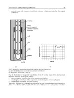
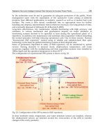
Figure 7. Constructing Site-Specific Ground Motion Response Spectrum
Source: U.S Army Corps of Engineers Response Spectra and Seismic Analysis for Concrete Hydraulic Structures EM 1110-2-6050, June 30, 1999.
Notes: Each earthquake produces a unique sequence of ground motions (accelerations) that may last several seconds or longer. The record of ground motion, captured on
an accelerograph, appears as a jagged-shaped line that represents the peak values of acceleration/de-acceleration. The ground motion response spectrum represents the
range of multiple earthquake records.
Nuclear Power Plant Design and Seismic Safety Considerations
Congressional Research Service 21
Design Response Spectra for Seismic Design of Nuclear
Power Plants
Each earthquake produces a spectrum of ground motions that vary in frequency and acceleration.
The seismic spectra important to nuclear power plant design are peak ground accelerations
between 5 and 10 Hz. The NRC has developed Design Response Spectra statistically from
response spectra of past strong motion earthquakes. The former Atomic Energy Commission
(AEC) (the NRC’s predecessor) published Regulatory Guide 1.60, Design Response Spectra of
Nuclear Power Reactors in 1973 to provide spectral shapes for horizontal and vertical ground
movements that designs must respond to (design response).
A Safe Shutdown Earthquake is defined by 10 CFR 100 Appendix A as the response spectra
corresponding to the maximum vibratory accelerations at the elevations of the nuclear power
plant structural foundations. NRC may credit nuclear power plant foundations with a 5%
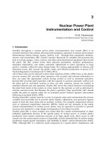
dampening affect in reducing the transmission of ground accelerations. In the example of Figure
8, the range of maximum accelerations (g) is plotted against the range of corresponding
frequencies (Hz) for the Surry Nuclear Power Plant containment building.
Figure 8. NRC Site Seismic Design Response Spectra
(U.S. NRC Regulatory Guide 1.60 Design Response Spectra─5% damping)
Source: U.S. NRC, Structural Seismic Fragility Analysis of the Surry Containment, Figure 3.1 NUREG/CR-6783,
June 2002.
Notes: The seismic spectrum important to nuclear power plant design is characterized by two intervals—peak
ground acceleration and spectral acceleration averaged between 5 and 10 Hz. The NRC considers that plant
foundations reduce the transmission of ground accelerations and credits the foundations with a 5% dampening
affect.
The NRC requires that nuclear plant designs account for site-specific ground motions and has
specified a minimum ground motion level for nuclear plant designs. The NRC Regulatory Guide