Character Animation with Direct3D- P9 pptx
Bạn đang xem bản rút gọn của tài liệu. Xem và tải ngay bản đầy đủ của tài liệu tại đây (526.1 KB, 20 trang )
146 Character Animation with Direct3D
//Create Rigid Body
btRigidBody *body = new btRigidBody(mass, ms, cs, localInertia);
//Add the new body to the dynamics world
pDynamicsWorld->addRigidBody(body);
Then to run the simulation all you need to do is call the stepSimulation()
function each frame, like this:
pDynamicsWorld->stepSimulation(deltaTime);
That’s it! The rigid body you have now created will be simulated each frame,
colliding with other rigid bodies, etc. However, you still won’t see anything on the
screen because the box is nothing but a logical representation. You need to hook up
the current motion state of the rigid body to a mesh. In the next example I create
a rigid body for the Oriented Bounding Box (OBB) class that was covered in the
previous chapter. So, each frame the rigid body is updated using the Bullet physics
library and then rendered using DirectX like this:
void OBB::Render()
{
//Get Motion state from rigid body
btMotionState *ms = m_pBody->getMotionState();
if(ms == NULL)return;
//Convert the motion state to a DX matrix
//and use it to set the world transform
pEffect->SetMatrix("matW", &BT2DX_MATRIX(*ms));
//Render the mesh as usual using whichever lighting technique
D3DXHANDLE hTech = pEffect->GetTechniqueByName("Lighting");
pEffect->SetTechnique(hTech);
pEffect->Begin(NULL, NULL);
pEffect->BeginPass(0);
m_pMesh->DrawSubset(0);
pEffect->EndPass();
pEffect->End();
}
You’ll find the source code for the first example using the Bullet physics engine
in Example 7.1.
Please purchase PDF Split-Merge on www.verypdf.com to remove this watermark.
CONSTRAINTS
After that little detour of getting to know the Bullet physics library, it is time to
get back to what I was trying to achieve in this chapter: ragdoll animation! You
need to choose some of the major bones of the character and create a physical
representation for them that can be simulated in the physics engine. Then as the
ragdoll is simulated, the position and orientation are updated for the bones using
the transforms taken from the rigid bodies, before rendering the mesh. Sounds
easy? Well, not quite. It takes a lot of effort to make ragdoll animation look good
and free from artifacts. You should also note that not all bones in the character
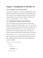
are simulated (such as finger bones and other small bones). Figure 7.6 shows a
picture of a character and its ragdoll setup.
Chapter 7 Ragdoll Simulation 147
EXAMPLE 7.1
This example integrates the Bullet physics engine into a Direct3D applica-
tion. In this example, 100 boxes of different sizes are dropped from the “sky”
and collide with the ground plane and with each other. Try to expand this example to
include shapes other than just boxes—for example, cylinders and spheres (there are
corresponding functions in DirectX to create sphere and cylinder meshes).
Please purchase PDF Split-Merge on www.verypdf.com to remove this watermark.
You don’t necessarily have to use boxes as in Figure 7.6. You can also use cylin-
ders, capsules, or any other shape you see fit. Later on I will cover in more detail how
to position the shapes to match the skeleton. However, should you run the simulation
after just placing boxes, they would all fall to the floor, disjointed from each other.
You need some form of “connection” between the under arm and the upper arm, for
example. This is where constraints come into the picture. A constraint is just what it
sounds like; it is a rule telling two rigid bodies how they can move in relation to each
other. The two simplest forms of constraints are shown in Figure 7.7.
148
Character Animation with Direct3D
FIGURE 7.6
An example ragdoll setup.
FIGURE 7.7
The ball and hinge joints.
Please purchase PDF Split-Merge on www.verypdf.com to remove this watermark.
Bullet supports the following constraints:
Point-to-point constraint (a.k.a. ball joint)
Hinge constraint
Twist cone constraint
6 degrees of freedom (DoF) constraint
The ball joint doesn’t have any restrictions on angle or twist amount, whereas the
hinge joint allows no twisting of the connected rigid bodies. The twist cone is a mix
between the ball and hinge joints. With the twist cone constraint, you can specify the
angle range and twist amount allowed (which is very useful when creating a ragdoll).
With the 6DoF constraint, you can specify exactly the angle ranges of each DoF. This
is a bit more functionality than you need to implement a simple ragdoll animation,
but check out the Bullet SDK for more information on these constraints.
Here’s how you would create a simple constraint with the Bullet physics engine.
Let’s assume you have two rigid bodies (
A and B) created as shown in the previous
example. You would create a hinge constraint between them like this:
//Set transforms and axis for the hinge (for each rigid body)
btTransform localA, localB;
localA.setIdentity();
localB.setIdentity();
localA.getBasis().setEulerZYX(0,0,0);
localA.setOrigin(btVector3(0.0f, -0.5f, 0.0f));
localB.getBasis().setEulerZYX(0,0,0);
localB.setOrigin(btVector3(0.0f, 0.5f, 0.0f));
//Create Hinge Constraint
btHingeConstraint *hingeC;
hingeC = new btHingeConstraint(A, B, localA, localB);
hingeC->setLimit(-0.5f, 0.5f);
//Add the constraint to the dynamics world
pDynamicsWorld->addConstraint(hingeC, true);
That’s how simple it is to add a constraint between two rigid bodies. The con-
straint limit specifies how much the hinge can bend back and forth. Example 7.2
shows you how this is done with the twist cone and ball joint constraints.
Chapter 7 Ragdoll Simulation 149
Please purchase PDF Split-Merge on www.verypdf.com to remove this watermark.
CONSTRUCTING THE RAGDOLL
Now that you know how to connect physical rigid bodies using constraints, the
next step of creating a ragdoll is not far off…in theory. All you have to do is to
create a series of boxes (or other shapes) connected via different constraints.
However, in practice it is slightly more difficult than that. First you need to make
sure that the boxes match the skeleton (and the character mesh) as close to
perfect as possible. Otherwise you would get weird results updating the bone
hierarchy of the character using an ill-fitting physical representation. So the
problem you are about to face is the one shown in Figure 7.8.
150
Character Animation with Direct3D
EXAMPLE 7.2
This example implements some of the most common constraints available
to you in the Bullet library. A large number of boxes are created, connected
into a long “string.” Run the simulation many times and observe the difference
between the hinge, the point, and the twist-cone constraints. Also, play around with
the limits of the constraints and see the effect it gives. Be sure to study how the con-
straints are created, since you’ll need a good understanding of this in the next section
where a ragdoll is created.
Please purchase PDF Split-Merge on www.verypdf.com to remove this watermark.
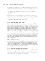
In Figure 7.8 you see a part of a character—namely, an arm. For a working
ragdoll animation you must create a physical representation of the character that
you can simulate in your physics engine. At each frame you update the skeleton of
the character to match the physical representation and, voila!, You’ve got yourself a
ragdoll. For the purpose of creating, updating, simulating, and rendering a ragdoll,
I’ve created the following class with the somewhat unimaginative name
RagDoll:
class RagDoll : public SkinnedMesh
{
public:
RagDoll(char fileName[], D3DXMATRIX &world);
~RagDoll();
void InitBones(Bone *bone);
void Release();
void Update(float deltaTime);
Chapter 7 Ragdoll Simulation 151
FIGURE 7.8
Solid character arm mesh (top). Arm wireframe and bones
(middle). Arm wireframe and physical representation (bottom).
Please purchase PDF Split-Merge on www.verypdf.com to remove this watermark.
void Render();
void UpdateSkeleton(Bone* bone);
OBB* CreateBoneBox(Bone* parent, Bone *bone,
D3DXVECTOR3 size, D3DXQUATERNION rot);
void CreateHinge(Bone* parent, OBB* A, OBB* B,
float upperLimit, float lowerLimit,
D3DXVECTOR3 hingeAxisA, D3DXVECTOR3 hingeAxisB,
bool ignoreCollisions=true);
void CreateTwistCone(BONE* parent, OBB* A, OBB* B,
float limit, D3DXVECTOR3 hingeAxisA,
D3DXVECTOR3 hingeAxisB,
bool ignoreCollisions=true);
private:
vector<OBB*> m_boxes; //Boxes for physics simulation
};
I’ll cover the more technical functions and creation of this class throughout the
coming sections. But first there are some challenges you’ll face when approaching
this problem. For example, how do you place the Oriented Bounding Boxes so that
they fit the mesh as closely as possible? You could, of course, attempt an algorithmic
approach. This might be best if you need to create physical representations for a
large number of characters, or if your characters are generated or randomized in
some way. In that case you should probably traverse through the bones and deter-
mine which ones are big enough to merit a physical representation (remember,
small bones like fingers are ignored). Next you would have to find the vertices linked
to this bone and, for example, use Principal Component Analysis (PCA) to fit an
Oriented Bounding Box to the bone and its vertices [VanVerth04]. This is outside
the scope of this book, however, so I’ll stick with the old-fashioned way of doing
things: “by hand.”
Even the “by hand” approach will need some supporting calculations to place
the Oriented Bounding Box as optimally as possible. See Figure 7.9.
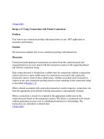
With the “by hand” fitting scheme I will only supply the size of the Oriented
Bounding Box and use the orientation of the bone itself. Having the size and the
orientation, you only need to calculate the position of the OBB before you can
place it in the world. Figure 7.9 shows a simplified 2D image of a character’s arm.
If you need to place the upper arm bounding box, you just take the two end points
(points A and B) of the upper arm bone and place the bounding box at the middle
point of these two end points. The following piece of code comes from the Ragdoll
class and does just this:
152
Character Animation with Direct3D
Please purchase PDF Split-Merge on www.verypdf.com to remove this watermark.
struct Bone: public D3DXFRAME
{
D3DXMATRIX CombinedTransformationMatrix;
OBB *m_pObb;
};
OBB* RagDoll::CreateBoneBox(Bone* parent, Bone *bone,
D3DXVECTOR3 size, D3DXQUATERNION rot)
{
if(bone == NULL || parent == NULL)
return NULL;
//Get bone starting point
D3DXMATRIX &parentMat = parent->CombinedTransformationMatrix;
D3DXVECTOR3 parentPos(parentMat(3, 0),
parentMat(3, 1),
parentMat(3, 2));
//Get bone end point
D3DXMATRIX &boneMat = bone->CombinedTransformationMatrix;
D3DXVECTOR3 bonePos(boneMat(3, 0), boneMat(3, 1), boneMat(3, 2));
Chapter 7 Ragdoll Simulation 153
FIGURE 7.9
Fitting an OBB to a bone.
Please purchase PDF Split-Merge on www.verypdf.com to remove this watermark.
//Extract the rotation from the bone
D3DXQUATERNION q;
D3DXVECTOR3 p, s;
D3DXMatrixDecompose(&s, &q, &p, &parentMat);
//Offset rotation (in some cases only)
q *= rot;
D3DXQuaternionNormalize(&q, &q);
//Calculate the middle point
p = (parentPos + bonePos) * 0.5f;
//Create new OBB
OBB *obb = new OBB(p, size, q, true);
//Add the OBB to the physics engine
physicsEngine.GetWorld()->addRigidBody(obb->m_pBody);
//Add OBB to the ragdoll’s own list
m_boxes.push_back(obb);
//Connect the bone to the OBB
parent->m_pObb = obb;
return obb;
}
As you can see, I’ve added a pointer to an OBB in the Bone structure. Each bone
now has a pointer to an Oriented Bounding Box. Through this pointer the bone can
retrieve the current position and orientation of the physical representation as the
simulation runs. Other than this, the OBB is created and placed as explained earlier.
Creating the Oriented Bounding Boxes is, of course, only the first step. If you run
the physics simulation now, you would see the boxes fall to the floor disjointed
from each other. Next you’ll need to connect them in a proper manner before you
have a ragdoll. This is the real tricky part and the hardest part to get right (i.e., to
produce good-looking results). As covered earlier in Example 7.2, I’ll use the hinge
and twist cone constraints to hold the boxes in place. Take another look at Figure
7.9. When you place the constraints you will now place them in between the boxes
instead, in the points A, B, and C. The following function in the Ragdoll class
creates a twist cone constraint between two Oriented Bounding Boxes (a similar
function exists to create a hinge constraint):
154
Character Animation with Direct3D
Please purchase PDF Split-Merge on www.verypdf.com to remove this watermark.
void RagDoll::CreateTwistCone(Bone* parent, OBB* A, OBB* B,
float limit, D3DXVECTOR3 hingeAxisA,
D3DXVECTOR3 hingeAxisB, bool ignoreCollisions)
{
if(parent == NULL || A == NULL || B == NULL)
return;
//Extract the constraint position
D3DXMATRIX &parentMat = parent->CombinedTransformationMatrix;
btVector3 hingePos(parentMat(3, 0),
parentMat(3, 1),
parentMat(3, 2));
D3DXVECTOR3 hingePosDX(parentMat(3, 0),
parentMat(3, 1),
parentMat(3, 2));
//Get references to the two rigid bodies you want to connect
btRigidBody *a = A->m_pBody;
btRigidBody *b = B->m_pBody;
//Get world matrix from the two rigid bodies
btTransform aTrans, bTrans;
a->getMotionState()->getWorldTransform(aTrans);
b->getMotionState()->getWorldTransform(bTrans);
D3DXMATRIX worldA = BT2DX_MATRIX(aTrans);
D3DXMATRIX worldB = BT2DX_MATRIX(bTrans);
//Calculate pivot point for both rigid bodies
D3DXVECTOR3 offA, offB;
D3DXMatrixInverse(&worldA, NULL, &worldA);
D3DXMatrixInverse(&worldB, NULL, &worldB);
D3DXVec3TransformCoord(&offA, &hingePosDX, &worldA);
D3DXVec3TransformCoord(&offB, &hingePosDX, &worldB);
btVector3 offsetA(offA.x, offA.y, offA.z);
btVector3 offsetB(offB.x, offB.y, offB.z);
//Set constraint axis
aTrans.setIdentity();
bTrans.setIdentity();
aTrans.setOrigin(offsetA);
bTrans.setOrigin(offsetB);
aTrans.getBasis().setEulerZYX(
hingeAxisA.x, hingeAxisA.y, hingeAxisA.z);
Chapter 7 Ragdoll Simulation 155
Please purchase PDF Split-Merge on www.verypdf.com to remove this watermark.
bTrans.getBasis().setEulerZYX(
hingeAxisB.x, hingeAxisB.y, hingeAxisB.z);
//Create new twist cone constraint
btConeTwistConstraint *twistC;
twistC = new btConeTwistConstraint(*a, *b, aTrans, bTrans);
//Set Constraint limits
twistC->setLimit(limit, limit, 0.05f);
//Add constraint to the physics engine
physicsEngine.GetWorld()->addConstraint(twistC, true);
}
This function is generally pretty straightforward. The only tricky thing in here
is to calculate the pivot point for the two rigid bodies. Since the pivot point needs
to be in the local space of the rigid body, you have to multiply the world-space
location of the pivot point with the inverse of the rigid body’s world matrix. Next
I set the constraint axes and limits, and finally the constraint is added to the
physics simulation. There’s now only one final thing left to do, and that is to make
use of these two functions and create the ragdoll. The following is an excerpt from
the constructor of the
RagDoll class:
RagDoll::RagDoll(char fileName[], D3DXMATRIX &world) : SkinnedMesh()
{
//Load the character from an .x file
SkinnedMesh::Load(fileName);
//Set beginning pose
SetPose(world);
//Find bones to use in the construction of the ragdoll
//
Bone* U_R_Arm=(Bone*)D3DXFrameFind(m_pRootBone,"Upper_Arm_Right");
Bone* L_R_Arm=(Bone*)D3DXFrameFind(m_pRootBone,"Lower_Arm_Right");
Bone* R_Hand=(Bone*)D3DXFrameFind(m_pRootBone, "Hand_Right");
//
D3DXQUATERNION q;
D3DXQuaternionIdentity(&q);
156 Character Animation with Direct3D
Please purchase PDF Split-Merge on www.verypdf.com to remove this watermark.
//
//Right arm (two bounding boxes)
OBB* o03 = CreateBoneBox(U_R_Arm, L_R_Arm,
D3DXVECTOR3(0.3f, 0.12f, 0.12f), q);
OBB* o04 = CreateBoneBox(L_R_Arm, R_Hand,
D3DXVECTOR3(0.3f, 0.12f, 0.12f), q);
//
//Constraints
//
CreateTwistCone(U_R_Arm, o08, o03, D3DX_PI * 0.6f,
D3DXVECTOR3(0.0f, D3DX_PI * 0.75f, 0.0f),
D3DXVECTOR3(0.0f, 0.0f, 0.0f));
CreateHinge(L_R_Arm, o03, o04, 0.0f, -2.0f,
D3DXVECTOR3(0.0f, 0.0f, D3DX_PI * 0.5f),
D3DXVECTOR3(0.0f, 0.0f, D3DX_PI * 0.5f));
}
To keep this code excerpt from taking up too many pages, I show only how the
arm of the ragdoll is set up. You’ll find the complete initialization of the ragdoll in the
next example. However, as you can see, the character is first loaded as a skinned mesh
from an .x file. Next I set the pose I want to use as the bind pose for the character
while creating the ragdoll. Then I use the
CreateBoneBox(), CreateTwistCone(), and
CreateHinge() functions to create the full physical representation of the character. As
always, you’ll find the full code for the ragdoll setup in Example 7.3.
Chapter 7 Ragdoll Simulation 157
Please purchase PDF Split-Merge on www.verypdf.com to remove this watermark.
UPDATING THE CHARACTER MESH FROM THE RAGDOLL
The final step before having complete ragdoll animation is of course to connect
the bone hierarchy to the physical representation. This way, the bones (and in
turn, the mesh) will be updated as the ragdoll flails about. Remember that you use
many fewer Oriented Bounding Boxes than you use bones to avoid simulating the
small unnecessary bones like fingers and toes, etc. However, if the hand bone (the
parent of a finger bone) has a physical representation, then when the combined
transformation matrix of this bone is updated, its child bone(s) will also be
updated. Already in the previous section of this chapter I added a pointer to an
OBB in the
Bone structure. Now that I want to be able to update a bone hierarchy,
some more information is needed in this structure:
158
Character Animation with Direct3D
EXAMPLE 7.3
In Example 7.3 there’s finally something resembling a character. The ragdoll
here is built up by Oriented Bounding Boxes bound together by hinge and
twist cone constraints. As the physics simulation runs, the ragdoll seems to fall in a
(somewhat) realistic manner. Use the technique shown in this example to try and
build another ragdoll (perhaps something other than a biped).
Please purchase PDF Split-Merge on www.verypdf.com to remove this watermark.
struct Bone: public D3DXFRAME
{
D3DXMATRIX CombinedTransformationMatrix;
//Pointer to an OBB (if any)
OBB *m_pObb;
//The bone’s pivot point (offset from OBB center)
D3DXVECTOR3 m_pivot;
//Original orientation of this bone
D3DXQUATERNION m_originalRot;
};
You’ll see later how I use the pivot point and the original orientation of the
bone to calculate the new position and orientation based on the bone’s OBB. I
have already covered the creation of the Oriented Bounding Boxes and how they
are assigned to their corresponding bones. Now all you need to do is calculate the
new bone matrices as the boxes are simulated by the physics engine. First off, let’s
start with the position of the bones.
G
ETTING A BONE’S POSITION FROM AN OBB
Before you continue further, have another look at how the revised
OBB class now looks
(a lot has changed in this class since Chapter 6). Some of the ragdoll-specific functions
of this class will be explained in further detail throughout the rest of this chapter.
class OBB
{
public:
OBB(D3DXVECTOR3 pos,
D3DXVECTOR3 size,
bool dynamic=true);
OBB(D3DXVECTOR3 pos,
D3DXVECTOR3 size,
D3DXQUATERNION rot,
bool dynamic=true);
void Init(D3DXVECTOR3 pos,
D3DXVECTOR3 size,
D3DXQUATERNION rot,
bool dynamic=true);
Chapter 7 Ragdoll Simulation 159
Please purchase PDF Split-Merge on www.verypdf.com to remove this watermark.
~OBB();
void Release();
void Update(float deltaTime);
void Render();
D3DXVECTOR3 SetPivot(D3DXVECTOR3 pivot);
D3DXVECTOR3 GetPivot(D3DXVECTOR3 pivot);
D3DXQUATERNION GetRotation(D3DXQUATERNION orgBoneRot);
public:
btRigidBody *m_pBody;
D3DXVECTOR3 m_size;
D3DXQUATERNION m_orgRot;
private:
ID3DXMesh *m_pMesh;
};
To be able to calculate the bone position on the fly from an OBB’s transfor-
mation matrix, you need to first calculate the bone’s pivot point. This is, in other
words, the position of the bone in the OBB world space. The pivot point is
calculated at the initialization of the ragdoll and then used during runtime to
calculate the new position for the bone. To get this initial pivot point I’ve added
the following function to the OBB class:
D3DXVECTOR3 OBB::SetPivot(D3DXVECTOR3 pivot)
{
btMotionState *ms = m_pBody->getMotionState();
if(ms == NULL)return D3DXVECTOR3(0.0f, 0.0f, 0.0f);
D3DXMATRIX world = BT2DX_MATRIX(*ms);
D3DXVECTOR3 newPivot;
D3DXMatrixInverse(&world, NULL, &world);
D3DXVec3TransformCoord(&newPivot, &pivot, &world);
return newPivot;
}
Here I simply extract the world matrix from the initial motion state of the box.
Next I multiply the position of the bone (the
pivot parameter) with the inverse of the
OBB’s world matrix. The result (the pivot point in relation to the OBB) is returned.
In runtime you should use the following function to do the exact opposite of the
SetPivot() function:
160
Character Animation with Direct3D
Please purchase PDF Split-Merge on www.verypdf.com to remove this watermark.
D3DXVECTOR3 OBB::GetPivot(D3DXVECTOR3 pivot)
{
btMotionState *ms = m_pBody->getMotionState();
if(ms == NULL)return D3DXVECTOR3(0.0f, 0.0f, 0.0f);
D3DXMATRIX world = BT2DX_MATRIX(*ms);
D3DXVECTOR3 newPivot;
D3DXVec3TransformCoord(&newPivot, &pivot, &world);
return newPivot;
}
Here the pivot you supply is the one that was calculated in the initialization
using the previous function, but in runtime the motion state of the box has changed
and so the result from this function is the new position for the bone. Next you need
to perform this exact operation, but for the orientation instead.
G
ETTING A BONE’S ORIENTATION FROM AN OBB
This one is perhaps a little trickier since it involves some quaternion math. But the
thought process is the same. You should compare the box’s current orientation
with its original orientation, getting the change in orientation, and apply it to the
bone’s original orientation. The result is a bone whose orientation matches that of
the physical representation (the box).
D3DXQUATERNION OBB::GetRotation(D3DXQUATERNION orgBoneRot)
{
btMotionState *ms = m_pBody->getMotionState();
btTransform t;
ms->getWorldTransform(t);
D3DXQUATERNION rot = BT2DX_QUATERNION(t.getRotation());
D3DXQUATERNION invOrgRot;
D3DXQuaternionInverse(&invOrgRot, &m_orgRot);
D3DXQUATERNION diff = invOrgRot * rot;
return orgBoneRot * diff;
}
Here the current orientation of the box is extracted. Then you calculate the
delta quaternion—i.e., the rotation operation that rotates the box’s original ori-
entation to its current orientation. This is done by multiplying the inverse of the
starting orientation with destination orientation. Then this delta quaternion is
Chapter 7 Ragdoll Simulation 161
Please purchase PDF Split-Merge on www.verypdf.com to remove this watermark.
applied to the original orientation of the bone. This operation rotates the bone
from its original orientation as much as the box’s orientation has changed from
its original orientation. The orientation is calculated this way using the difference
between the current and the original orientations of the box, since the bone and
the box might have had different orientations to begin with. Finally you just need
to traverse through the bone hierarchy and update the transformation matrices.
U
PDATING THE BONE HIERARCHY
To update the bone hierarchy, all you need to do is traverse the hierarchy each
frame, query the position and orientation of any bones connected to an OBB, and
update the transformation matrix of that bone. Once a bone’s matrix has been
updated, it is also important to pass this change forward to any child bones that bone
may have (using the
UpdateMatrices() function). To do all this I’ve created the
UpdateSkeleton() function in the Ragdoll class which should be called each frame:
void RAGDOLL::UpdateSkeleton(BONE* bone)
{
if(bone == NULL)
return;
if(bone->m_pObb != NULL)
{
//Calculate new position for the bone
D3DXMATRIX pos;
D3DXVECTOR3 pivot = bone->m_pObb->GetPivot(bone->m_pivot);
D3DXMatrixTranslation(&pos, pivot.x, pivot.y, pivot.z);
//Calculate new orientation for the bone
D3DXMATRIX rot;
D3DXMatrixRotationQuaternion(&rot,
&bone->m_pObb->GetRotation(bone->m_originalRot));
//Combine to create new transformation matrix
bone->CombinedTransformationMatrix = rot * pos;
//Update children bones with our new transformation matrix
if(bone->pFrameFirstChild != NULL)
UpdateMatrices((BONE*)bone->pFrameFirstChild,
&bone->CombinedTransformationMatrix);
}
162 Character Animation with Direct3D
Please purchase PDF Split-Merge on www.verypdf.com to remove this watermark.
//Traverse the rest of the bone hierarchy
UpdateSkeleton((BONE*)bone->pFrameSibling);
UpdateSkeleton((BONE*)bone->pFrameFirstChild);
}
Done! That about wraps it up! If you run the simulation now, the mesh will
follow the physical representation of the character and seemingly fall and interact
with the environment, etc. You can see a series of images in Figure 7.10 where a
character falls and is updated at runtime using the ragdoll animation presented in
this chapter.
Chapter 7 Ragdoll Simulation 163
FIGURE 7.10
A sequence of images from the ragdoll simulation.
Please purchase PDF Split-Merge on www.verypdf.com to remove this watermark.
To the left in Figure 7.10 you see the character mesh and to the right is the
corresponding physical representation. Check out Example 7.4 where you’ll find
the complete ragdoll simulation code.
CONCLUSIONS
Although this chapter is perhaps the most technically advanced in this book, it is
also one of the most rewarding. By giving the character a physical representation,
you can simulate the character in real-time as he falls or gets hit, etc. As cool as this
may seem, the simple Ragdoll example presented in this chapter is still far from the
quality you see in commercial games. However, I hope that this serves as a good
primer or starting point for you to implement your own ragdoll animation. There
164
Character Animation with Direct3D
EXAMPLE 7.4
Here at last is the Ragdoll example. The character model has been skinned
to the bone hierarchy (just like in Chapter 3 and onward). However, this time
you don’t update the character from a pre-created animation, but rather on the fly using
the Bullet physics engine. This is still a pretty rough example. Spend some time to
tweak the myriad of variables to see if you can make the simulation look better!
Please purchase PDF Split-Merge on www.verypdf.com to remove this watermark.
are several improvements to be made to this system. For example, you may want to
try using shapes other than boxes. The Bullet engine’s Ragdoll example used cap-
sules, for instance. Another thing you should look into is damping and figuring out
when to turn off the physical simulation of a ragdoll (both to save CPU cycles and
to stop that micro twitching you can see in the examples of this chapter). Check out
the Bullet library (or whatever physics engine you chose to use) documentation for
more information. In the next chapter I will move away from skeletal animation
and will cover morphing animation. Over the course of the next couple of chapters,
I will show you how to implement organic animation, such as facial expression,
talking characters, and more.
CHAPTER 7 EXERCISES
Explore the Bullet physics library. Try to implement a bullet (a force) issuing
from the mouse cursor that affects the items in any of the examples in this
chapter.
Add more geometry to the scene with which the ragdoll can collide.
Try to mess with the gravity of the physics engine. For example, try zero-
gravity simulations (which look pretty cool with the ragdoll).
Explore other shapes, such as cylinders and capsules instead of boxes.
Try different configurations for the joints. Make use of the hinge, twist cone,
and perhaps even the Bullet engine’s 6DoF constraint.
Extend Example 7.4 to simulate more than one ragdoll.
Implement damping of the ragdoll.
FURTHER READING
[VanVerth04] Van Verth, Jim, “Using Covariance Matrix for Better-Fitting Bounding
Objects.” Game Programming Gems 4, Charles River Media, 2004.
Chapter 7 Ragdoll Simulation 165
Please purchase PDF Split-Merge on www.verypdf.com to remove this watermark.