3D Graphics with OpenGL ES and M3G- P21 pps
Bạn đang xem bản rút gọn của tài liệu. Xem và tải ngay bản đầy đủ của tài liệu tại đây (170.17 KB, 10 trang )
184 OPENGL ES TRANSFORMATION AND LIGHTING CHAPTER 8
The mode must be one of GL_MODELVIEW, GL_PROJECTION,orGL_TEXTURE.
In this section we concentrate on the modelview and projection mat rices; texture trans-
formations are discussed in Section 8.2.3. From OpenGL ES 1.1 onward GL_MATRIX_
PALETTE_OES is also optionally available (see Section 10.4.3). The color matrix that
exists in OpenGL is not supported.
All mat rices are 4 × 4 matrices, and are stored in column-first order. The current matrix
can be replaced by calling
void glLoadMatrix{fx}(const T * m)
where m is an array of 16 floating-point or fixed-point numbers, ordered as follows:
⎡
⎢
⎢
⎢
⎣
m[0] m[4] m[8] m[12]
m[1] m[5] m[9] m[13]
m[2] m[6] m[10] m[14]
m[3] m[7] m[11] m[15]
⎤
⎥
⎥
⎥
⎦
.
(8.3)
It is possible to multiply a new matrix with the current matrix using
void glMultMatrix{fx}(const T * m).
If C is the current matrix, calling glMultMatrix with M computes C := CM, that is,
the multiplication is from the right side.
As described in Chapter 2, it is often useful to separately transform the vertices from the
object coordinates to the world coordinates, and then transform the vertices from the
world coordinates to the eye coordinates. The matrices can then be used as follows:
GLfloat world_to_eye_matrix[16], object_to_world_matrix[16];
/* calculate matrices */
/* set up modelview matrix and draw */
glMatrixMode( GL_MODELVIEW );
glLoadMatrixf( world_to_eye_matrix );
glMultMatrixf( object_to_world_matrix );
glDrawArrays( GL_TRIANGLES, 0, n );
The convenience function
void glLoadIdentity(void )
replaces the current matrix with the identity matr ix (see Equation (2.14)), while the fol-
lowing functions
void glTranslate{fx}(T x, T y, T z)
void glRotate{fx}(T angle, T x, T y, T z)
void glScale{fx}(T x, T y, T z)
SECTION 8.2 VERTEX TRANSFORMATION PIPELINE 185
multiply thecurrent matr ix with oneof Equations (2.17), (2.22), and(2.24). Thefunctions
void glFrustum{fx}(T le ft, T right, T bottom, T top, T near, T far)
void glOrtho{fx}(T le ft, T right, T bottom, T top, T near, T far)
are used to set up the perspective projection matrix of Equation (2.35) or orthographic
projection matrix of Equation (2.39), respectively. The last two arguments set the distance
to the near and far frustum clipping planes, while the first four arguments describe where
the viewing frustum intersects the near plane. The following example code sets up the
projection matrix for a camera with near at 10, far at 60, with a WINDOW_WIDTH ×
WINDOW_HEIGHT window, and a 60
◦
horizontal frustum opening angle:
GLfloat half_w, half_h, aspect;
/* window size from app or OS */
aspect = GLfloat( WINDOW_WIDTH ) / GLfloat( WINDOW_HEIGHT );
/* near * sin( angle/2)=10*sin( 30)=5*/
half_w = 5.0f;
half_h = half_w / aspect;
glMatrixMode( GL_PROJECTION );
glLoadIdentity();
glFrustum( -half_w, half_w, -half_h, half_h, 10, 60 );
/* good practice to leave in modelview mode, used more often */
glMatrixMode( GL_MODELVIEW );
8.2.2 TRANSFORMING NORMALS
As described in Section 2.2.4, normal vectors are not transformed using the same trans-
formation as the vertices. OpenGL calculates the inverse transpose for the 3 × 3 upper left
corner of the modelview matrix and applies the result to the normal vector.
The length of the normals may change during this process. However, if the modelview
transformation is a rigid transformation, that is, it only consists of a rotation and a trans-
lation, and no scale or shear, it does not affect the length of the normal vector. By default
OpenGL assumes this and does not normalize the vertex normals before applying the
lighting equations.
However, if the modelview matrix includes a scaling component, the lengths do change.
For example, if the model is scaled up the nor mals will shrink as the normals are trans-
formed using the tr ansposed inverse of the modelview matrix. The effect isthat the objects
appear surprisingly dark. If there is only uniform scaling, i.e., no nonuniform scales or
shears, it is possible to calculate a correct rescaling factor from the modelview matrix, and
apply that to all normals after the transformation. This is enabled by
glEnable( GL_RESCALE_NORMAL );
However, in general, if nonuniform scaling or shearing is included, or if the normals were
not of unit length to start with, the normal vectors have to be normalized individually,
186 OPENGL ES TRANSFORMATION AND LIGHTING CHAPTER 8
by calculating their lengths and dividing the normal by the length. This is by far the most
expensive option, and the geomet ry pipeline can be instructed to do it by
glEnable( GL_NORMALIZE );
8.2.3 TEXTURE COORDINATE TRANSFORMATION
ThetexturematrixmodeisturnedonwithglMatrixMode( GL_TEXTURE ), but
as every texture unit has its own matrix, the active unit must first be specified with
void glActiveTexture(GLenum tex ture)
with texture being GL_TEXTUREi,where0 ≤ i<the value of GL_MAX_TEXTURE_
UNITS (see the example in Section 9.2.6).
After the texture matrix transformation, the s and t components of a texture coordinate
are divided by the q component. The OpenGL ES specification does not require an imple-
mentation to do this division on a per-pixel basis—the implementation is allowed to do
the division just once per vertex. Taking this shortcut may cause visible differences and
artifacts between implementations. The transformed r coordinate is discarded, as three-
dimensional textures are not supported in OpenGL ES.
While desktop OpenGL supports creation of texture coordinates, for example so that they
come from the vertex locations in eye coordinates, or that they are set up for reflections,
OpenGL ES does not have this mechanism. Instead, the application must set the appro-
priate texture coordinates itself. Some of the effects of the texture coordinate generation
can be emulated by copying the vertex locations into texture coordinates, and then setting
up the texture matrix appropriately.
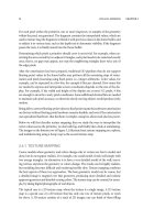
Below is an example code that draws a simple fake glass object on the screen (see Figure 8.3
for a screenshot). The texture that is used for rendering the glass object is drawn as the
background first:
static const GLbyte back_coords[] =
{
1,1,
1,0,
0,1,
0,0
};
static const GLfixed object_coords[] =
{
normalized X,Y,Z coordinates
};
void render(void)
{
glClear( GL_COLOR_BUFFER_BIT | GL_DEPTH_BUFFER_BIT );
SECTION 8.2 VERTEX TRANSFORMATION PIPELINE 187
Figure 8.3: Screen shot of the texture matrix manipulation example code. (Also in the color plate.)
/* draw background with two textured triangles */
glMatrixMode( GL_TEXTURE );
glLoadIdentity();
glMatrixMode( GL_PROJECTION );
glLoadIdentity();
glMatrixMode( GL_MODELVIEW );
glLoadIdentity();
glScalef( 2.f, — 2.f, 0.f );
glTranslatef( — 0.5f, — 0.5f, 0.f );
glVertexPointer( 2, GL_BYTE, 0, back_coords );
glTexCoordPointer( 2, GL_BYTE, 0, back_coords );
glDrawArrays( GL_TRIANGLE_STRIP, 0, 4 );
Now the object in front is rendered. First the projection matrix is restored and modelview
matrix is set so that the object rotates as time passes:
/* draw the object in front */
glMatrixMode( GL_PROJECTION );
glLoadIdentity();
glFrustumf( — 1.f, 1.f, — 1.f, 1.f, 3.f, 1000.f );
glMatrixMode( GL_MODELVIEW );
glLoadIdentity();
glTranslatef( 0, 0, — 5.f) ;
glRotatef( time*25, 1.f, 1.f, 0.f );
glRotatef( time*15, 1.f, 0.f, 1.f );
188 OPENGL ES TRANSFORMATION AND LIGHTING CHAPTER 8
The same normalized coordinate set is used as vertex coordinates and texture coordinates.
The goal is to rotate the texture coordinates to the same orientation as the vertex coor-
dinates and then use the resulting x and y components as the texture coordinates. This
is accomplished by using the same rotation calls as for the modelview matrix and then
scaling and translating the coordinates from [−1,1] range to [0,1] range:
glMatrixMode( GL_TEXTURE );
glLoadIdentity();
glTranslatef( 0.5f, 0.5f, 0.f ); /* [ — 0.5,0.5] -> [0,1] */
glScalef( 0.5f, — 0.5f, 0.f ); /* [ — 1,1] -> [ — 0.5,0.5] */
glRotatef( time*25, 1.f, 1.f, 0.f ); /* same rotate calls */
glRotatef( time*15, 1.f, 0.f, 1.f);
glVertexPointer( 3, GL_FIXED, 0, object_coords );
glTexCoordPointer( 3, GL_FIXED, 0, object_coords );
glDrawArrays( GL_TRIANGLES, 0, 16*3 );
8.2.4 MATRIX STACKS
Section 2.3.3 introduced the concept of a matrix stack. For every type of matrix there is a
corresponding matrix stack, into which a duplicate of the current matrix can be pushed
and saved, and from which it can be restored by popping the stack. This is done using the
following calls:
void glPushMatrix(void )
void glPopMatrix(void )
A common pattern is to use glPushMatrix to duplicate the top of the stack, then apply
one of the matrix manipulation functions, perform rendering, and finally restore the stack
to its original state by calling glPopMatrix. If the matrix stack becomes full, or you try
to pop an empty stack, an error is r aised. The modelview stack is guaranteed to be at least
16 elements deep, while the other stacks are guaranteed to be at least 2 elements deep.
8.2.5 VIEWPORT TRANSFORMATION
Two functions control how projected vertex coordinates are mapped into the window
coordinates.
void glViewport(GLint x, GLint y, GLsizei width, GLsizei height)
controls the mapping on the x and y axes and determines the position and the size of the
viewport rectangle. The window is initially set to match the size of the render surface. The
function
void glDepthRange{fx}(T near, T far )
determines how the depth coordinates are mapped from the normalized device coordi-
nate range of [−1, + 1] into the depth buffer values between 0 and 1. Initially the depth
rangeissettonear = 0, far = 1, thus covering the range of the entire depth buffer.
SECTION 8.3 COLORS AND LIGHTING 189
Changing these values allows selecting only a subset of the depth buffer range. Here is an
example showing how these functions are usually called:
glViewport( 0, 0, width, height );
glDepthRangef( 0.f, 1.f );
Section 2.6 gives several examples of clever use of glDepthRange.
8.2.6 USER CLIP PLANES
The standard transformation pipeline performs clipping of primitives into the canonical
view frustum formed by the near, far, left, right, top, and bottom clipping planes. From
OpenGL ES 1.1 onward, additional, user-defined clipping planes of ar bitrary orientation
are also supported. The minimum number of planes an implementation has to support
is one, and not many implementations support more than this. The function
void glClipPlane{fx}(GLenum plane, const T * equation)
is used to define the four-component clipping plane equation. This equation, given in
object coordinates, is immediately transformed to the eye coordinate space by multiplying
it by the inverse transpose of the current modelview matrix (see Section 3.3.2). The plane
must be GL_CLIP_PLANEi where 0 ≤ i<GL_MAX_CLIP_PLANES are accepted.
The clip plane needs to be enabled by glEnable( GL_CLIP_PLANE0 ).
8.3 COLORS AND LIGHTING
In this section, we describe the OpenGL ES calls that are required to enable correct light-
ing. The principles of color and lighting are described in Section 3.2.
8.3.1 SPECIFYING COLORS AND MATERIALS
We have already described the way colors are specified in OpenGL in Section 8.1.2: either
all vertices get the same default color set by
void glColor4{fx ub}(T red, T green, T blue, T alpha)
or each vertex gets an individual color using
void glColorPointer(GLint size, GLenum type, GLsizei stride, GLvoid * pointer).
If lighting has not been turned on by calling glEnable( GL_LIGHTING ), the
vertices retain the literal colors they are assigned. However, if lighting is enabled, the sur-
faces need material properties. Section 3.2.3 describes the var ious material components:
ambient, diffuse, specular, and emissive. They can be defined by calling
void glMaterial{fx}v(GL_FRONT_AND_BACK , GLenum pname, const T * params)
190 OPENGL ES TRANSFORMATION AND LIGHTING CHAPTER 8
where params must be a pointer to an arr ay with at least four elements, interpreted as red,
green, blue, and alpha values, and pname must be one of the following values (the value
in parentheses is the corresponding default color):
GL_AMBIENT (0.2, 0.2, 0.2, 1.0)
GL_DIFFUSE (0.8, 0.8, 0.8, 1.0)
GL_SPECULAR (0.0, 0.0, 0.0, 1.0)
GL_EMISSIVE (0.0, 0.0, 0.0, 1.0)
It is also possible to use GL_AMBIENT_AND_DIFFUSE to set both the ambient and the
diffuse component at once to the same value. Note that the material values do not have
to lie within [0, 1]. However, the final colors at each vertex, after lighting but prior to
rasterization, are clamped to [0, 1]. Whereas in desktop OpenGL one may assign dif-
ferent materials to the front and the back sides of a surface, OpenGL ES only allows
the same material on both sides. Therefore, the first argument must always be set to
GL_FRONT_AND_BACK.
The shininess of the specular reflectance can be set by calling
void glMaterial{fx}(GL_FRONT_AND_BACK, GL_SHININESS, T param)
where param must be in the range [0, 128] and defaults to 0.
It is also possible for individual vertices to have different materials. If you call glEnable
(GL_COLOR_MATERIAL) the vertex color array values (set by glColorPointer)
are copied into the ambient and the diffuse material components. The specular and the
emissive components are not affected by color material.
The handling of colors and materials in OpenGL ES is simplified from that of desktop
OpenGL. The second color model, indexed colors, was considered to be a relic not very
compatible with modern 3D graphics, and was left out. The desktop version also allows
other components than the ambient and the diffuse to be copied from vertex colors, and
provides specular shading using a secondary color applied after texture mapping. Such
advanced lighting effects are better done using multitexturing effects in OpenGL ES.
8.3.2 LIGHTS
OpenGL ES supports at least eight light sources. The exact number that is supported can
be queried by getting the value of GL_MAX_LIGHTS. Each light is disabled by default,
and to use a light it must be first enabled by calling, e.g., glEnable( GL_LIGHT0 ).
Additionally, lighting must be enabled by a call to glEnable( GL_LIGHTING ).
Lights have various properties described in Section 3.2.4. They have ambient, diffuse,
and specular light colors, which have four (red, green, blue, alpha) components. They
have a four-component position where the positional and directional lights are defined
by the last component (zero for directional, non-zero for positional). A spot light may
have a three-component direction as well as single-component exponents for intensity
SECTION 8.3 COLORS AND LIGHTING 191
distribution control andfor the setting the directional cutoff. Finally, the three attenuation
coefficients can be defined.
The single-valued light components (such as GL_LIGHT0) are set by calling
void glLight{fx}(GLenum light, GLenum pname, T param)
where the pnames and their default values are
GL_SPOT_EXPONENT 0
GL_SPOT_CUTOFF 180
GL_CONSTANT_ATTENUATION 1
GL_LINEAR_ATTENUATION 0
GL_QUADRATIC_ATTENUATION 0
and multiple components are set by calling
void glLight{fx}v(GLenum light, GLenum pname, const T * params)
where the pnames and their default values are
GL_AMBIENT (0, 0, 0, 1)
GL_DIFFUSE (1, 1, 1, 1) for GL_LIGHT0, (0,0,0,0) for others
GL_SPECULAR (1, 1, 1, 1) for GL_LIGHT0, (0,0,0,0) for others
GL_POSITION (0, 0, 1, 0)
GL_SPOT_DIRECTION (0, 0, –1)
The ambient, diffuse, and specular colors are quite straightforward to use. They can
have arbitrary values, and after Equation (3.3) has been applied, the result for each color
channel is clamped to [0, 1] range.
Keeping the attenuation components in their default values (1, 0, 0) in practice disables
light attenuation. For more discussion about light attenuation see Section 3.2.4.
The light position is by default at (0, 0, 1, 0), i.e., infinitely far in the positive z-direction,
making it a directional light source shining toward the negative z-direction. The position,
when set, is transformed using the current modelview matrix and stored in eye coordi-
nates. If the modelview matrix is identity when the position is set, it means that the light
shines from behind the camera, to the viewing direction of the camera. To place the light
at the camera, for example, place the light to (0, 0, 0, 1) in the e ye coordinates.
Here is a simple example where one light is in the world coordinate system and one is
attached to the camera coordinate system:
{
GLfloat lightpos_0[4] = { 0.5f, 0.5f, 0.0f, 1.f };
GLfloat lightpos_1[4] = { 0.f, 0.f, 0.f, 1.f };
/* light 1 is fixed to camera (modelview is identity == camera) */
glLoadIdentity();
glLightfv( GL_LIGHT1, GL_POSITION, lightpos_1 );
/* light 0 is in world coordinate system */
glRotatef( 10, 1.f, 0.f, 0.f ); /* view rotate */
192 OPENGL ES TRANSFORMATION AND LIGHTING CHAPTER 8
glTranslatef( 0, — 1.3f, — 5.f ); /* view translate */
glLightfv( GL_LIGHT0, GL_POSITION, lightpos_0 );
glTranslatef( — 1.f, 0.f, 0.f ); /* model translate */
glScalef( 0.5f, 0.5f, 0.5f ); /* model scale */
glDrawArrays( GL_TRIANGLES, 0, 512*3 );
}
If the spot cutoff angle is 180
◦
, it means there is no cutoff, and the light is a point light
shining to every direction, unless it is a directional light infinitely far away shining only
to the opposite direction. Otherwise, only values within [0, 90] degrees are allowed. This
is the angle around the spot direction where the light is shining. The value 5 would mean
that only directions that differ from the spot direction by no more than 5
◦
will receive the
light, the total cone opening ang le being twice that, i.e., 10
◦
. The spot light exponent is
explained in Section 3.2.4. The value 0 means that there is no directional attenuation to
the light intensity. The default spot direction of (0, 0, −1), in eye coordinates, means that
the light points in the direction in which the camera is looking.
Even though every light may have its own ambient component, there is an implicitly
defined global ambient light source. By default its color is (0.2, 0.2, 0.2, 1), and its value
can be changed by calling
void glLightModel{fx}v(GL_LIGHT_MODEL_AMBIENT, const T * param),
where param points to an RGBA color.
8.3.3 TWO-SIDED LIGHTING
By default only the front side of a surface is illuminated by lights. However, it is possible
to toggle between two-sided and single-sided lighting by calling
void glLightModel{fx}(GL_LIGHT_MODEL_TWO_SIDE, T param).
With a non-zero value in param (typically GL_TRUE) you get two-sided lighting, w ith the
valueofazero(orGL_FALSE) you get single-sided lighting. With two-sided lighting, the
normals n on the back side are replaced by −n.
The vertex ordering determines which side is considered to be the front and which side
is the back. By default, counterclockwise order defines the front side of a triangle. That
is, if an ant walks around a triangle so that its left side is toward the triangle, and it visits
the vertices in order, the ant is on the front side of the triangle. The definition of the front
side can be changed by calling
void glFrontFace(GLenum mode)
with mode either GL_CW or GL_CCW to indicate clockwise and counterclockwise
respectively.
SECTION 8.3 COLORS AND LIGHTING 193
8.3.4 SHADING
OpenGL ES supports two shading models: flat and smooth (Gouraud) shading. Flat
shading uses a single constant color, whereas smooth shading interpolates the vertex color
values (either from the direct color, or the result of illuminating the surface material)
within the triangle. The shading model can be changed by calling
void glShadeModel(GLenum mode)
with mode set to GL_SMOOTH (default) or GL_FLAT.
When flat shading is used, it is the last vertex of the primitive that defines the color of the
whole primitive. Obviously, for point primitives both shading types produce the same
result.
The flat shading model is somewhat awkward to use, and does not usually give the result
one might expect as the lighting is calculated using only a single vertex and a single nor-
mal per triangle. Even if the faceted look of a polygonal object is desired, you might well
use smooth shading and represent the model so that individual triangles have their ow n
vertices and normals. In a typical triangle mesh there are about twice as many vertices
than faces, so in order to give each face a unique normal some of the vertices need to be
replicated in any case.
8.3.5 LIGHTING EXAMPLE
Here is an extended example on how to set up lighting and materials.
static const GLfloat dark_red[4] = { 0.2f, 0.0f, 0.0f, 1.f };
static const GLfloat dark_gray[4] = { 0.1f, 0.1f, 0.1f, 1.f };
static const GLfloat white[4] = { 1.f, 1.f, 1.f, 1.f };
static const GLfloat red_transp[4] = { 1.f, 0.f, 0.f, 0.f };
static const GLfloat blueish[4] = { 0.1f, 0.4f, 1.f, 1.f };
static const GLfloat black[4] = { 0.f, 0.f, 0.f, 1.f };
/* Position at z = +inf creates a directional light toward neg z */
static const GLfloat dir_light[4] = { 0.f, 0.f, 1.0f, 0.f };
/* Place a spot light close to camera (up and right) */
static const GLfloat spot_light[4] = { 5.f, 5.f, 0.f, 1.f };
/* Direct the spot diagonally down to front of camera */
static const GLfloat spot_dir[3] = { — 1.f, — 1.f, — 1.f };
/* First disable all lights */
for(i=0;i<8;i++)glDisable( GL_LIGHT0+i);
/* Set up the lights in camera coordinates */
glMatrixMode( GL_MODELVIEW );
glLoadIdentity();