3D Graphics with OpenGL ES and M3G- P23 docx
Bạn đang xem bản rút gọn của tài liệu. Xem và tải ngay bản đầy đủ của tài liệu tại đây (162.65 KB, 10 trang )
204 OPENGL ES RASTERIZATION AND FRAGMENT PROCESSING CHAPTER 9
Pitfall: Implementations may free the automatically generated mipmap levels
when GL_GENERATE_MIPMAP is disabled to save memory. Toggling this parameter
on/off may slow down rendering considerably.
The mipmap levels of compressed textures are specified in yet another way. They cannot
be generated automatically, and with paletted textures all levels have to be given at once.
The level argument of glCompressedTexImage2D is 0 if only the base level is given,
whereas a negative number tells how many mipmap levels are given in the data argument.
For example, for a texture map where the base is 64 × 32, levels must be −6. The example
on page 202 illustrates this concept. More generally, the extension specification states for
a given texture compression format how the mipmap levels are handled.
Mipmap filtering modes
There are several additional filtering modes available for mipmapping, and they are
set with
glTexParameteri( GL_TEXTURE_2D, GL_TEXTURE_MIN_FILTER,
GL_X_MIPMAP_Y );
where you replace X and Y with either NEAREST or LINEAR. Specifying X to be
NEAREST means that within one mipmap level point sampling will be used, whereas
LINEAR means that the texel values will be interpolated. Specifying Y selects inter pola-
tion across mipmap levels: NEAREST means that only the mipmap level where texels most
closely match the pixel size is selected, while LINEAR means that two closest-matching
mipmap levels are chosen and evaluated separately (using the X setting), and the results
are finally linearly interpolated. To clarify,
glTexParameteri( GL_TEXTURE_2D, GL_TEXTURE_MIN_FILTER,
GL_LINEAR_MIPMAP_LINEAR );
would perform a full tri-linear filtering whereas
glTexParameteri( GL_TEXTURE_2D, GL_TEXTURE_MIN_FILTER,
GL_LINEAR_MIPMAP_NEAREST );
would just take the closest mipmap level and perfor m a bilinear filtering on that.
Depending on the mode, either 1, 2, 4, or 8 texels will be averaged together.
Recall that mipmapping relates only to minification, as magnification always operates
using the highest-resolution mipmap level and you may only choose either GL_NEAREST
or GL_LINEAR to be used as its filter.
Texture filtering can be an expensive operation, especially for a software implementa-
tion of OpenGL ES. Typically point sampling is faster than bilinear filtering, and pick-
ing the closest mipmap level is less expensive than filtering between two levels. Typically
bilinear filtering is as fast as point sampling with hardware rasterizers, at least if only one
texture unit is used. The use of mipmaps is always a good idea for both performance and
SECTION 9.2 TEXTURE MAPPING 205
visual quality, since accessing the coarser mipmap levels reduces the texel fetch bandwidth,
improves texture cache coherency, and provides higher-quality filtering.
9.2.4 TEXTURE WRAP MODES
OpenGL ES supports two texture addressing modes: GL_CLAMP_TO_EDGE and
GL_REPEAT. GL_CLAMP_TO_EDGE clamps the texture coordinates to [min, max]
where min = 1/
(
2N
)
and max = 1 − min, and N is either the width or height of the
texture map. The effect is that texture coordinates that would map to the left of the center
of the first texel (in s direction) are clamped to the center of that texel. Similar clamping is
applied to coordinates mapping to the right of the center of the last texel. Negative coordi-
nates, or coordinates greater than 1.0, thus fetch a boundary texel. This effect is illustrated
in Figure 3.12 (b).
The effect of GL_REPEAT is shown in Figure 3.12 (c). If the texture coordinate at a frag-
ment is outside the [0,1] range, the coordinates are wrapped so that the integer part is
ignored, and only the fractional part is used to access the texel data. The fractional part of
f is defined as f −f regardless of the sign of f. Let us analyze a 1D situation (not related
to Figure 3.12) where one triangle vertex has s = −0.7 and the neighboring vertex has
s = 3.0. The initial −0.7 becomes −0.7 − (−1) = 0.3, and as you travel from the first ver-
tex toward the next one, as −0.7 grows toward 0.0, the wrapped coordinate grows from
0.3 toward 1.0. Once the interpolated s reaches 0.0, the wrapped version also repeats from
0.0. This is repeated twice more, at 1.0 and 2.0. The end result is that the texture map
repeats 3.7 times between the two vertices.
The wrap modes are set separately for s and
t coordinates as follows:
glTexParameteri( GL_TEXTURE_2D, GL_TEXTURE_WRAP_S,
GL_CLAMP_TO_EDGE );
glTexParameteri( GL_TEXTURE_2D, GL_TEXTURE_WRAP_T, GL_REPEAT );
9.2.5 BASIC TEXTURE FUNCTIONS
Each fragment gets a color that is interpolated from the vertex colors. This is combined
with the texture source color (obtained through filtering as described above), and a
user-given constant color, using one of the functions GL_REPLACE, GL_MODULATE,
GL_DECAL, GL_BLEND,orGL_ADD. The details of how these functions work are
described in Section 3.4.1. The functions are selected like this:
glTexEnvi( GL_TEXTURE_ENV, GL_TEXTURE_ENV_MODE, GL_MODULATE );
and the constant color is given like this:
glTexEnvfv( GL_TEXTURE_ENV, GL_TEXTURE_ENV_COLOR, color );
where color points to a float array storing the RGBA color.
206 OPENGL ES RASTERIZATION AND FRAGMENT PROCESSING CHAPTER 9
We have now covered enough texture mapping features to show an example that
completely sets up a texture object with mipmapping , filtering, and wrapping modes.
texture_data_base is a pointer to an 8 × 8 texture map data, while texture_
data_mip_1 through texture_data_mip_3 point to smaller prefiltered versions
of the same texture map.
glEnable( GL_TEXTURE_2D );
glGenTextures( 1, &tex_handle );
glBindTexture( GL_TEXTURE_2D, tex_handle );
ver = glGetString( GL_VERSION );
if( ver[strlen(ver) — 1] > ’0’ )
{
/* the minor version is at least 1, autogenerate mipmaps */
glHint( GL_GENERATE_MIPMAP_HINT, GL_NICEST );
glTexParameteri( GL_TEXTURE_2D, GL_GENERATE_MIPMAP, GL_TRUE );
glTexImage2D( GL_TEXTURE_2D, 0, GL_RGBA, 8, 8, 0, GL_RGBA,
GL_UNSIGNED_BYTE, texture_data_base );
}
else
{
/* OpenGL ES 1.0, specify levels one at a time */
glTexImage2D( GL_TEXTURE_2D, 0, GL_RGBA, 8, 8, 0, GL_RGBA,
GL_UNSIGNED_BYTE, texture_data_base );
glTexImage2D( GL_TEXTURE_2D, 1, GL_RGBA, 4, 4, 0, GL_RGBA,
GL_UNSIGNED_BYTE, texture_data_mip_1 );
glTexImage2D( GL_TEXTURE_2D, 2, GL_RGBA, 2, 2, 0, GL_RGBA,
GL_UNSIGNED_BYTE, texture_data_mip_2 );
glTexImage2D( GL_TEXTURE_2D, 3, GL_RGBA, 1, 1, 0, GL_RGBA,
GL_UNSIGNED_BYTE, texture_data_mip_3 );
}
glTexEnvi( GL_TEXTURE_ENV, GL_TEXTURE_ENV_MODE, GL_MODULATE );
glTexParameteri( GL_TEXTURE_2D, GL_TEXTURE_MIN_FILTER,
GL_NEAREST );
glTexParameteri( GL_TEXTURE_2D, GL_TEXTURE_MAG_FILTER,
GL_LINEAR );
glTexParameteri( GL_TEXTURE_2D, GL_TEXTURE_WRAP_S, GL_CLAMP_TO_EDGE );
glTexParameteri( GL_TEXTURE_2D, GL_TEXTURE_WRAP_T, GL_CLAMP_TO_EDGE );
9.2.6 MULTI-TEXTURING
OpenGL ES supports multi-texturing , i.e., the results of one texturing unit can be piped
to the next one. When using version 1.0 you might get only one texturing unit, whereas
1.1 guarantees at least two units. The actual number of units can be queried with
GLint n_units;
glGetIntegerv( GL_MAX_TEXTURE_UNITS, &n_units );
SECTION 9.2 TEXTURE MAPPING 207
Texture mapping calls glTexImage2D, glTexSubImage2D, and glTexPara-
meter affect the state of the current texture object, while glTexEnv affects only the
active texture unit. Texture object settings affect all texture units where the texture object
is bound when a draw call is issued. A unit can be activated with glActiveTexture,
and then you can both bind a texture object to the unit and modify that unit’s texture
matrix. The following example sets up a spinning diffuse texture in the first unit, a pro-
jective light map in the second unit, and disables the rest of the units.
/* the base texture spins around the center of the texture map */
glActiveTexture( GL_TEXTURE0 );
glEnable( GL_TEXTURE_2D );
glBindTexture( GL_TEXTURE_2D, tex_handle );
glMatrixMode( GL_TEXTURE );
glLoadIdentity();
glTranslatef( 0.5, 0.5, 0.0f );
glRotatef( time*20, 0.f, 0.f, 1.f );
glTranslatef( — 0.5, — 0.5, 0.0f );
/* the second unit has a light map */
glActiveTexture( GL_TEXTURE1 );
glEnable( GL_TEXTURE_2D );
glBindTexture( GL_TEXTURE_2D, lightmap_handle );
glLoadMatrixf( my_projective_light_matrix );
/* make sure the rest of the texture units are disabled */
GLint maxtex, i;
glGetIntegerv( GL_MAX_TEXTURE_UNITS, maxtex )
for(i=2;i<maxtex; i++ )
{
glActiveTexture( GL_TEXTURE0+i);
glDisable( GL_TEXTURE_2D );
}
As described in the previous chapter, for texture coordinates the active texture unit is
selected w ith glClientActiveTexture, after which the coordinates are specified
with glTexCoordPointer.
The output of one texturing unit cascades as input to the next enabled unit. This happens
in order, starting from unit 0, and disabled units are simply skipped over as if they did
not exist in the first place.
9.2.7 TEXTURE COMBINERS
OpenGL ES 1.1 introduces a set of more powerful texture functions called texture com-
biners. The combiners are activated by calling
glTexEnvi( GL_TEXTURE_ENV, GL_TEXTURE_ENV_MODE, GL_COMBINE );
With combiners one can specify different texture functions for RGB and alpha, using one
of the six functions, which take from one to three arguments Arg0, Arg1, Arg2.
208 OPENGL ES RASTERIZATION AND FRAGMENT PROCESSING CHAPTER 9
color
color
color
alpha
alpha
Primary
color
Texture
s
0
s
0
s
0
s
2
ϩ s
1
(1 Ϫ s
2
)
s
0
s
1
s
2
Output
1 Ϫ x
GL_INTERPOLATE
GL_REPLACE
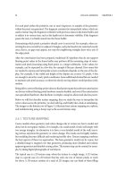
Figure 9.2: Example of combining a texture map into the untextured fragment color in proportion to the texture alpha
channel. The resulting color is C
p
∗ (1 −A
t
) + C
t
∗ A
t
, where C
p
is the untextured color, and C
t
and A
t
are the color and alpha
of the texture map.
GL_REPLACE simply copies Arg0.
GL_MODULATE multiplies two arguments as Arg0 ∗ Arg1.
GL_ADD adds them up as Arg0 + Arg1, while
GL_ADD_SIGNED treats Arg1 as a signed value in [−0.5, 0.5]: Arg0 + Arg1 − 0.5.
GL_INTERPOLATE linearly interpolates two inputs using the third: Arg0∗Arg2+Arg1 ∗
(1 − Arg2) .
GL_SUBTRACT subtracts the second from the first Arg0 − Arg1.
Additionally, GL_DOT3_RGB and GL_DOT3_RGBA can be used only for RGB; they cal-
culate a dot product between the two argument colors as 4 ∗ (s
r
+ s
g
+ s
b
),wheres
r
is
defined as (Arg0
r
− 0.5) ∗ (Arg1
r
− 0.5) and s
g
and s
b
are defined in a similar way. The
resulting scalar value is copied either to the RGB or RGBA of the output. To illustrate
how the texture combiners are used, we give an example that blends a texture map into
the triangle color based on the alpha channel of the texture map. Figure 9.2 illustrates the
combiner setup for this operation. The combiner functions are set as follows:
glTexEnvi( GL_TEXTURE_ENV, GL_COMBINE_RGB, GL_INTERPOLATE );
glTexEnvi( GL_TEXTURE_ENV, GL_COMBINE_ALPHA, GL_REPLACE );
The arguments can be taken from the filtered texture color (GL_TEXTURE), untextured
fragment color (GL_PRIMARY_COLOR), user-specifiedconstant color (GL_CONSTANT,
specified using GL_TEXTURE_ENV_COLOR), or the output color from the previous tex-
ture unit (GL_PREVIOUS). In the example above, GL_INTERPOLATE takes three argu-
ments while GL_REPLACE takes only one. They could be specified with
glTexEnvi( GL_TEXTURE_ENV, GL_SOURCE0_RGB, GL_PRIMARY_COLOR );
glTexEnvi( GL_TEXTURE_ENV, GL_SOURCE1_RGB, GL_TEXTURE );
glTexEnvi( GL_TEXTURE_ENV, GL_SOURCE2_RGB, GL_TEXTURE );
glTexEnvi( GL_TEXTURE_ENV, GL_SOURCE0_ALPHA, GL_PRIMARY_COLOR );
SECTION 9.2 TEXTURE MAPPING 209
Finally, you need to specify whether you want to use the RGB or alpha as input for the
RGB part (for alpha you can only use the alpha component), and these operands can be
either taken as is (arg), or inverted (1 − arg), before being passed to the function.
glTexEnvi( GL_TEXTURE_ENV, GL_OPERAND0_RGB, GL_SRC_COLOR );
glTexEnvi( GL_TEXTURE_ENV, GL_OPERAND1_RGB, GL_SRC_COLOR );
glTexEnvi( GL_TEXTURE_ENV, GL_OPERAND2_RGB, GL_ONE_MINUS_SRC_ALPHA );
glTexEnvi( GL_TEXTURE_ENV, GL_OPERAND0_ALPHA, GL_SRC_ALPHA );
9.2.8 POINT SPRITE TEXTURING
Point sprites are another feature introduced in OpenGL ES 1.1. Many natural phenomena
such as fire or smoke can be emulated by overlaying several copies of textures depicting
flames or smoke puffs. Using quads (quadrangles made of pairs of triangles) to place the
textures is inefficient as four vertices have to be transformed for each quad. It is much
more efficient to use a single point for each sprite instead, to specify the point size, and
paste the texture image across the point.Howe ver, normal points have only a single texture
coordinate which is shared by every fragment on the point. With point sprites you can
generate texture coordinates so they are interpolated across the point. If you call
glEnable( GL_POINT_SPRITE_OES );
glTexEnvi( GL_POINT_SPRITE_OES, COORD_REPLACE_OES, GL_TRUE );
the antialiasing mode of the point is ignored, the point is treated as a screen-aligned
square, and texture coordinates are interpolated across the point so that the upper left
corner has coordinates (0,0) while the lower right corner has coordinates (1,1). That is,
the t-coordinate direction is the reverse of the usual OpenGL convention. Note also that
you have to enable the texture coordinate interpolation separately for each texturing unit.
To disable the interpolation of a unit simply call the function with GL_FALSE. Other
features of texture mapping work exactly the same way as triangles.
9.2.9 IMPLEMENTATION DIFFERENCES
Some features of texture mapping are left optional. For example, the OpenGL ES
specification does not require an implementation to perform the texture coordinate
interpolation in a perspectively correct fashion. Although hardware implementations
are likely to handle this correctly, software implementations often use a much cheaper
screen-space linear interpolation instead. Some of them support both perspective
correct and linear interpolation, and allow choosing between them using glHint
(see Section 10.3).
In a similar fashion, some implementations may only choose the closest mipmap
level instead of interpolating between them, even if the filtering mode asks for it.
210 OPENGL ES RASTERIZATION AND FRAGMENT PROCESSING CHAPTER 9
The effects of auto-mipmap generation of OpenGL ES 1.1 may also vary across
implementations.
Finally, the OpenGL ES specification does not require that the division of the texture
coordinates’ s and t components by the q component is performed separately at each pixel.
Instead, an implementation may do the division by q at vertices, and then interpolate the
coordinates.
9.3 FOG
The next step after texture mapping is fog generation. Fog is used to simulate aerial
perspective, and to make more distant objects fade into a constant color. A detailed
description of fog functions and their parameters can be found in Section 3.4.4. Frag-
ments are blended with a constant fog color ; the blending factor is based on the distance
to the viewer and the current fog mode. Although the fog distance computation is con-
ceptually performed as a part of the fragment-processing pipeline, implementations often
compute the fog values for the vertices of a primitive and then interpolate them. The
quality of the fog computation may be controlled with glHint (see Section 10.3).
The fog color is specified with
void glFog{fx}v(GL_FOG_COLOR, const T * params)
where params points to an RGBA color. Other parameters are set by calling
void glFog{fx}(GLenum pname, T param)
With pname GL_FOG_MODE you can select between params GL_EXP (default),
GL_LINEAR, and GL_EXP2. Further pname GL_FOG_DENSITY applies for the expo-
nential modes, and pnames GL_FOG_START and GL_FOG_END set the start and end
distances for the linear mode.
By default fog is turned off. It can be enabled by calling glEnable( GL_FOG ).
The following example shows how fog is used. As you can see in Figure 3.20, with these
values the GL_LINEAR and GL_EXP2 modes behave in a similar manner, but GL_EXP2
provides a smoother transition.
static const GLfloat bluish_fog[4] = { .5f, .5f, .8f, 1.f };
glEnable( GL_FOG )
glHint( GL_FOG_HINT, GL_DONT_CARE );
glFogfv( GL_FOG_COLOR, bluish_fog );
if( linear )
{
glFogf( GL_FOG_MODE, GL_LINEAR );
glFogf( GL_FOG_START, 20.0f );
glFogf( GL_FOG_END, 70.0f );
}
SECTION 9.4 ANTIALIASING 211
else
{
glFogf( GL_FOG_MODE, GL_EXP2 );
glFogf( GL_FOG_DENSITY, 0.02f );
}
/* draw the object */
glDisable( GL_FOG );
Note that once you enable fog, it is applied to almost every operation, and even if you do
not see much effect (depending on the mode and values you set), you pay the penalty of
the increased processing load. Do not forget to disable the fog when you do not need it
any more.
9.4 ANTIALIASING
There are two basic ways for performing antialiasing in OpenGL ES: edge antialiasing,
which is supported for lines and points, and multisampling, which supports all primitives.
It is also possible to implement antialiasing by combining other OpenGL ES features.
9.4.1 EDGE ANTIALIASING
OpenGL ES supports edge antialiasing for line and point primitives. This means that a
partial pixel coverage percentage is computed for all fragments, and the alpha value of the
fragment is then modulated by the coverage percentage. To create the desired antialiasing
effect, blending must be enabled.
There are some problems with edge antialiasing, however. First, there are no quality
guarantees. There are so many possible ways to implement edge antialiasing that a precise
specification would preclude many feasible approaches. Therefore you do not know how
the antialiasing is implemented; some implementations may even choose to ignore the
request for antialiasing. An even greater problem is that the results depend on the render-
ing order. Say you first render white lines on a blue background. Some of the edge pixels
are going to get a color which is a mix of white and blue. Now if you draw something that
is yellow that is farther from the camera than your white line, but closer than the blue
background, the result can be pretty ugly. Instead of the white line blending smoothly to
the yellow background, many of the boundar y pixels have traces of blue.
The advantage is that since an implementation can precalculate analytically how much
the line covers each pixel, this method can give much higher quality and more efficient
line and point antialiasing than, for example, multisampling. However, for best results the
lines and primitives should be sorted by depth, and drawn in a back-to-front order after
all other parts of the scene have already been drawn.
Edge antialiasing complicates the triangle rasterization rules, and traditionally edge
antialiasing has not been used much for triangles. Therefore OpenGL ES supports it
212 OPENGL ES RASTERIZATION AND FRAGMENT PROCESSING CHAPTER 9
only for points and lines, which makes it relatively straightforward to implement. It is
enabled by calling glEnable with the arguments GL_LINE_SMOOTH or GL_POINT_
SMOOTH.
9.4.2 MULTISAMPLING
Some OpenGL ES implementations support multisampling, an antialiasing mechanism
where each pixel is represented by multiple samples which are combined together at
the end of the frame. This is a somewhat expensive feature, and likely to be found
only in hardware implementations. Multisampling can be enabled or disabled using the
token GL_MULTISAMPLE, and by default it is enabled. Basic multisampling is that easy.
However, you have to make sure that your EGL configuration supports multisampling
(see Chapter 11).
The advantage of multisampling is that it is easy to use: unlike edge antialiasing, it does
not require sorting the objects, and blending does not have to be enabled. The disadvan-
tage is the cost of implementation complexity, and higher use of computation resources.
Depending on the implementation it may or may not execute at the same speed as single-
sampled render ing. The quality of antialiasing depends on the number of samples. Even
on mobile hardware engines the number is not likely to be very high: typically two or four
samples per pixel are supported.
In order to find out whether multisampling is supported by the currently active EGL sur-
face, query the value of GL_SAMPLE_ BUFFERS: here 1 means supported, 0 indicates
not supported. GL_SAMPLES then tells how many samples per pixel are stored. You can-
not usually tur n multisampling on or off per primitive; it should be either enabled or
disabled for the whole rendering pass.
Blending with multisampling
If multisampling is supported, you can use it for a fast approximation to simple blending.
However, beware: on some implementations the overhead of multisampling may be much
bigger than that of blending, so this trick may also slow you down.
The idea is that if some of the samples come from one object and others come from
another, and the samples are then averaged, we get a reasonable approximation of real
blending. For example, if you want to blend two objects 50–50, and your multisampling
system takes 4 samples, instead of rendering the 4 samples twice, and reading pixel values
from the frame buffer to do the blending, you only need to render 2 samples twice and skip
frame buffer reads and blending, resulting in much more than 2 times the performance
increase.
The first approach is to use the alpha values to determine the number of samples to
be generated: low alpha means fewer samples. This is enabled with glEnable
( GL_ SAMPLE_ALPHA_TO_MASK ). In most cases you can now simply ignore the
SECTION 9.4 ANTIALIASING 213
alpha values, as blending is done by the multisampling machinery, but in case you do
care (you have an RGBA frame buffer instead of RGB, or blending has been enabled), as
you take fewer samples, the alpha of those samples should set to 1.0. For this effect call
glEnable ( GL_SAMPLE_ALPHA_TO_ONE ).
The second possibility i s to not use alpha, but to define the sample coverage value directly.
For this you enable GL_SAMPLE_MASK and use
void glSampleCoverage(GLclampf value, GLboolean invert)
void glSampleCoveragex(GLclampx value, GLboolean invert)
where the value parameter tells the percentage of the samples that a “frag ment mask”
selects to pass if invert is false. If invert is true, the samples that would have passed are
killed, and the samples that would have been killed will pass. For example, the following
code would take 75% of thesamples from the first object, and 25% from the second object,
allowing a faster way to blend, for example, two different level-of-detail versions of the
same object.
glEnable( GL_SAMPLE_MASK );
glSampleCoverage( 0.75f, GL_TRUE );
/* here draw object 1 */
glSampleCoverage( 0.75f, GL_FALSE );
/* draw object 2 */
glDisable( GL_SAMPLE_MASK );
This guarantees that the objects get different samples. So if every pixel gets 4 samples, 3
of them would sample object 1, and the last one would sample object 2.
9.4.3 OTHER ANTIALIASING APPROACHES
It is possible to do antialiasing by using feathered RGBA texture maps. Feathering means
that the boundaries are faded, pixels closer to the boundary get progressively smaller alpha
value, and beyond the boundaries the alpha values are zero. Like edge antialiasing, blend-
ing must be enabled for this approach.
The best alpha mask is obtained by rendering the image at a much higher resolution than
the final image, reading it from the server to the client, running a client-side program that
filters the image down [GW02], and redrawing using the filtered image. This approach,
however, is too slow for real-time interactive applications, but can give high-quality results
for still image rendering. A faster but perhaps lower-quality version of this could render
the image directly into a texture map in twice the resolution of the desired final image,
carefully set the texture coordinates so that pixel centers map between the texels, and use
bilinear filtering so that the hardware can do the filtering. This works much faster since
the image doesn’t have to be fetched from the server (GPU) to the client (CPU), but the
whole processing is done at the server.