3D Graphics with OpenGL ES and M3G- P36 ppsx
Bạn đang xem bản rút gọn của tài liệu. Xem và tải ngay bản đầy đủ của tài liệu tại đây (177.23 KB, 10 trang )
334 LOW-LEVEL MODELING IN M3G CHAPTER 14
If the alpha test passes, the depth test then compares the depth value of the fragment
with the depth buffer at the screen location of the fragment. If the depth test passes,
the fragment will be wr itten into the color and depth buffers. Depth testing in M3G is
also simplified from OpenGL ES so that the test is hard coded to “less than or equal”
(GL_LEQUAL). That is, fragments farther away than the existing depth buffer value
are discarded. It is, however, possible to disable the depth test entirely with
setDepthTestEnable(false). Pixels in the frame buffer can then be overwritten
even if they were closer to the camera than the fragments being drawn.
Prior to depth testing, you can optionally add an offset value to all fragment depth
values, similarly to glPolygonOffset shown in Section 9.5.4. This helps solve z-
fighting problems that you may encounter with multi-pass rendering algorithms. The
offset can be set with setDepthOffset(float factor, float units). Here, factor is
a multiplier for the maximum depth gradient and units the number of smallest resolvable
depth buffer units to add. For example:
myCompositingMode.setDepthOffset( — 1.0f, — 1.0f);
brings your geometry closer to the camera by an amount equal to one depth buffer unit
plus the largest depth difference between two adjacent pixels in a triangle. The depth offset
is constant for each individual polygon. For more details, see Section 3.5.1.
All fragments that pass the depth test are written to both the color buffer and the
depth buffer by default, but you can disable wr iting to either if you need to. Depth
buffer writes are controlled with setDepthWriteEnable. Note that disabling depth
writes does not disable the depth test, and vice versa. Controlling color buffer writes
is split between setColorWriteEnable and setAlphaWriteEnable.The
RGB channels are lumped together and cannot be individually disabled—the equiv-
alent OpenGL ES call would be glColorMask(colorWrite, colorWrite,
colorWrite, alphaWrite).
Performance tip: Disabling color writes or alpha writes can force certain hardware
implementations into hugely expensive workarounds. If your frame rate is much less
than you would expect, first make sure that all objects in the scene have alpha wr ites
enabled. Note that this does not concern depth writes.
Blending
Color and alpha channels can be blended with the existing color buffer pixels in a number
of ways. To reduce implementation complexity, M3G simplifies the blending arithmetic
somewhat from OpenGL ES, exposing a predefined set of blending modes rather than
independent source and destination operands—this is another restriction that nowadays
exists mostly for historical reasons. The blending mode is set with setBlending, and
the available modes are summarized in Table 14.3. The default value, REPLACE,doesnot
perform blending but overwrites the existing pixels. ALPHA is traditional alpha blend-
ing, where the fragment alpha value controls the amount of fragment color blended with
SECTION 14.2 ADDING COLOR AND LIGHT: Appearance 335
the color buffer—1.0 results in pure fr a gment color, 0.5 in a 50:50 mix, and so on. It
is most often used for per-pixel transparency and translucency. ALPHA_ADD adds the
alpha-weighted fragment color to the color buffer instead of blending. This is good for
additive light effects such as lens flares. MODULATE and MODULATE_X2 multiply the
fragment and color buffer colors to produce the final color, with the latter multiplying the
end result by two (the result is still clamped before writing to the depth buffer, though).
A common use case for these is light mapping, where the light map is rendered first and
modulated with a detail texture in a second pass.
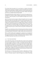
Example: separate specular pass
Let us illustrate multi-pass rendering with an example that renders a separate specular
pass on top of textured geometry, with the level of specularity additionally controlled by
the alpha channel of the texture. Figure 14.2 demonstrates this technique. Assuming that
Table 14.3: The blending modes supported in M3G. C
s
is the incoming fragment color, A
s
is the
fragment alpha, and C
d
is the color in the color buffer.
Mode Function
ALPHA C
d
= C
s
A
s
+ C
d
(1 − A
s
)
ALPHA_ADD C
d
= C
d
+ C
s
A
s
MODULATE C
d
= C
s
C
d
MODULATE_X2 C
d
= 2C
s
C
d
REPLACE C
d
= C
s
Figure 14.2: Demonstrating a separate specular pass with controllable degree of glossiness. The
per-pixel gloss factors can be stored in the alpha channel of the base texture map. (Image copyright
c
AMD.) (See the color plate.)
336 LOW-LEVEL MODELING IN M3G CHAPTER 14
youhaveyourtextureinanRGBAjavax.microedition.lcdui.Image object
myTextureImage, you need to construct two Appearance objects:
// First pass applies diffuse lighting modulated by the texture
Appearance diffusePass = new Appearance();
Image2D myTextureColor = new Image2D(Image2D.RGB, myTextureImage);
Texture2D diffuseTexture = new Texture2D(myTextureColor);
diffuseTexture.setFiltering(Texture2D.FILTER_NEAREST,
Texture2D.FILTER_NEAREST);
diffusePass.setTexture(0, diffuseTexture);
Material diffuseMaterial = new Material();
diffuseMaterial.setColor(Material.AMBIENT|Material.DIFFUSE,
0xFFFFFFFF);
diffusePass.setMaterial(diffuseMaterial);
// Second pass adds specular lighting on top of the previous pass
Appearance specularPass = new Appearance();
Image2D myTextureGloss = new Image2D(Image2D.ALPHA, myTextureImage);
Texture2D specularTexture = new Texture2D(myTextureGloss);
specularTexture.setFiltering(Texture2D.FILTER_NEAREST,
Texture2D.FILTER_NEAREST);
specularTexture.setBlending(Texture2D.FUNC_REPLACE);
specularPass.setTexture(0, specularTexture);
Material specularMaterial = new Material();
specularMaterial.setColor(Material.AMBIENT|Material.DIFFUSE, 0);
specularMaterial.setColor(Material.SPECULAR, 0xFFFFFF);
specularMaterial.setShininess(50.f);
specularPass.setMaterial(specularMaterial);
CompositingMode additiveAlphaBlend = new CompositingMode();
additiveAlphaBlend.setBlending(CompositingMode.ALPHA_ADD);
Now, when you render your geometry first with diffusePass and then
specularPass, you get specular highlights over your diffuse texturing based on the
per-pixel alpha value. You may also want to disable the depth writes on the second pass,
as the same depth values are already written in the first pass.
Pitfall: Blending has no effect on depth writes. If you have an alpha-blended surface
and you want anything from behind it to show through, you must order your rendering
carefully so that the blended geomet ry is rendered last. You may also be able to just use
the alpha test if your transparency boundaries are shar p enough. Note that transparent
parts may also overlap w ithin the same object.
We have now reached the end of the fragment pipeline and our fragments have been
written to the frame buffer. With its combination of blending modes and write masks,
SECTION 14.3 LIGHTS AND CAMERA 337
CompositingMode can be used to build more complex multi-pass rendering effects
than shown here. With the layer mechanism in Appearance, all of those can also be
incorporated into M3G scene graphs, as we shall discuss in Chapter 15.
Now, you can play around with the various Appearance settings we have constructed
so far in the example. Make note of how they affect the rendering results, but also be aware
of the fact that, for example, the CompositingMode settings are greatly dependent on
what you are compositing with and in which order, and Material really needs some
light to work properly.
14.3 LIGHTS AND CAMERA
So far, we have hinted at lighting and cameras, and the Light and Camera classes,
without going into much detail. Let us now take a closer look at how to manipulate the
camera from our examples, and how to use the built-in lighting functionality.
14.3.1 Camera
Similarly to a real-life camera, through Camera you can control your projection and
viewpoint. Camera can be used in both scene graphs and immediate mode.
Using the Camera class is actually rather simple. First, create your camera:
myCamera = new Camera();
This gives you a camera with a default projection—an identity projection matrix, to be
more precise—as we have seen in the examples so far. The default projection maps your
3D coordinates onto the screen so that X at −1 maps to the left and +1 to the right edge
of the screen; Y at −1 to the bottom and +1 to the top; and only objects within Z range
from −1 at the near and +1 at the far clipping plane are visible. There is no perspective in
this projection; in other words, it is a parallel projection.
Projections
To keep the parallel projection, but change the parameters, call:
setParallel(float fovy, float aspectRatio, float near, float far)
Here, fovy is the height of the view volume in camera coordinates, aspectRatio is the ratio
of width to height, and near and far give the distances to the near and far clipping planes.
By using a negative distance, you can place one or both of the planes behind the camera
location. Note that you can also specify the clipping planes in arbitrary order—if far is
less than near, then objects farther down the Z axis will appear to be closer.
338 LOW-LEVEL MODELING IN M3G CHAPTER 14
For a perspective projection, call:
setPerspective(float fovy, float aspectRatio, float near, float far)
Again, fovy gives the vertical size of the viewing volume, but as an angle of anything
between ]0, 180[ degrees. aspectRatio is the ratio of viewport width to viewport height,
and near and far give the clipping distances. With perspective projection, the distances
must be positive, and near must be less than far.
Finally, if you need a more customized projection, you can call:
setGeneric(Transform transform)
This lets you handle special cases such as off-center projections and infinitely far clipping
planes, should you need them.
Camera transformations
The camera, by default, looks from the origin in the direction of the negative Z axis. This
is boring, so you can supply a camera transformation when setting the camera to your
Graphics3D for immediate mode rendering:
Graphics3D g3d = Graphics3D.getInstance();
g3d.setCamera(myCamera, myCameraTransform);
This makes myCamera the camera to use for subsequent immediate mode rendering,
after transforming it with the Transform object myCameraTransform. You can
also keep calling this to just update the camera transformation as necessary. Your
Camera is transformed exactly like light sources and polygon meshes. You can also use
a null Transform to indicate identity.
Let us illustrate how you could position and aim your camera based on your own position,
yaw, and pitch variables, as well as set a desired maximum field of view from another
variable. We assume that myCanvas points to your MIDP Canvas object:
Camera myCamera = new Camera();
Transform cameraTransform = new Transform();
cameraTransform.postTranslate(cameraX, cameraY, cameraZ);
cameraTransform.postRotate(cameraYaw, 0, — 1.f, 0);
cameraTransform.postRotate(cameraPitch, 1.f, 0, 0);
g3d.setCamera(myCamera, cameraTransform);
float width = myCanvas.getWidth();
float height = myCanvas.getHeight();
if (height >= width) {
myCamera.setPerspective(cameraFOV, width/height, 1.0f, 100.0f);
}
SECTION 14.3 LIGHTS AND CAMERA 339
else {
myCamera.setPerspective(cameraFOV*height/width, width/height,
1.0f, 100.0f);
}
Note that this will not give you an exactly fixed field of view on a wide display—that
would require using the atan function, which is not available in the Java ME math pack-
age. Barring extreme cases, though, the accuracy of the example above should suffice for
normal use.
Pitfall: Make sure that your scene is in front of your camera. It is easy to get confused
with the various coordinate systems and to lose track of where everything needs to be
in relation to the camera. In particular, do remember that the positive Z axis points
out of the screen, i.e., behind the camera. To make sure that your camera is working,
you can always revert back to an identity camera transformation and try placing your
objects at a suitable distance away on the negative Z axis. If this makes them visible,
you probably have moved something or rotated the camera in the wrong direction.
Note that as the camera is conceptually the eye that everything is rendered through, the
renderer actually needs to transform e verything else relative to the camera as discussed in
Section 2.4. For that purpose, the camera transformation is not applied to the camera,
instead the inverse of that transformation is applied to everything else to move the world
into the camera’s coordinate system, the eye coordinates. If the camera transformation
is not invertible, your whole world vanishes into a singularity before the camera has a
chance to see it. But if you simply place your camera in the 3D world like any other object,
everything works just fine.
In summary, the modelview transformation in M3G is really composed of two parts:
model, which you supply with each rendered mesh, and view, which comes from the
camera transformation. This is then combined with the projection matrix to give the full
vertex transformation to normalized device coordinates
T
NDC
= PC
−1
M
(14.2)
where P is the projection matrix, C the camera transformation, and M the modeling
transformation.
14.3.2 Light
Lights in M3G are represented by the Light class. It is also a scene graph node, but
serves a second function as an immediate mode light source. We will concentrate on the
general functionality here, and revisit the scene graph related aspects of lighting in the
next chapter.
340 LOW-LEVEL MODELING IN M3G CHAPTER 14
Similarly to Material, Light is a very straightforward wrapper for equivalent parts of
the OpenGL lighting model. Some of the details are arranged differently in the interest of
user-friendliness and to make it more obvious how things work, and some simplifications
have been made to the capabilities of individual light sources. However, using multiple
light sources, you can get the same functionality with both APIs, with one exception:
M3G only lets you control the specular and diffuse lighting contributions separately at
material level, not in light sources.
Let us begin by creating a light source:
myLight = new Light();
This creates a directional light that is white. Directional and spot lights in M3G always
shine in the direction of the negative Z axis in their local coordinate system. The light
direction is changed with transformations applied to the light. Similarly, the default posi-
tion of the light source at the origin can only be modified through transformations.
Managing lights
To use the light for immediate mode rendering, we have to add it to the Graphics3D
object:
Transform myLightTransform = new Transform();
myLightTransform.postRotate(90.0f, — 1.0f, 0, 0);
g3d.addLight(myLight, myLightTransform);
The Graphics3D.addLight function inserts a new light source into the
Graphics3D object. You can insert as many lights as you want, and these lights
will be used for lighting in subsequent immediate mode rendering. However, only a
fixed maximum number of lights will be used to light any single mesh—this value can
be queried using Graphics3D.getProperties. If you exceed this limit, M3G will
automatically select a subset of the light sources currently set to Graphics3D.
Pitfall: Basically, there is no guarantee that a particular M3G implementation will select
a good subset of lights if you have set a large number of them. For best results, select the
most important light sources yourself, and only add those to Graphics3D, or use the
scoping functionality (Section 15.6.2) to control light selection.
The Transform object, myLightTransform, gives the transformation from the
local coordinate system of the light source to world coordinates—in other words, lights
are transformed exactly like polygon meshes. You can also specify null to indicate an
identity transformation. In our example, the light will be shining down the negative Y axis
after the transformation. The transformation is copied in, so any changes made to it after
calling Graphics3D.addLight have no effect on the light. The transformation of the
SECTION 14.3 LIGHTS AND CAMERA 341
Light node itself is also ignored when used for immediate mode lighting, but changes
to other light source parameters do, however, affect subsequent rendering.
In addition to addLight, Graphics3D also offers setLight, which you can use
to modify the lights added with addLight. addLight returns an integer index for
each light you add, and you can pass this index to setLight to set a new light source
or new light transformation for that slot. You can also remove a light by setting its slot to
null. You can remove all lights by calling Graphics3D.resetLights.
Types of light sources
The type of light source is selected via setMode(int mode). The default, as we have
seen, is DIRECTIONAL for a directional light. AMBIENT makes the light shine equally
from all directions, whereas OMNI makes the light shine from its position toward
all directions. SPOT adds directionality and the spot cone parameters. These are set
using setSpotAngle(float angle) and setSpotExponent(float exponent).
Performance tip: The different light types have different runtime performance costs.
AMBIENT is virtually free, and DIRECTIONAL is cheap enough that it can often be
used with software-only M3G implementations. OMNI and especially SPOT are con-
siderably more expensive, so their use should be limited to where absolutely necessar y.
Regardless of the light type, you can set the light color through setColor
using the familiar hexadecimal 0xAARRGGBB color notation. For example,
myLight.setColor(0x00FF3311) gives myLight a strong red tint. The inten-
sity of the light is set separately in floating point using the setIntensity function—
this lets you animate either one independently of the other. Multiplying the color and
intensity gives the light value used in the lighting computations. Note that “overbright”
and even negative intensities are quite acceptable. As a simplification from the OpenGL
model, the same color and intensity are used for both specular and diffuse lighting.
Finally, you can specify attenuation parameters for OMNI and SPOT lights through
setAttenuation(float constant, float linear, float quadratic). For AMBIENT
and DIRECTIONAL lights, attenuation has no effect. For a detailed explanation of the
attenuation parameters, as well as other lighting parameters, refer to Section 3.2.
Performance tip: In general, lighting is rather complex and should only be used when
you really need it. Features like spot lights and attenuation are particularly expensive
performance-wise.
For static scenes, you will always get better results by baking the lighting information
into your vertex colors or texture maps. For dynamic scenes, you can use texture maps
342 LOW-LEVEL MODELING IN M3G CHAPTER 14
and texture transformations to very cheaply simulate diffuse lighting and even add some
reflections.
Be especially warned that some of the early mobile graphics hardware may have
hardware-accelerated transformations, but run the lig hting pipeline in software. This
means that using the traditional lighting can completely kill your otherwise good ren-
dering performance—the Sony Ericsson W900i is one example you might encounter in
the real world.
Example
Let us conclude with an example on setting up lights and materials.
static final int red = 0xFFFF0000;
static final int white = 0xFFFFFFFF;
static final int red_transp = 0x00FF0000;
static final int blueish = 0xFF2066FF;
static final int black = 0;
Graphics3D g3d = Graphics3D.getInstance();
// Create a scene global ambient light
Light ambient = new Light();
ambient.setMode(Light.AMBIENT);
ambient.setColor(red);
ambient.setIntensity(0.2f);
g3d.addLight(ambient, null);
// Create a directional light at the origin, shining in the direction
// of the negative Z axis
Light dirLight = new Light();
dirLight.setMode(Light.DIRECTIONAL);
dirLight.setColor(white);
dirLight.setIntensity(1.0f);
g3d.addLight(dirLight, null);
// Create a spot light close to the origin, aimed diagonally down
// and to the left — — note that in immediate mode, the transformation
// in the Light object is ignored, so we pass it as a separate object
Light spotLight = new Light();
spotLight.setTranslation(5.f, 5.f, 0.f);
spotLight.setOrientation(60.f, — 1.f, 1.f, 0.f);
spotLight.setMode(Light.SPOT);
spotLight.setColor(white);
spotLight.setIntensity(5.0f);
spotLight.setSpotAngle(40.f);
spotLight.setSpotExponent(10.f);
spotLight.setAttenuation(0.f, 1.f, 0.f);
Transform t = new Transform();
spotLight.getCompositeTransform(t);
g3d.addLight(spotLight, t);
SECTION 14.4 2D PRIMITIVES 343
// Create a material to receive the lights
Material material = new Material();
material.setColor(Material.AMBIENT|Material.DIFFUSE, blueish);
material.setColor(Material.SPECULAR, red_transp);
material.setColor(Material.EMISSIVE, black);
material.setShininess(15.f);
14.4 2D PRIMITIVES
In addition to polygon meshes, M3G can also render 2D graphics to some extent. The
Background class allows you to clear the viewport w ith a solid color or an image.
Sprite3D represents a slightly more versatile object, letting you draw a 2D image that
has a 3D position and interacts with the 3D graphics. Both of these can be used in both
immediate and retained mode rendering.
The 2D features were some of the more controversial topics discussed by the M3G
standardization group, with opinions strung between compatibility with the coming
OpenGL ES standard, and enabling proprietary optimizations on software engines that
would not be using hardware acceleration. In the end, the group tried to compromise
between the two camps, which unfortunately meant including some nasty limitations
and special cases in the 2D feature set. It soon turned out, however, that this lean toward
proprietary software engines was largely in vain, as all the major implementations were
moving toward full OpenGL ES compatibility more quickly than anticipated. This left
the possibility for software 2D graphics optimizations mostly unused. Nevertheless, the
2D feature set exists in the API and can be used for the intended purposes, barring a few
loopholes which we will highlight below.
14.4.1 Background
By default, the color buffer is cleared with transparent black and the depth buffer with
the maximum depth value. The color buffer can also be cleared with a given color and
alpha, or with a background image that can be independently scaled, tiled and centered
in the horizontal and vertical directions. The depth buffer can only be cleared with the
maximum depth value of 1.0, or not cleared at all.
Recall that in immediate mode, you need to clear the screen manually. In retained mode,
we will see how the Background object can be associated with your World.
To enable and disable clearing the color and frame buffers and to set the clear color, use
the following methods:
void setColor(int ARGB)
void setColorClearEnable(boolean enable)
void setDepthClearEnable(boolean enable)