The Complete IS-IS Routing Protocol- P10 ppt
Bạn đang xem bản rút gọn của tài liệu. Xem và tải ngay bản đầy đủ của tài liệu tại đây (235.16 KB, 10 trang )
The above example shows a very simple policy. It creates a policy named all-statics under
the policy-options branch of the configuration hierarchy. Next, it defines the match and action
clauses. If the route’s originating protocol is “from” static, then accept that prefix. Note that
in the “then” part no detailed action is actually specified for the prefix. This is largely depend-
ent on which routing protocol has called the policy, and where the policy is applied.
For example, if the policy is applied as an export policy within OSPF:
protocols {
ospf {
export all-statics;
}
}
This means that all prefixes that are installed in the inet.0 routing table and are static
routes (these alone match the policy all-statics) will be redistributed into OSPF
and announced to all OSPF neighbours.
But if the same policy is applied as an export policy within BGP:
protocols {
bgp {
group internal {
export all-statics;
neighbor 172.26.250.2;
neighbor 172.26.244.11;
[ … ]
}
}
}
This means that all the static routes present in the inet.0 table are not announced to all
OSPF neighbors as in the previous example, but only to the BGP peers present in the
peer-group internal. So the ultimate result depends on where the policy is applied.
Policy processing is typically deployed for filtering BGP routes. Generally, IS-IS poli-
cies are simple, one-to-three term policies, which are easily readable. To learn more
about the JUNOS routing policy language and policy processing in general, the Juniper
Networks Book Initiative (JNBI) lists pointers to good books with more detailed elabo-
ration on about policy processing.
3.3.9 Further Documentation
The entire documentation about Juniper Networks Routers is available on the Juniper
Networks public website at Further documentation and
books about JUNOS routing technology is posted at />3.4 Conclusion
Both JUNOS and IOS offer the network operator powerful user interfaces to provision,
troubleshoot and change the network and router configurations. Interestingly, although
Conclusion 77
both IOS and JUNOS) user interfaces are different, there are plenty of common ele-
ments, such as plain-text ASCII configuration files, two working modes (operational
mode and configuration mode), auto-completion of commands, Emacs-style keyboard
sequences, and a rich debugging facility. Experience from training NOC teams has shown
that because of these common elements, an engineer that is used to one router OS can,
after a short learning and introduction phase, pick up the necessary skills to adapt to a new
environment quickly and easily.
78 3. Introduction to the IOS and JUNOS Command Line Interface
4
IS-IS Basics
79
The main challenge for people wanting to learn about IS-IS is that the specifications are
scattered across multiple standardization bodies. There is no single place to look at and
get a quick overview about IS-IS and how it routes the IP protocols. Meanwhile, all the
extensions to the base IS-IS protocol are documented in more than 25 documents, which
makes it difficult for novice users to get a quick overview.
This chapter provides a quick overview of IS-IS. A lot of the topics introduced in this
chapter will be explained in more detail in subsequent chapters. If you just want to get a
quick overview of how IS-IS works all you have to do is read this chapter.
Readers of the basic specification of IS-IS (ISO 10589) will most likely be surprised by
the constant use of OSI jargon that tries to invent an OSI counterpart for every term and
acronym used in IP and the Internet. So reading this often arcane language for under-
standing can be very difficult. Also, there is a lot of extra information contained in the
base specification unrelated to the protocol itself, like implementation details and even
advice on how to code. However, most of this advice is completely outdated and it has
become common to ignore most of the specification text. Once you have developed an
understanding about the jargon and what paragraphs not to read and consider, you will
find that IS-IS is a lean but powerful protocol, easy to use and even simpler to understand.
However, jargon cannot be completely avoided in IS-IS. This chapter also assumes
that readers are familiar with the basic concepts of the OSPF routing protocol and the
terms used in the IP protocol family. At first, there will be translation of OSI jargon to IP
terminology, but later in the book we use the OSI terms, which should become familiar
as the book progresses.
4.1 IS-IS and the OSI Reference Model
IS-IS is very different than other network routing protocols because it runs natively on
Layer 2 of the OSI Reference Model. What does that mean? Unlike the IP routing proto-
cols like RIP, OSPF and BGP, IS-IS does not need valid interface addressing information
to transmit a message. Of course IS-IS needs some information to properly transmit rout-
ing messages, but compared to other IP routing protocols, the IS-IS configuration file is
far smaller.
Running natively on Layer 2 of the OSI Reference Model has another important
aspect, which is suitability for routing multiple protocols. In fact IS-IS is totally agnostic
about what kind of prefixes it transports in its message. Figure 4.1 shows the position of
IS-IS in the networking stack. Here, IS-IS messages are directly encapsulated for an
802.3 Ethernet. And in the message is reachability information from the various network
layer protocols such as IPv4, IPv6 and even IPX. Netware uses a clone of IS-IS called
Netware Link State Routing Protocol (NLSRP), which shares most of the message types
with IS-IS, and it is used for conveying Netware’s IPX reachability information. Figure 4.1
also shows, somewhat surprisingly for those used to IP, that ISO’s Layer 3 protocol, CLNP,
is dependent on IS-IS and not the other way around as it would be with IP and OSPF.
This misconception is common, as we have learned over and over again when giving
IS-IS training classes. Most students think that running CLNP is the prerequisite for run-
ning IS-IS. This belief is reinforced if the students first learn about IS-IS on Cisco’s IOS.
For code legacy reasons, you have to enable CLNS routing first before you can run IS-IS
on IOS platforms. Even for the majority of IOS show commands there is still only the
show clns … syntax instead of show isis …. Therefore most people think that IS-IS
runs over CLNP, even though the contrary is the case. IS-IS is an independent protocol
and CLNP is just one of the many protocol address families it can transport.
IS-IS only understands two interface types: broadcast and point-to-point (p2p) media.
The most common example of broadcast media is of course the family of Ethernet speeds
(10, 100, 1000, 10,000 Mbps). But there are also older technologies like Token Ring, and
FDDI. In recent years there has been increased demand for Resilient Packet Ring (RPR)
technology, which is mostly an FDDI knockoff, but augmented with SONET/SDH head-
ers, which makes the frames transportable using SONET/SDH Time Division Multiplexing
(TDM) equipment. Resilient Packet Rings appear to IS-IS as broadcast media using the
usual LAN 48-bit IEEE MAC addresses. Of all these media types, Ethernet is the most
commonplace by far and is also the only broadcast media type that will be referenced
throughout the book. Figure 4.2 shows how a native IS-IS message is encapsulated in
Ethernet frames. All IS-IS messages are sent to one of the two well-known multicast
MAC addresses 0180:c200:0014 or 0180:c200:0014. On broadcast media such as Ethernet
there are no IS-IS unicast messages. IS-IS wants to make sure that every router con-
nected to the LAN hears all of its messages. The source MAC address is typically the
burned-in-address (BIA) of the sending Ethernet port. Next is the length field, which tells
the receiver how long the entire Ethernet frame will be. The next two bytes indicate the
destination service attachment point (DSAP) and source service attachment point
(SSAP). Each major networking protocol has an SAP code point assigned. The two
SAPs indicate which parts of the system talk to each other. A DSAP of 0xFE and a SSAP
of 0xFE means that an OSI protocol on the sender side wants to talk to an OSI protocol
on the receiver side (oddly, the DSAP and SSAP don’t have to match, but most protocols
80 4. IS-IS Basics
IS-IS common header
OSI Reference Model Layer 2
IP IPXIPv6CLNP
IEEE 802.3
Physical Layer
OSI Reference Model Layer 1
FIGURE 4.1. IS-IS is a true multiprotocol IGP as it runs native on Layer-2
only understand other versions of themselves). The last byte before the common IS-IS
header is the control byte which tells the receiver if the sender desires flow-control at the
Ethernet level. IS-IS does not do flow-control at the MAC level, and turns it off using the
code point value of 3.
For Ethernet there are in general three different methods of encapsulating higher
layer information (packets) inside Ethernet frames. The encapsulation method shown in
Figure 4.2 is called 802.3 or, in Cisco Systems-IOS-speak, SAP encapsulation. There is
also the Ethernet II encapsulation also known as DIX or ARPA encapsulation, which
replaces the length field of the 802.3 encapsulation format with a 16-bit type code.
Assigning all type codes with values greater than 1500 (the limit for the length field)
avoids collisions between code points and valid frame lengths, which must be less than
1518 bytes altogether. The final encapsulation method is called sub-network access proto-
col (SNAP), and is an extension of the IEEE 802.3 encapsulation. The DSAP and SSAP
are set to 0xAA (the “SNAP SAP”) and this indicates that another 5-byte header follows,
which gives the protocols inside more room for type information and eases the allocation
of code points for vendor-proprietary protocols. This is achieved by prepending the
3-byte organizational unit identifier (OUI) that each Ethernet vendor has been assigned
before the 2-byte protocol code point (which is actually the DIX Ethernet type field that
the length field replaced!).
Interestingly, IS-IS never used any other encapsulation than 802.3. So although there
are OSI code points for the two other encapsulation methods (Ethernet II and SNAP)
they have never been widely used for IS-IS. Most IS-IS implementations did not even
accept IS-IS messages with a non-IEEE 802.3 encapsulation style. Today, IEEE 802.3
encapsulation is the only possible Ethernet encapsulation for IS-IS and the two others are
considered to be “illegal”.
IS-IS and the OSI Reference Model 81
Destination MAC Address
0180:c200:0014
or 0180:c200:0015
Bytes
6
6
2
1
1
1
min.: 27
max.: Link MTU-21
Source MAC Address
IEEE 802.3 Length field
IEEE 802.3 DSAP
IEEE 802.3 SSAP
IEEE 802.3 Control
IS-IS common header & TLVs
FCS
0xFE
0xFE
0x03
4
FIGURE 4.2. IS-IS messages are transported over Ethernet using IEEE 820.3 (802.2 LLC) encap-
sulation only
Inside the frame is the native IS-IS message, which can be a minimum of 27 bytes and
at maximum the size of the link MTU size minus 21 bytes. If you do the mathematics,
21 bytes is the sum of the two MAC address, DSAP, SSAP, Control byte fields, plus the
4 bytes of trailing frame check sequence (FCS) at the end of the frame. The link MTU size
varies with the type of Ethernet chipset in use. All Ethernet network interface cards (NICs)
must support at least the standard Ethernet MTU of 1518 bytes (including FCS). However,
there are chipsets around which can generate jumbo frames which generate Ethernet
frames up to 9000 bytes in length. That’s the reason the maximum IS-IS packet length is
dependent on the actual link MTU size and is not a simple number. The maximum
amount of IS-IS information that can be stored in a standard Ethernet Frame is 1518 minus
21, or 1497 bytes. IS-IS must ensure that it does not transmit frames any larger than
that even if it has to fragment the IS-IS message and scatter pieces across several Ethernet
frames (there is no support for fragmentation on the Ethernet level). There is more about
fragmentation and how IS-IS deals with larger than link-MTU-sized packets in Chapter 9.
For point-to-point media there are a variety of encapsulations like PPP, Cisco-HDLC,
Frame Relay and ATM RFC1483/2684 encapsulation. However, the most common
encapsulation is the Point-to-Point-Protocol (PPP), which will be the only one that is
used throughout the book. PPP has been designed to carry multiple network layer proto-
cols. Figure 4.3 shows the PPP model of multiplexing several protocols over a single link.
First, a protocol called the PPP line control protocol (LCP) opens up the circuit and first
negotiates parameters concerning the link. Examples of LCP duties are negotiation of
authentication, compression, three-way handshake etc.
Next, for each network protocol like IP, IPX, IPv6 and OSI, there is a dedicated control
protocol (CP). For instance, the IP Control Protocol (IPCP) assigns an IP address when
dialling in to a service provider’s access server. So the control protocol negotiates per-
network-protocol properties. For encapsulation of IS-IS messages over the point-to-point
circuit, first, the OSICP has to come up successfully. OSICP is a very lightweight protocol,
sometimes not even considered a protocol, more like something along the lines of a cap-
ability announcement like “Hey! I can speak OSI, so you can send me OSI frames if you
want.” Once the control protocol is done, the payload frames are transported using a
pre-protocol assigned code point. Figure 4.4 shows the structure of an IS-IS frame that has
been encapsulated in PPP. The frame simply gets prepended using the OSI code point
0x0023. Minimum frame size (assuming the smallest possible IS-IS message of 27 bytes)
is 27 plus 4 (PPP overhead), or 31 bytes. The biggest frame once again depends on the link
MTU size of the underlying circuit. Typically, SONET/SDH circuits have a maximum
82 4. IS-IS Basics
PPP LCP
PPP IPCP
PPP IP6CP
PPP OSICP
Router A Router B
FIGURE 4.3. Before traffic is transported the OSI control protocol and PPP line control protocol
have to get into opened state
transmission unit of 4474 bytes. By subtracting the PPP overhead (4 bytes) from the 4474
bytes, this results in 4470 being the maximum MTU size on most point-to-point circuits.
IS-IS skipped all the hassle of complicated varieties of encapsulation and interface
models by specifying very clearly in the specification how the format of the final frame
looks. This clearly helped interoperable implementations to exist right from the beginning.
4.2 Areas
OSI structures its network topology in a distinctive way. IS-IS is much more flexible
when it comes down to migrating parts of the network to another routing protocol or
grooming existing ones. The tool to make that happen is called an area.
In the infancy of link-state protocols, the whole network consisted of a single set of
routers that all shared a common database to compute the best paths through the network.
At this time almost everybody working in standardization bodies seemed to be concerned
about the nature of the SPF algorithm and doubted the scaling abilities of link-state routing
protocols in general. In light of the exponential nature of the SPF algorithm, where the
CPU demand seemed to grow infinite, the IS-IS protocol developers made an interest-
ing move.
The idea was to structure a large network in smaller parts called areas. The topologi-
cal horizon of the IS-IS routers becomes smaller to keep the CPU less busy during the
route calculation process. But if a bigger network is split into smaller networks, then a
set of disjoint sub-networks results. In order to connect these islands there need to be
routers that route traffic between the areas. Even if the topological horizon and hence the
computational complexity of the SPF run has been reduced, the network still has to retain
all available reachability information and the routers at the area borders inject that reach-
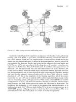
ability information into each other’s areas. Figure 4.5 shows how this is done. The Big
IS-IS network 4711 is split into two areas: Area 47 and Area 11. The computational com-
plexity has been halved; however, in order to ensure full connectivity the router between
Area 47 and Area 11, Router A, summarizes and injects all the reachable prefixes from
Area 47 to Area 11, and Router B does the reverse. The IP prefixes in this example
assume the reader is familiar with IP addressing and style. However, the transported pre-
fixes are not restricted to just IP, they could be from any address family. Router A and
Router B summarize their local prefixes and advertise them into the other areas. Router A
sends a summary route 172.16/16 representing the local 172.16.X/24 prefixes (including
Areas 83
Bytes
2
2
min.: 31
max.: Link MTU-4
PPP Header
PPP OSI Protocol
IS-IS common header & TLVs
0xFF03
0x0023
FIGURE
4.4. IS-IS over PPP
its own) towards Area 11 and Router B sends a summary route 172.17/16, resulting from
all the local 172.17.X/24 prefixes in Area 11, to Area 47.
The effect is remarkable – today, 1000–2000 routers in a single area are said to repre-
sent the upper boundary of IS-IS. With support of areas the network can grow to arbitrary
size – today the biggest multi-area networks have about 12,000–15,000 routers. The
authors do not endorse these optimistic area numbers, since a lot, is dependent on other
factors than just the raw number of routers. But the above example should make it clear
that by splitting up a large network into several smaller areas, the result is a network that
is much more scalable than with a single-area approach.
Note that in Figure 4.5 Router A and Router B are members of their assigned areas and
are not part of both areas. To those familiar with OSPF, this may seem odd at first, but IS-IS
makes a distinction between area boundaries and the routing hierarchy levels that result.
Decoupling area boundaries from routing hierarchy levels allows greater flexibility for
migrating, joining, or splitting areas. The tool in IS-IS for creating routing hierarchies is
called a level.
84 4. IS-IS Basics
Area 11Area 47
Area 4711
172.16.4/24
Router A
Router B
172.17.7/24
172.17.8/24
172.17.9/24
172.16.1/24
172.16.2/24
172.16.3/24
172.16.1/24
172.16.2/24
172.16.3/24
172.17.7/24
172.17.8/24
172.17.9/24
172.16.4/24
172.17.6/24
172.16/16
172.17/16
FIGURE 4.5. For a working hierarchical routing, the border routers need to summarize the reacha-
bility information of their areas and inject it to the other areas
4.3 Levels
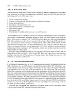
To understand why the introduction of an area leads to the idea of a level scheme to
denote routing hierarchies, compare the OSPF routing hierarchy with IS-IS. Figure 4.6
shows the differences between OSPF areas and IS-IS areas. In OSPF, the area border
router (ABR) has two interfaces in each area: one interface in Area 51 and another inter-
face in Area 0. One could say the demarcation line between the two areas is through the
“middle” of the ABR. In IS-IS, it is the other way around: there is not a special ABR that
sits between two areas. Routers stay in their assigned areas. One could say here that the
demarcation line is through the middle on the link between the routers in two areas.
How can two routers ever exchange routing information if they are in two entirely sep-
arate areas? In OSPF, the Area-ID of the routers at each end of the link has to match, other-
wise no adjacency will form between the two routers. An adjacency is a kind of promise
that a pair of routers can mutually exchange traffic. More about adjacencies and how they
are formed is found in Chapter 5.
In IS-IS, the Area-ID does not necessarily have to match for an adjacency to come up.
The reason is that for every link that runs IS-IS, there is a little tag indicating the kind of
topology level to which the link should belong. Each router in an IS-IS network builds
two different topologies: the Level-1 topology and the Level-2 topology. Figure 4.7
shows this. Each link carries one of three possible tags: L1, L2 or L1L2, which tells the
router in which topology level the link wishes to participate: Level-1, Level-2, or both.
Based on the level tags shown in Figure 4.7, the resulting topology is illustrated in
Figure 4.8. There are links in the figure that have non-matching Area-IDs on both ends
of the links (like the L2-only links between Areas 47, 11 and 12). However, Level-2 adja-
cencies are a bit kludgy by nature. All routers participating in the Level-1 topology do have
to share their Area-IDs; otherwise no adjacencies will form up, just as in OSPF. But when
a link is configured for Level-2, a matching Area-ID is not important as far as adjacency
formation is concerned. An adjacency will form no matter if the Area-IDs match or not.
For the IS-IS Level-2 backbone, the only constraint is that the Level-2 topology must be
continguous, and no Level-2 routers are isolated from any others.
Levels 85
Area 51
Area 0
Demarcation line
Area 11
Area 47
Area 52
OSPF IS-IS
FIGURE 4.6. OSPF vs. IS-IS topological boundaries
4.3.1 IS-IS Routing Hierarchy Rule
Routers that share the same Area-IDs determine the Level-1 topology, and Routers that share a
continguous set of Level-2 circuits determine the Level-2 topology
The interesting thing here is that a link can participate in both (Level-1 and Level-2)
topologies. And having a (logical) extra link handy is useful and helps to avoid
86 4. IS-IS Basics
Area 11
Area 12
Area 47
L1L2
L2
L1L2
L2
L1L2
L2
L1
L1
L1
L1
L1
L1
L1L1
FIGURE 4.7. The level information is configured on a per interface basis; three tags are possible per
circuit – L1, L2 and L1L2
Area 11
Area 12
Area 47
Level 2 Topology
Level 1 Topology
FIGURE 4.8. The resulting Level-1 and Level-2 topology based on Figure 4.7