The Complete IS-IS Routing Protocol- P20 ppt
Bạn đang xem bản rút gọn của tài liệu. Xem và tải ngay bản đầy đủ của tài liệu tại đây (150.83 KB, 10 trang )
JUNOS software configuration
hannes@Frankfurt> show configuration
[… ]
protocols {
isis {
interface at-4/0/0.100 {
lsp-interval 50;
}
}
}
[… ]
LSP throttling by use of the lsp-interval command is a powerful mechanism to
control the flooding pace to neighbouring routers in order to not overload them. There is
another issue that has not yet been discussed: control traffic (LSP and related packets)
may “push back” the user traffic (information packets) because control traffic always has
precedence in terms of scheduling on the router interface cards. Unfortunately, the con-
trol traffic transmission rate does not get lower on low-bandwidth interfaces such as DS0
or fractional T1/E1 line – control traffic stays the same. You can easily imagine that on a
low-bandwidth circuit transmitting 30 full-MTU sized packets does not leave much
room for other types of packets. So it would be nice if there were a way to tell the router
just to utilize a certain percentage of the interface bandwidth for control traffic. In IOS,
you can configure the bandwidth <bw> statement on a (sub)-interface so that the
router makes sure that there is not more than 50 per cent (for instance) of the interface
bandwidth utilized for LSP transmission. This is the recommended option to use for low-
bandwidth circuits.
IOS configuration
In IOS, LSP throttling is calculated automatically by setting the bandwidth parameter
in interface configuration mode – this makes sure that not more than 50 per cent (for
example) of the configured interface Bandwidth is dedicated to the routing protocol. This
example sets the total bandwidth available for IS-IS traffic to 256 Kbps, which might be
only a fraction of the total bandwidth available on the link (perhaps 2 Mbps):
London# show running-config
[… ]
interface Serial1/2
ip router isisu
bandwidth 256
[… ]
JUNOS software does not support automated calculation of LSP throttling because the
lowest-speed interface cards on a Juniper Networks router starts at T1/E1 speeds (1.5 and
2 Mbps) and it is assumed that even with an LSP pacing of 20 ms this will not consume
more than 50 per cent of the interface bandwidth. However, there may be fractional
Flow Control and Throttling of LSPs 177
T1/E1 circuits (less than the full bandwidth) configured as well, where LSP pacing might
have to be adjusted.
However, the JUNOS software lsp-interval knob really helps to solve two prob-
lems: regulating the control-traffic-to-user-traffic ratio, and protecting neighbours during
transient situations. So the lack of direct bandwidth control is not really an issue: the
same knob can be used to solve both problems.
Note that the traffic subject to this pacing was non-self-originated traffic, which is traf-
fic that has been originated by other routers, not the local router. In the next section, you
learn about pacing of self-originated LSPs that come from the local router.
6.6.2 LSP-generation-interval
Routers need to limit how fast they announce changes to the network. A router does not just
send an LSP and move on. Sending an LSP to the network essentially requests a replication
service from the network to flood the LSP. So any LSP sent consumes tremendous resources
from the network. The LSP sent may be replicated by hundreds of routers over thousands
of links. By inserting pacing rules on the individual routers, you can make sure that the net-
work does not melt down once more than one router has to say something. The ISO 10589
specification describes an architectural constant called minimumLSPGenerationInterval
that serves this purpose. In vendor’s documentation this is sometimes referred to as LSP
holddown. The IS-IS specification recommends setting this value to 30 seconds. Higher
intervals may lead to routers that are not responsive to changes in the network, whereas
lower values may generate too much churn in the network.
For a long time, IOS has implemented a 5 second holddown interval to keep a
good balance between the two extremes. Today, the frequency of LSP origination can
be controlled using the lsp-gen-interval <holddown> [<initial-wait>
<minimum-holddown>] configuration command. The first argument specifies the
time between LSP builds. This is the timer that ISO 10589 mentions and is discussed pre-
viously. The interesting thing about LSP build holddown is that this is not enforced
statically today. Modern implementations have a dynamic approach and try to strike
a balance between responsiveness and stability. So there are two LSP holddown timers:
a fast holddown and a slow holddown timer. Depending on how busy the network is, a
router switches from fast behaviour to slow behaviour. The first couple of LSP builds are
scheduled very quickly without LSP build holddown consideration. However, if more
LSP builds are requested, then the router is probably in trouble and the router backs off
to the normal slow LSP origination behaviour. The initial-wait timer specifies
how fast the router fires off an LSP after first building it. In transient situations a router
probably needs to update its LSP a few times and this initial-wait timer helps by
accumulating a few builds. Minimum-wait controls the LSP build holddown in the
fast phase.
How many LSPs need to be built until IOS switches from fast to slow behaviour? IOS
uses a technique called exponential back off to toggle gradually between the two modes.
Consider the IOS configuration snippet shown here. In IOS, there are three timers to con-
trol LSP holddown. The first timer specifies the LSP holddown in the slow phase
expressed in units of seconds. The second timer specifies how many milliseconds to wait
178 6. Generating, Flooding and Ageing LSPs
before sending the LSP. The third timer specifies the LSP holddown in the fast phase
expressed in milliseconds.
IOS configuration
London# show running-config
[… ]
router isis
lsp-gen-interval 5 200 1000
[… ]
Figure 6.17 shows the timing behaviour of the exponential back off algorithm. After
the first LSP is built it is delayed for 200 ms (second value given) until it gets sent. Next,
the holddown timer kicks in, therefore the second LSP originated will be delayed for at
least 1000 ms (a full second) as specified in the third argument of the lsp-gen-
interval configuration command. All subsequent LSP builds will be delayed by
twice the previous holddown time: 2 seconds for the third LSP, 4 seconds for the fourth,
and so on. The holddown time is limited to the first argument (5 seconds) of the lsp-
gen-interval command as a precaution that the interval does not grow to an infinite
value. So for every fast-build the LSP-Origination-Interval gets larger until it hits the
ceiling of 5 seconds. After a particular router has stopped issuing LSPs for 20 seconds,
the LSP holddown will be reset. This means that from here on any further LSP origin-
ations will receive fast holddowns again, but only for the first couple of LSPs.
The JUNOS software scheme has a two-step rate limit. First, there is a global LSP
throttling similar to the one specified in ISO 10589. All the LSPs are paced using a 20 ms
timer. Additionally, there is additional logic that damps adjacency and makes sure that
the adjacency is reliably up for some time before advertising the adjacency. The global
LSP gating is hard-coded; there is no user interface knob to change the value. The slow
LSP holddown value is a base value 10 seconds with 25 per cent jitter (timing variation)
applied. That means that subsequent LSP builds will be randomly delayed between 7.5
and 10 seconds. Jittering a timer makes the Event always happening earlier but never
later than the original base value. This variation is useful to avoid global synchronization
and the associated LSP storms and router churn. Recall that a new LSP makes all routers
do several things at the same time (flooding, SPF calculation, and more), which in turn
synchronizes the CPU peaks in a network. Smearing the CPU peaks across routers by
adding some timer jitter helps to avoid churn across all routers.
In JUNOS software, there are also a number of fast builds, which are currently hard-
coded to three fast builds of LSPs. The initial wait timer is hard-coded to 20 ms before
the LSP is sent. The reason why there are no configuration knobs is the JUNOS software
has adjacency holddown logic to make sure that the root cause of dynamic LSP changes
(adjacency changes), will be damped (suppressed). Exactly how does this adjacency
holddown logic work? After a successful three-way handshake, the router does not
declare the adjacency Up immediately. The router will wait to see if it can sustain the
LSP stress generated from the new adjacency. Each new adjacency can generate a lot of
LSPs. Just think of a partitioned network that starts to heal. The healing router brings up
Flow Control and Throttling of LSPs 179
180
F
IGURE
6.17. Exponential holddown gradually supresses LSPs, generation
2000
4000
6000
8000
10000
12000
t (ms)
0
First
LSP
build
Second LSP
build and send
First LSP
sent 200 ms
after build
1000 ms
holddown
2000 ms
holddown
Third LSP
build and send
4000 ms
holddown
Fourth LSP
build and send
32000
5000 ms
holddown (max holddown)
After 20 s fallback to fast behaviour
the adjacency and is exposed to a massive amount of new LSPs sent to it from the new
peer. In Chapter 8 you will acquire more insight as to just how IS-IS exchanges LSPs and
the mechanisms that synchronize link-state databases.
Can the router sustain the stress generated from all the new LSPs hammering at it? The
router does not know yet. Does it make sense to advertise a new LSP if the network is in
flux? Probably not – so the router delays its own LSPs until the network is quieter. Just
to be safe, the JUNOS software waits at least 20 seconds after an adjacency is declared
Up before doing anything further with the to-be-generated LSP. Next, the router starts to
measure the arrival rate of LSPs to see if things have become more stabilized. JUNOS
software still holds the adjacency down until the LSP reception rate has gone down to 5
LSPs/per 5 seconds. After the maximum holddown period of 60 seconds, which begins
after the IS-IS 3-way handshake, the adjacency will finally be advertised in the LSP.
That two-level approach (LSP gating plus adjacency holddowns) has proven to be a good
mechanism that works in a variety of networking environements. The Juniper Networks
development engineers felt that it was not necessary to expose a knob to change this behav-
iour to the user. (Knobs are good – but the knobs that I do not need are even better.)
6.6.3 Retransmission Interval
According to ISO 10589, each IS-IS router has to acknowledge LSPs within a five-
second window or else the neighbouring router will re-transmit that new LSP. A router
that is in trouble may not be able to respond within the five seconds. Therefore it makes
sense to increase that retransmission timer to higher values for lower-powered, CPU-
based routers. In JUNOS software, the five-second retransmission interval is hard coded
and cannot be changed. In Cisco IOS the retransmission interval is configurable and can
be controlled on a per-interface basis.
IOS configuration
In IOS, the retransmission timer is configurable. Setting the isis retransmit-interval
<interval> command in interface configuration mode controls this timer, as shown in the
following:
London# show running-config
[… ]
router isis
isis retransmit-interval 5
[… ]
In Cisco IOS, you can also control how fast LSPs are sent once a router is in the
retransmission window. This is another mechanism that helps a busy neighbour and
makes sure that a sender does not overwhelm the receiving router with LSPs once the
sender starts retransmitting LSPs. Here the router takes a non-acknowledgement of an
LSP previously sent as a sign of trouble and therefore throttles down the LSP transmis-
sion rate. Recall that the default LSP transmission rate in Cisco IOS is 33 ms between
LSPs. The default retransmission-throttling interval increases that value by a factor of 3,
Flow Control and Throttling of LSPs 181
up to 100 ms. That should be sufficient to back off a troubled router. It is not recom-
mended to go beyond 333 ms because the LSP pacing gets so slow that the network
becomes unresponsive in terms of reaction to changes.
In IOS, the retransmission-throttling timer is configurable. Setting the isis
retransmit-throttle-interval <interval> command in interface con-
figuration mode controls this timer.
IOS configuration
London# show running-config
[… ]
router isis
isis isis retransmit-throttle-interval 200
[… ]
6.7 Conclusion
The way in which an IS-IS implementation handles LSP dynamics separates amateur
enthusiast code from professional developer’s routing code. LSP dynamics is perhaps the
most important feature to focus on when evaluating IS-IS vendors. Interestingly, there is
almost nothing in the ISO 10589 specification that tells you how to implement IS-IS in
a scalable and robust manner. For many router startups, the lack of experience in how to
do this right has been a barrier to entrance in the high-end router market and it probably
still is. Ironically, in the world of open specifications, there are still barely a dozen routing
protocol software engineers who have the necessary experience to get the IS-IS code
right the first time. Do not be misled. I am not asserting that no other engineers but these
few can ever get IS-IS right. With enough time, and with customers willing to take the
pain to obtain that operational experience with regard to what works and what does not,
sooner or later every implementation of IS-IS can get to a level of what is called Carrier-
Class-Code. There are a number of interesting routing software approaches used by
other vendors, but these are not discussed in this book. Time and operational experience
will tell what implementation of IS-IS will finally prevail in the Internet.
182 6. Generating, Flooding and Ageing LSPs
7
Pseudonodes and Designated Routers
183
Historically routers were used to network local sub-nets to each other. Routing protocols
are optimized to run in a wide area network (WAN) environment which are typically point-
to-point links like Serial Lines, Frame Relay or ATM. Due to the popularity of Ethernet
since the mid-1980s routing protocols are required to operate and scale on broadcast cir-
cuits like Ethernet.
Broadcast networks allow multiple devices to see each other. For link-state routing
protocols like IS-IS multipoint capability means additional forms of stress in the domains
of Hello processing, database storage size dynamics like link-state database churn.
In this chapter you will learn how LAN circuits are different from p2p circuits, and
what scaling challenges there are on p2p circuits. You will learn about the pseudonode
concept, its nodal representation in the IS-IS link-state database and implications in the
SPF algorithm. Finally the purpose of a Designated Intermediate System (DIS) and its
election, pre-emption and timing details will be highlighted.
7.1 Scaling Adjacencies on Large LANs
Whenever there is a large number of routers on a LAN, lots of care must be taken. There
are several aspects of the protocol to worry about: first, if there is a large number of
speakers on the LAN there is a lot amount of Hellos to process. Just imagine a LAN with
100 IS-IS speakers generating in total 300 Hellos per second. If those 300 Hellos are
evenly spread at one Hello each 3 milliseconds, as illustrated in Figure 7.1, no problem –
this won’t stress the internal scheduling of the Router OS too much.
However, the environment, especially once it comes down to routing protocols is not
nice and far from being ideal. Therefore we may never assume ideal working conditions.
7.1.1 The Self-synchronization Problem
Murphy’s Law dictates “If things can go wrong they will go wrong”. The worst case
scenario is that 99 Hellos hit the control plane of the receiving router at once as shown
in Figure 7.2. Although the average CPU stress remains moderate if all the Hellos are
evenly spread, there could be a short time shortage of resources (buffer memory and
CPU) if a large number of Hellos arrives at once. The last line of defence in a peak load
situation is to drop incoming Hellos. Arguably the buffers should be made big enough to
absorb any peak load condition. So how big is big enough? One needs to make a trade-
off here as well. Due to stability reasons a router should not buffer an almost infinite queue
of incoming protocol packets. Processing very large queues may keep the router busy with
updates that are a few packets later withdrawn. On the other side there should be some
minimum buffer to absorb short time bursts.
The worst case was previously described as “one Router hit by all Hellos of 99 Routers
at once” and on first sight this might seem as unrealistic, artificial scenario. The reality is
that without precautions in the routing code generates Hellos there will be a resulting
effect called self-synchronization. Self-synchronization means that a router is immediately
answering with a Hello to network events like adjacency changes and new neighbours.
This behaviour tends to add up by all the speakers on the LAN and as a side-effect all the
Hellos are scheduled at the same point, which is artificially generating an unwanted form
of peak-stress followed by seconds of silence, as illustrated in Figure 7.2.
184 7. Pseudonodes and Designated Routers
Hello Received
from 1921.6800.1005
t (ms)
3 96 12 150
Hello Received
from 1921.6800.1002
Hello Received
from 1921.6800.1001
Hello Received
from 1921.6800.1003
Hello Received
from 1921.6800.1004
15
Hello Received
from 1921.6800.1006
FIGURE 7.1. Even spread Hello arrival times are an ideal, desired environment
t (ms)
3 60
Hello Received
from 1921.6800.1004
Hello Received
from 1921.6800.1003
Hello Received
from 1921.6800.1001
Hello Received
from 1921.6800.1002
Hello Received
from 1921.6800.1005
Hello Received
from 1921.6800.1006
FIGURE 7.2. A lot of Hellos hitting the control plane CPU at the same time may exhaust resources
7.1.2 Scheduling Hellos
How is the Hello scheduled? This depends on the Hold timer which controls adjacency
expiration. In order to avoid adjacency expiration each neighbouring router sends Hellos
to reset the Hold timer before it expires. In every implementation of IS-IS there is an internal
constant called the Hello-Multiplier. The Hello Interval is calculated by dividing the
Hold timer by the Hello-Multiplier. The Hold timer reset by receipt of an Hello is illus-
trated in Figure 5.3 in Chapter 5 “Neighbour Discovery and Handshaking”.
For example, a Hold timer of 30 s and a Hello-Multiplier of 3 results in a Hello Interval
of 10 s. If the system dispatches exactly each 10 s a Hello then there may be risk that the
system is starting to self-synchronize and after some local network events all routers on
the LAN will generate their Hellos at the same point in time.
To avoid the effect of self-synchronization ISO 10589 mandates to jitter timers for
scheduling Hellos.
7.1.3 Applying Jitter to Timers
What does applying a jitter to timers mean and how does it attempt to solve the self-
synchronization problem?
Applying a jitter means scheduling a Hello before it must be sent. The trick is that each
router on a LAN deducts a random time off the original Hello timer. Because each router
computes its own independent random number it is made sure that routers never send
Hellos at the same point in time.
ISO 10589 mandates to apply a 25 per cent jitter on Hellos. The 25 per cent mean that
a random number between the 0 and 25 per cent mark of the original timer is computed.
The random number should be truly random in the sense that the numbers the random-
generator produces have a uniform distribution over the entire space that it covers. For
example, a 25 per cent jitter of an underlying 10 s Hello timer would result in a random
time between 0 and 2.5 seconds. Finally the jitter is subtracted from the original timer. In
Figure 7.3 the jitter calculation is illustrated.
Both IOS and JUNOS do apply a 25 per cent jitter to their Hello timer before scheduling
the Hello for transmission. In the following tcpdump output you can see that the Timestamps
are not spaced in discrete 10 s intervals – it is always varying a little less than 10 s.
Tcpdump output
00:11:39.391338 OSI, IS-IS, L1 Lan IIH, src-id 0000.0000.0002,
lan-id 0000.0000.0001.02, prio 65, length 74
00:11:48.951503 OSI, IS-IS, L1 Lan IIH, src-id 0000.0000.0002,
lan-id 0000.0000.0001.02, prio 65, length 74
00:11:57.061652 OSI, IS-IS, L1 Lan IIH, src-id 0000.0000.0002,
lan-id 0000.0000.0001.02, prio 65, length 74
00:12:05.451811 OSI, IS-IS, L1 Lan IIH, src-id 0000.0000.0002,
lan-id 0000.0000.0001.02, prio 65, length 74
00:12:14.671953 OSI, IS-IS, L1 Lan IIH, src-id 0000.0000.0002,
lan-id 0000.0000.0001.02, prio 65, length 74
Scaling Adjacencies on Large LANs 185
Applying a jitter on the timers offers a good distribution of the scheduled Hellos among the
LAN routers over time. It is used in many other places as well. IOS and JUNOS go much fur-
ther as required by ISO 10589. For almost every one-time and periodic event the system
applies jitter. Virtually all IS-IS packet dispatching routines apply between 5 per cent and 25
per cent jitter for Hellos (IIHs), Sequence Number PDUs (SNPs) and link-state PDUs (LSPs).
As soon as the router maintains a high number of adjacencies on the LAN circuit it needs
to advertise them in its link-state PDU. A large number of LAN adjacencies raises the ques-
tion of how to represent all the router-to-router relationships in the link-state database.
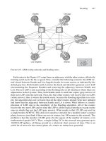
7.2 Pseudonodes
See Figure 7.4 for an illustration of six routers that are located on the same LAN. The LAN
is transitive; this means that all the routers can see each other. Each of the routers gener-
ates an LSP and tells the world that it has five neighbours on the LAN by explicitly list-
ing them inside the IS Reachability TLV #2 or #22.
Any-to-any connectivity lets grow the size of the link-state database by an order of
O(N
2
). This is often referred to as the N
2
problem.
7.2.1 The N
2
Problem
Figure 7.5 illustrates the relationship between the size of IS-reach information in the
link-state database and the number of routers on a LAN. Arguably the absolute size of the
link-state database is a moderate problem compared to the dynamic effects of a full-mesh
advertisement. Every time a new router N gets on the LAN, all the other routers (N Ϫ 1)
that have been on the LAN previously need to update their LSPs to list the adjacency to
the new router. This results in a massive LSP update storm because all the routers on the
LAN need to tell the network that there has been a change in adjacencies. The same
update storm happens if a router is disconnected from the LAN.
The dynamic component (routers joining or leaving the sub-net) is a more important
problem than database storage size.
186 7. Pseudonodes and Designated Routers
10s
Hello Timer
t (s)
2 100 4 6 8
Random
jitter
1 3 5 7 9
2.5s
F
IGURE 7.3. A 25 per cent jitter on the basis of a 10 s timer results in a random Hello between
7.5 and 10 s