The Complete IS-IS Routing Protocol- P23 pptx
Bạn đang xem bản rút gọn của tài liệu. Xem và tải ngay bản đầy đủ của tài liệu tại đây (522.41 KB, 10 trang )
In the example the original 36.5 KB stream is first split into 25 application segments
that are 1460 bytes in size. Next the TCP header that holds the applications port numbers
and other information is prepended which adds 20 bytes resulting in a frame that is called
a TCP segment, which is 1480 bytes in size. The TCP segment gets prepended by an IP
header, which gets prepended again by the Ethernet 802.3 headers. Ultimately the Ethernet
preamble and the CRC32 checksum gets added to the frame resulting in 1526 byte physi-
cal frame that is ready for transmission.
How does the TCP stack know that it has to split the original email stream into chops
of 1460 bytes?
Each layer in the OSI Reference Model has a constant called the maximum transmis-
sion unit (MTU). There is an MTU for TCP, there is one for IP and there is of course one
for Ethernet, as well as for any other physical circuit. What most networking stacks do is
backtracking of the MTU from the underlying circuit. Going back to the example, the first
MTU that is determined is the one of the Ethernet circuit. The MTU here is defined as per
the Ethernet specifications and is set to 1518 bytes. Meanwhile most Ethernet chipsets
have support for frames larger than 1518 bytes up to 9 KB. 1518 bytes represents the low-
est common denominator that each Ethernet device has to understand. The higher layer
MTUs are derived from the Layer-2 MTU. They do vary dependend on the encoding size
of the Layer-2 protocol. The IP MTU is the Ethernet MTU minus 18 bytes. The 18 bytes
are necessary to store 6 bytes of source and destination MAC address, and 2 bytes for the
Ethernet type field plus 4 bytes for the CRC32 checksum that gets appended to the end of
the frame. The TCP MTU is the Ethernet MTU minus 18 minus 20. The typical IP header
(without IP options that would make it longer) is 20 bytes in size. The story goes on by
deducting 20 bytes of the TCP header size to figure out what the application segment size
is. 1518 – 18 – 20 – 20 ϭ 1460. For each interface, host operating systems calculate the
MTU values to find out what is the maximum frame size that can be sent over a specific
circuit. The operating system tries to avoid breaking an already packaged frame into
pieces by looking at the MTU of the delivering circuit.
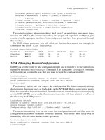
You can display the MTU size of a router by issuing the show interface
<interface-name> command at the command line interface (CLI). This command
is both available in IOS and JUNOS; however, on IOS it does not show you IS-IS-related
information. For IOS a more detailed output can be obtained issuing the show clns
interface <interface-name> command.
JUNOS command output
hannes@Amsterdam> show interfaces so-7/0/0
Physical interface: so-7/0/0, Enabled, Physical link is Up
Interface index: 20, SNMP ifIndex: 19
Description: STM-64 uplink -> Amsterdam-NewYork
Link-level type: PPP, MTU: 4474, Clocking: Internal, SDH mode, FCS: 32,
Payload scrambler: Enabled
Device flags : Present Running
Interface flags : Point-To-Point SNMP-Traps
Link flags : Keepalives
Keepalive settings: Interval 10 seconds, Up-count 1, Down-count 3
Fragmentation and the OSI Reference Model 225
Keepalive: Input: 96933 (00:00:04 ago), Output: 97571 (00:00:04 ago)
LCP state: Opened
NCP state: inet: Opened, inet6: Not-configured, iso: Opened, mpls: Not-
configured
Input rate : 268007728 bps (84371 pps)
Output rate : 376305576 bps (86296 pps)
SONET alarms : None
SONET defects: None
Logical interface so-7/0/0.0 (Index 14) (SNMP ifIndex 28)
Flags: Point-To-Point SNMP-Traps Encapsulation: PPP
Protocol inet, MTU: 4470, Flags: None
Addresses, Flags: Is-Preferred Is-Primary
Destination: 192.168.5.144/30, Local: 192.168.5.146
Protocol iso, MTU: 4470, Flags: None
You can see in the JUNOS output that there is a clear separation between the physical
interface and the logical interfaces and what kinds of protocols are spoken on the inter-
faces. The physical interface so-3/0/0.0 has got a Link-MTU of 4474 bytes. The logical
interface so-7/0/0.0 (not the trailing additional trailing zero) has two protocols configured
– ISO for running the complex of ISO protocols (but limited to IS-IS and ISHs in JUNOS)
and IPv4. The Protocol MTU is 4 bytes less (4470) the Link MTU due to the PPP overhead.
In IOS you can display the IS-IS MTU for a given interface using the show clns
interface command. Because the default encapsulation 802.3 LLC, which is in Cisco’s
terminology also called the SAP, is used, the MTU is being set to 1497 bytes.
IOS command output
London>show clns interface
Ethernet0 is up, line protocol is up
Checksums enabled, MTU 1497, Encapsulation SAP
ERPDUs enabled, min. interval 10 msec.
CLNS fast switching enabled
CLNS SSE switching disabled
DEC compatibility mode OFF for this interface
Next ESH/ISH in 32 seconds
Routing Protocol: IS-IS
Circuit Type: level-2
Interface number 0x2, local circuit ID 0x3
Level-2 Metric: 10, Priority: 64, Circuit ID: London.03
Number of active level-2 adjacencies: 3
Next IS-IS LAN Level-2 Hello in 79 milliseconds
[… ]
As you have seen, JUNOS calculates the MTU on a per protocol basis as well. Generally
speaking, it is important to understand that the MTU is a property of both physical inter-
faces and protocols related interfaces – there is no single MTU value per router interface.
Whenever you hear somebody talking just about an MTU then you have to ask straight
226 9. Fragmentation
“what MTU are you talking about?” Ethernet, PPP, IP, MPLS, IPv6 MTU? An individual
circuit can hold up to five different MTU values – true multiprotocol enterprise routers
like the Cisco 7500 series calculate probably even more than five MTUs per circuit.
There is one MTU for each protocol for each physical interface.
9.2 The Too-small MTU Problem for IP
The sender of the email message in the example tries to package the frame in order to fit per-
fectly to the maximum frame sizes of the underlying physical interface. What will happen if
the sender is located on a physical circuit with a big physical MTU and one of the transit
routers does not support that big-sized MTU? Consider Figure 9.2. The sender is located at
a network segment that can transmit to a maximum packet size of 9172 packets. Typical
examples for such a circuit would be Gigabit Ethernet “Jumbograms” or an ATM circuit.
According to Figure 9.1 the operating system calculates the Maximum Segment Size (MSS)
that TCP can accept in order to avoid sending oversized frames. The MSS is calculated by
deducting the ATM overhead (SNAP frame size) and the IP plus TCP overhead resulting in
a 9127 byte original application segment. Finally the sender dispatches the frame and it
arrives at Router A. Next Router A determines the outgoing interface by doing an IP lookup.
Before Router A starts to transmit the frame it first checks if the outgoing interface
supports the frame size of the frame to be forwarded. The Interlink between Router AS and
Router B is a SONET/SDH link, which has an MTU of 4474 bytes. From the IP perspective,
the frame is 9167 bytes, does not fit on the outgoing circuit and cannot be transmitted.
There are three general ways of solving the varying-MTU problem:
1. Assume a minimum MTU that every circuit has to support
2. Design the carrying protocol to support fragmentation
3. Run an MTU discovery protocol
The TCP/IP family of protocols makes use of all three techniques. First of all it guar-
antees that each IP circuit can have at least an IP MTU of 576 bytes. If an application does
not want to probe the path for maximum MTU or avoid any complex fragmentation and
reassembly schemes then it simply does not send IP frames longer than 576 bytes over the
wire. All the networking media that IP runs on has to have a mandatory support of 576
bytes otherwise the physical media would not be standardized by IP standardization com-
mittees like the IETF. That is the simplest but also most effective way of fragmentation
avoidance. The drawback here is that there may be a lot of overhead: 45 bytes of transport
overhead (TCP, IP and ATM SNAP header) compared to a total frame size of 9172 bytes
means an overhead of 0.5 per cent. However, 45 bytes of transport overhead compared
to a “coward” MTU of 576 means an overhead of 7.8 per cent. Quite a difference if you
The Too-small MTU Problem for IP 227
MTU 9172
MTU 1518
MTU 4474
Sender Receiver
Router A
Router B
F
IGURE 9.2. How does the sender know the MTUs of all the intermediate network segments?
consider for instance file-sharing applications (such as Gnutella, Kazaa and Morpheus),
which are so common these days on the Internet.
The second way of dealing with too-small MTUs is that the underlying network pro-
tocol supports fragmentation methods that can be executed by intermediate routers.
Fragmentation means that even an Intermediate System in the transmission path like a
router may further chop the IP packet to transmit it over smaller MTU circuits. During
the fragmentation process the router figures out how many fragments it needs and then it
has to figure out the position of the fragment relative to the original packet. The IP pro-
tocol was designed from day one to have the capability of fragmentation. In the IP pro-
tocol there are several fields dedicated to fragmentation. See Figure 9.3 for an overview
of the IP header and which fields are dedicated to fragmentation.
The first field is the Fragment ID. Each frame that is fragmented gets a unique 16-bit
ID so that the receiver can correctly reassemble it. That is necessary, for instance, if you
have two flows between a pair of hosts and both flows get fragmented. This ID identifies
the two flows and helps the receiver to separate the fragments of the two flows. In hard-
ware-based routers this is typically a simple counter that is simply incremented. Is this a
perfect scheme? No – there may still be collisions – imagine a massive amount of flows
that need to get fragmented and by accident the first flow and the 65,536th flow (this is
when the 16-bit ID space overlaps) belongs to the same host. However, operational expe-
rience has proven that even such a simple scheme proved to be good enough. The right-
most 13 bits is called the Fragment-offset field. The Fragment-offset field is encoded in
units of 8 bytes. Using 3 bits, 2^13 ϭ 8192 unique offsets can be represented. Each offset
is multiplied by 8 bytes which results in 65,536 bytes – the maximum size of an IP packet.
The Flags field consists of 3 bits. The MSB must be set to 0. The DF (Don’t Fragment) bit
is used to indicate if the sender of the packet does not want to have it fragmented. If one
of the circuits has too small an MTU and the DF bit is set then the router will respond
228 9. Fragmentation
Source IP Address
Destination IP Address
TTL
Identification
Total Length
Protocol Header Checksum
Fragment Offset
Flags
TOS
Version
Header
Length
R
0
DF MF
FIGURE 9.3. The gray-shaded fields are used for fragmentation-related purposes
using an Internet Control Message Protocol (ICMP) to indicate that there has been a prob-
lem. The More Fragment (MF) bit is an indicator for the receiver to wait with reassem-
bling the frame. Typically all fragments except the last fragment do have this bit being set.
For a better understanding of the fragmentation related fields in the IP header, go back
to the example shown in Figure 9.2.
If the 9167 bytes size frame needs to get fragmented the router first has to figure out
how many fragments it will need. The PPP overhead of the link between Router A and
Router B is 4 bytes, therefore the IP MTU on a SONET/SDH PPP Link is 4474 – 4 ϭ 4470
bytes. Chopping up 9167 bytes requires three fragments as 9167/2 is 4584 and this would
not fit. The router tries to figure out what the next 8-octet boundary is to chop the frame.
Recall in the IP header fragmentation in 8 byte chunks is allowed due to the encoding
scheme and encoding space of only 13 bits. The fragment offset is expressed in 8-byte
units. The first fragment will be 4464 bytes as the next 8-octet boundary below 4470 is
4464. Fragment #2 will also be sized at 4464 bytes. The last frame has the MF bit cleared
(as opposed to the first two fragments) and is sized to 239 bytes. The Fragment ID will be
identical in all three fragments. The Fragment offset will be 0 in the first fragment, 558
(558 * 8 ϭ 4464) in the second fragment and 1116 (2 * 558 * 8) in the last fragment. That
is enough information for the receiver to reassemble the original packet. In the IP world
the reassembly is not done by routers, the hosts implement it – therefore each operating
system’s IP stack must support reassembly of fragments.
Even if these mechanisms sound convenient at first sight, the idea that fragmentation
is generally a thing to avoid only came after years of operating large networks. The TCP
stack does not think in terms of fragments, it only thinks in terms of TCP segments –
so if a fragment that has been generated by the IP Layer is lost, the entire frame is
re-transmitted (and fragmented again by intermediate routers). In congested networks
the “goodput” of fragmentation approaches zero depending on the overload level.
The third way is the most sophisticated. Before transmitting the message stream the
path to the receiver is probed for the maximum MTU. This is possible by using fields in
the IP header in a special way. The first packet that the application sends is sent using the
full MTU size. However, the sender also sets the DF bit in the IP header. This does mean
that, referencing our first example, Router A would send an ICMP back to the sender
telling it that a fragmentation attempt was refused due to a set DF bit in the header. There
is a dedicated ICMP message for this purpose which is defined in RFC 792.
Now the application tries to send the first segment using a lower MTU. If it gets an
ICMP message back it tries again with a lower MTU unless it does not get back an ICMP
error message. The exact algorithms for how the transport protocols estimate the MTU
for the next try are out of the scope of this book. If you are interested in these probing
techniques, RFC 1191 is a good place to start to learn about path MTU discovery. All
modern transport stacks make use of path MTU discovery.
You have seen in this section how the IP protocol deals with frames that are in certain
segments in a network too big to deliver. IP proved to be a quite flexible protocol as there
are three different ways of dealing with the too-small-MTU problem that are: avoid, frag-
ment or probe. In the next section you will learn about the messages in the IS-IS protocol
that can get larger than the MTU and how IS-IS deals with it. For better illustration we will
reference back to the three ways of how the IP protocol fixed the too-small-MTU problem.
The Too-small MTU Problem for IP 229
9.3 The Too-small MTU Problem for IS-IS
IS-IS may generate frames that are larger than a single-link MTU. Just think of a large
router that is injecting hundreds of IP prefixes. The space in (for example) an Ethernet
packet may not be sufficient to store that vast amount of data. How is IS-IS dealing with
link MTUs that are too small to convey a large amount of reachability information?
Reconsider the three ways that the IP family of protocols solved the small-MTU problem:
•
Probing the path and finding out what the largest MTU is – this is by concept impos-
sible as IS-IS uses flooding for distributing its information. Flooding has no session
orientation. Session orientation is needed for probing a path. Flooding basically
means all paths. So path MTU discovery is not the tool of choice for finding out what
the smallest MTU in the network is.
•
Fragmenting at the Network Layer – unlike the IP routing protocols (OSPF, BGP) IS-
IS runs directly on Layer-2 according to the OSI Reference Model. In the basic
Ethernet protocol there is no support for fragmenting Ethernet frames. There is no
support built into the Ethernet protocol that allows fragmenting packets like IP did,
using fields like Fragment ID, Fragment Offset and the DF, MF bits. So fragmentation
at the Ethernet level is not a choice either. What IS-IS implements is support to extend
large messages over several packets. Arguably such a thing could best be described as
Fragmentation built into the application IS-IS. The packet types and fields that IS-IS
uses for multi-packet messages will be described shortly.
•
Assuming a minimum MTU – IS-IS assumes a minimum MTU of 1492 bytes
that every segment in the network must support. If there is a link MTU smaller than
1492 bytes then IS-IS simply refuses to build adjacencies. IS-IS checks the MTU during
the handshake phase once new adjacencies are brought up. Why 1492 bytes? The rec-
ommendation to use 1492 bytes was due to the Ethernet MTU of 1518 bytes. How are
1518 bytes and 1492 related? Reconsider the structure of the IS-IS standard encapsu-
lation in 802.3 LLC format in Figure 9.4. Subtract the following fields from the 1518
bytes maximum Ethernet Frame size:
– 4 bytes FCS
– 6 bytes source MAC address
– 6 bytes destination MAC address
– 2 bytes 802.3 Length field
– 3 bytes DSAP, SSAP and Control byte
The result is 1518 – 21 ϭ 1497 bytes. So why then restrict all IS-IS frames to 1492 bytes?
Recall that the IS-IS designers had to accommodate the possibility that someone may encap-
sulate the IS-IS messages using SNAP encapsulation, which is also shown in Figure 9.4.
At the beginning of the 1980s the Ethernet designers were scared about the small
code-point space that LLC encapsulation had to offer. The Sub-network Access Protocol
(SNAP) was thought of as an extension for LLC Ethernet encapsulation to accommodate a
bigger code-point space. The first application of the bigger code-point space was support for
vendor-specific protocols. Using SNAP there is room for a 3-byte Organizational Unit
Identifier (OID) followed by a 2-byte Protocol ID. Think of a SNAP header as a 5-byte exten-
sion to the 3-byte LLC header. Such extension schemes are often used in the communications
230 9. Fragmentation
Destination MAC Address
0180:c200:0014
or 0180:c200:0015
Bytes
6
6
2
1
1
1
min.: 27
max.: Link MTU-21
Source MAC Address
IEEE 802.3 Length field
IEEE 802.3 DSAP
IEEE 802.3 SSAP
IEEE 802.3 Control
IS-IS common header & TLVs
FCS
0xFE
0xFE
0x03
4
Destination MAC Address
0180:c200:0014
or 0180:c200:0015
Bytes
6
6
2
1
1
1
min.: 27
max.: Link MTU-21
Source MAC Address
IEEE 802.3 Length field
IEEE 802.3 DSAP
IEEE 802.3 SSAP
IEEE 802.3 Control
IS-IS common header & TLVs
FCS
0xAA
0xAA
0x03
4
SNAP header OUI
3
0
SNAP header PID
0x80FE
2
802.3
SNAP Encapsulation
802.3
LLC Encapsulation
F
IGURE
9.4. IS-IS formally specified encapsulation over 802.3 LLC and 802.3 SN
AP Layer-2 encapsulation; however, all implementations today use
802.3 LLC encapsulation
231
industry. Most protocols have a special code-point reserved for further extension. In the LLC
protocol, it is 0xAA that indicates that there is a 5-byte SNAP header to parse.
This is where the 5-byte difference between 1497 and 1492 comes from. The ironic
thing here is that although absolutely no vendor ever implemented IS-IS over SNAP
encapsulation, all implementations honour the 1492 bytes size of this “would-be-SNAP-
encapsulated” boundary. Virtually all IS-IS implementations support just the LLC encap-
sulation, which leaves room for 1497 bytes for an IS-IS frame over standard Ethernet
technology.
Figure 9.5 shows the output of a real-word IS-IS frame decoded by Ethereal, a public-
domain protocol analyzer ().
Frequently students in classes notice that a router sends out the first set of Hellos up to
the maximum size of an Ethernet frame to detect the MTU of the link, that the length of
the IS-IS frame is 1497 bytes. You can check that out using the following debug and
monitoring commands.
Tcpdump/JUNOS command output
hannes@London> monitor traffic Interface fe-0/0/0
00:01:36.850702 OSI, IS-IS, length: 1497
L1 Lan IIH, hlen: 27, v: 1, pdu-v: 1, sys-id-len: 6 (0), max-area: 3 (0)
source-id: 0000.0000.0002, holding time: 13s, Flags: [Level 1, Level 2]
lan-id: 0000.0000.0002.02, Priority: 64, PDU length: 1497
IS Neighbor(s) TLV #6, length: 6
IS Neighbor: 0002.b32b.0e52
Protocols supported TLV #129, length: 1
NLPID(s): IPv4
IPv4 Interface address(es) TLV #132, length: 4
IPv4 interface address: 193.83.223.236
Area address(es) TLV #1, length: 4
Area address (3): 49.0001
Padding TLV #8, length: 255
Padding TLV #8, length: 255
Padding TLV #8, length: 255
Padding TLV #8, length: 255
Padding TLV #8, length: 255
Padding TLV #8, length: 160
On a router running IOS you can find out how big the packets that the router sends out
are by using the debug isis adj-packets command.
IOS command output
London#debug isis adj-packets
IS-IS Adjacency related packets debugging is on
Jun 9 20:25:14.319 UTC: ISIS-Adj: Sending L2 LAN IIH on Ethernet0, length 1497
Jun 9 20:25:14.575 UTC: ISIS-Adj: Rec L2 IIH from 00d0.ba58.7e4b (Ethernet0),
cir
type L2, cir id 0010.0100.1005.03, length 1497
232 9. Fragmentation
F
IGURE
9.5. An IS-IS Frame recorded by Ethereal, a public domain Protocol
Analyzer
233
It has already been mentioned that the official MTU that each circuit must support is
1492, as defined in the IS-IS base specification ISO 10589. However, as all vendors only
implement LLC encapsulation, the unofficial MTU (don’t quote us on that) that each
IS-IS may use is 1497 bytes.
The next section takes a closer look to the term application level fragmentation and
what it means. All the different IS-IS packets and how they are prepared for multi-packet
messaging will be discussed.
9.4 IS-IS Application Level Fragmentation
IS-IS uses three different packet types for various purposes:
1. Hellos (IIHs) for neighbour discovery and MTU check
2. Sequence number packets (SNPs) for synchronization and reliable updates
3. Link-state packets (LSPs) for conveying reachability information
9.4.1 Hellos (IIHs)
The Intermediate System to Intermediate System Hello PDU, or IIH, is used for neigh-
bour and MTU discovery. The purpose of neighbour discovery was explained in Chapter
5, “Neighbour Discovery and Handshaking”. There is also an MTU check that verifies if
both ends of an IS-IS adjacency comply with the minimum MTU of 1492 bytes. IS-IS
achieves that check by using a technique called padding. Using padding, the Hello mes-
sage is artificially pumped up to the MTU size of the link, or 1492 bytes. Whether the
update gets pumped up to just 1492 bytes or the full MTU size is a decision that is solely
dependent on the implementation of the IS-IS protocol. For instance, JUNOS only pads
up to 1492 bytes but IOS always tries to pad to the maximum MTU size. A typical IIH
(Hello message) is between 40–70 bytes these days. The size of the Hello message may
vary as all new capabilities are added to the base IS-IS protocol are indicated in the Hello
message, and it therefore gets bigger through the years as capabilities are added to IS-IS.
There has been a trend in the past that the IS-IS Hello message gets bigger on average by
5 bytes each year. Ultimately, this is not an issue as there is quite a lot of headroom to
grow until the max IIH packet size of (worst-case) 1497 bytes is reached. Some imple-
mentations like IOS can even utilize the full-link MTU for Hellos, which is nice because
it postpones worries like these even more. Changing the Hello size is a purely link-local
decision and as long as both parties do not complain about the large Hellos, everything
will be fine and the adjacency goes into Up state.
However, even when an IS-IS Hello is 70 bytes in size, it is still far off the minimum
MTU size of 1492 bytes that every IS-IS circuit has to support. How does IS-IS pad from
70 bytes of content to 1492 bytes? There is a special Padding TLV that helps to add
nonsense data in a structured way just to make the frame bigger. In Figure 9.6 you can
see the structure of the Padding TLV.
There is more about TLV encoding in Chapter 11 “TLVs and Sub-TLVs”. The Padding
TLV may contain an arbitrary set of data. The Padding TLV can also occur several times
234 9. Fragmentation