The Complete IS-IS Routing Protocol- P25 pptx
Bạn đang xem bản rút gọn của tài liệu. Xem và tải ngay bản đầy đủ của tài liệu tại đây (149.99 KB, 10 trang )
9.5 Summary
Contrary to IP routing protocols, IS-IS cannot rely on a network layer to do fragmentation
for it. IS-IS runs directly on the link-layer, which has no possibility of fragmenting frames.
IS-IS therefore needs to apply a few techniques to get around the too-small MTU problem
if it has to transmit a message that is larger than the MTU. The two techniques IS-IS uses
fall under the category of fragmentation avoidance and application level fragmentation.
IS-IS assumes a minimum MTU that every link has to support. This limit today is theoreti-
cally 1492 and in practice 1497 bytes. Additionally in several packet types in IS-IS there
is support for multi-packet messages like CSNPs and LSPs. There are also details of how
the application IS-IS should fragment in order to avoid network-wide churn. “Cluey”
implementations think in terms of fragments and try only to rebuild fragments that have
been affected by an adjacency change. In current network architectures, the distributed
LSP storage space is typically only utilized at 10 per cent, and even if the space could
become exhausted, the IS-IS working group has come up with a solution that is similar to
modelling adjacencies on a large LAN. There is also the possibility of raising the 1492
byte limit of LSP buffer size as all modern interface cards, especially in core environ-
ments, support MTUs up to 4474 bytes. Although not needed today, these developments
are a good proof that the IS-IS infrastructure will exist for a long time to come in networks.
IS-IS Application Level Fragmentation 245
8
Synchronizing Databases
Link-state protocols rely fundamentally on the fact that each router in a given area has
the same view of the topology. Sharing the same view is the foundation for computing
converged routes. Convergence means that each router computes routes in a way that moves
packets one hop closer to the destination. If routes are not convergent, packets can take
extra hops in the network to reach the final destination. The worst case for misaligned
routes is a forwarding loop where packets are bounced back and forth between a pair of
routers. In a changing network it is therefore paramount to get to a synchronized view
of the topology as quickly as possible. New routers connected to the network need to
query their neighbour’s link-state databases to get on the same page as quickly as pos-
sible. This chapter discusses the IS-IS mechanisms to initially synchronize link-state
databases between routers and periodically update the databases.
This chapter starts with a detailed discussion of the consequences of link-state data-
base misalignments. It continues with a detailed explanation of database synchronization
on point-to-point and broadcast links. Finally, refinements to ISO 10589 for increasing
the robustness of the link-state database synchronization process are presented.
8.1 Why Synchronize Link-state Databases?
Unlike distance vector or path vector protocols, such as RIP or BGP, which compute their
routes by travelling through the network, link-state protocols make a local computation
based on shared and identical topological information. To contrast this difference better,
let’s consider the following example: Figure 8.1 shows how RIP calculates the distance to a
network. Router A is locally connected to the sub-net 192.168.1/24. The router is distribut-
ing its reachability information to the prefix 192.168.1/24 by sending a RIP update to all of
its neighbours (Router B and Router C) with a metric of 1. Routers B and C distribute the
information further to other neighbouring routers by incrementing the metric field by one.
Routers D and E, which receive the update, install the prefix 192.168.1/24 with a metric of
2 in their routing and forwarding tables. Observe that the actual calculation of the metric
happens in a distributed fashion: Routers D and E do not know where the prefix origin-
ated. All they know is that it is two routers away and that Routers B and C have received
the prefix. So Routers D and E do not have any topological visibility with regard to the pre-
fix. Each router modifies the original advertisement by incrementing the metric field.
Link-state protocols, like IS-IS, work differently. Each IS-IS router in a given routing
domain has to generate its own view of the local network to its neighbours. Next, all these
205
individual, local views are passed on to the other routers. No router is allowed to change the
original information. Ultimately, each router has the view of all other routers’ neighbours.
Based on all topological information that is available, the router can now independently
construct a network topology graph and extract IP reachability information.
If the link-state databases are not synchronized, routers do not calculate routes that bring
packets to their ultimate destination. Figure 8.2 shows the effect of desynchronized link-
state databases.
The link between Washington and Frankfurt is broken. The Washington router knows
immediately that the link is broken because it is directly connected and therefore senses
a link loss in the following three ways:
•
Missing IIHs
•
Missing Layer-2 keep-alive packets
•
Loss of carrier or loss of framing (on SONET/SDH circuits only)
In the first case, routers exchange IIHs to verify at the Network Layer that the exchange
of control traffic works. The neighbour router is declared down after the hold time period.
The hold time period is not a fixed value and may vary. An adjacent router will indicate
the hold time period inside IIH packets.
The second indicator concerns the fact that routers periodically exchange Layer 2
(Data Link Layer) keep-alive messages to verify the integrity of the link. Virtually all
206 8. Synchronizing Databases
Router B Router C
Router D Router E
Router A
192.168.1/24
via Router A
Metric 1
192.168.1/24
via Router C
Metric 2
192.168.1/24
via Router A
Metric 1
192.168.1/24
via Router B
Metric 2
192.168.1/24
via ETH 0/0
Metric 0
192.168.1/24
FIGURE 8.1. RIP sends out information about local networks plus remote networks by incrementing
the metric field
(but Ethernet) OSI RM Layer 2 Protocols have embedded live-ness protocols that exchange
keep-alive messages). If there is no response from the remote end for a certain amount of
time (typically less than 30 seconds), then the link is declared down because of the inabil-
ity to maintain a valid two-way connection. Loss of Layer 2 keep-alives triggers a so-called
interface-down event that is propagated to the routing protocol stack.
Finally, modern routers often have optical interfaces. Here the carrier is the light. If you
pull the optical fibre out of a router, then a loss-of-light (LOL) error is generated, which
Why Synchronize Link-state Databases? 207
Pennsauken
Frankfurt
London
New York
Paris
22000
31500026000
250000
87000600000
22000
Routing Loop
between New York
and Washington!
Washington
315000
FIGURE 8.2. The link-state database of New York is not in sync, which causes a forwarding loop
triggers an interface-down event. Serial interfaces, such as T1/E1, E3/T3, and Packet-over-
SONET (POS) links, have strict framing requirements where even idle link data (no live
packets) have to be framed in a certain format. The advantage is that a receiver can detect
problems with the transmission framing even during idle periods without packet traffic. This
is in contrast (for example) to Ethernet framing where idle periods (that is, where there is no
transmission of packets) do not generate any signal. In addition, a loss-of-framing (LOF)
error generates an interface-down event, which is propagated to the routing protocol stack.
Next, Washington schedules an SPF run based on the new topology information. The
Washington router re-calculates the new best paths to reach all IP sub-nets in the network.
Both Washington and Frankfurt (working on the same task in parallel) on the other side will
disseminate their new view towards their neighbours. In the meantime, strange things begin
to happen. Consider the traffic that flows from Washington to Amsterdam. Before the link
break, the traffic was routed over the intact link by way of Frankfurt. After the SPF recalcu-
lation, the best path to Amsterdam is through New York and London. The problem is that the
network has not yet converged. So New York does not know about the changed topology.
Based on New York’s latest SPF calculation (which still assumes that the link between
Washington and Frankfurt is working), the best path to Amsterdam is through Washington.
So traffic to Amsterdam is sent to New York, then it is sent back to Washington, then the traf-
fic is sent again to New York and so on – a temporary or transient forwarding loop has
formed and the forwarding loop will persist until the updated topology view has arrived at
New York and New York can then recalculate its routing table. Based on the new routing
table, packets will be forwarded to London instead of being bounced back to Washington.
Synchronized link-state databases and the resulting routing tables are crucial for
bringing packets closer to their final destination. IS-IS has two PDU types for synchron-
izing databases: the CSNP (Complete Sequence Number Packet) and the PSNP (Partial
Sequence Number Packet). The following section illustrates how these packet types are
used for synchronizing link-state databases over LAN and point-to-point circuits.
Unfortunately the mechanisms and the use of CSNPs and PSNPs are different depending
on the media-type, which can be broadcast LAN or point-to-point.
8.2 Synchronizing Databases on Broadcast LAN Circuits
When IS-IS is activated on a router’s interface, the router first sends some IIHs to its neigh-
bours to find out whether the circuit is capable of transporting packets in both directions. In
each of its IIHs the router embeds what it believes to be the Designated Intermediate System
(DIS). In Figure 8.3 you can see the structure of a LAN IIH and the DIS field at the end.
The DIS has a special role on an IS-IS broadcast circuit. Besides the modelling of the
LAN as a topology graph (as you saw in Chapter 7 “Pseudonodes and Designated Routers”,
the DIS has another function relevant to proper synchronization of link-state databases
on LANs. Periodically (typically every 10 seconds), the DIS has to send a directory of its
link-state database, which is received by all the routers on a LAN. Figure 8.4 shows the
structure of a CSNP PDU.
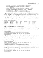
The CSNP Interval is not a hard coded value and can be changed accordingly. Both
IOS and JUNOS permit to set the csnp-interval to an arbitrary value between
208 8. Synchronizing Databases
1–65535 seconds. Low values indicate a high load of generating and receiving CSNPs.
The general recommendation on both platforms is to stick with the default values or
increase the csnp-interval if there are lots of broadcast circuits on the router which
need to be supplied with fresh CSNPs. Note that in IOS you can set the csnp-interval
per level while JUNOS does not permit you to do that.
IOS configuration
interface GigabitEthernet0/2
isis csnp-interval 30 level-1
isis csnp-interval 40 level-2
!
JUNOS configuration
protocols {
isis {
Synchronizing Databases on Broadcast LAN Circuits 209
Intra-domain Touting Protocol Discriminator
Header Length Indicator
Version/Protocol ID Extension
0x83
Bytes
1
1
1
1
1
1
1
1
1
ID Length
PDU Type
R
0
R
0
R
0
PDU Version
Reserved
Maximum Area Addresses
6 (0)
1
3 (0)
0
Reserved
TLV section
0–1467
15, 16
27
circuit
type
1, 2, 3
Source ID
Holding Time
PDU Length
PriorityR
Designated IS LAN-ID
1
ID Length (6)
2
2
1
ID Length (6) ϩ 1
FIGURE 8.3. Each IS-IS router sends what it believes is the Designated Intermediate System at a
given time
interface ge-2/0/0.0 {
csnp-interval 30;
interface lo0.0;
}
}
You can verify the settings by issuing a show isis interface <ifname>
detail command on JUNOS.
hannes@London> show isis interface ge-0/2/0.0 detail
IS-IS interface database:
ge-0/2/0.0
Index: 1, State: 0x6, Circuit id: 0x2, Circuit type: 3
LSP interval: 100 ms, CSNP interval: 10 s
Level Adjacencies Priority Metric Hello (s) Hold (s) Designated Router
1 2 64 1200 9.000 40 Amsterdam.02 (not us)
2 1 64 22000 3.000 40 London.02 (us)
210 8. Synchronizing Databases
Intra-domain Routing Protocol Discriminator
Header Length Indicator
Version/Protocol ID extension
0x83
Bytes
1
1
1
1
1
1
1
1
1
ID Length
PDU Type
R
0
R
0
PDU Version
Reserved
Maximum Area Addresses
6 (0)
1
3 (0)
0
TLV section
34–1459
24, 25
33
Source ID
Start LSP-ID
PDU Length
End LSP-ID
2
ID Length (6) ϩ 1
ID Length (6) ϩ 2
ID Length (6) ϩ 2
R
0
1, 2, 3
FIGURE 8.4. CSNP PDUs are used for conveying the headlines of the link-state database
You cannot verify the csnp-interval settings on an IOS router because the csnp-
interval is not displayed under the show clns interface <ifname> command.
The CSNP on LAN circuits is sent using the well-known functional address AllL1ISs
(0180:c200:0014) or to the well-known functional address AllL2ISs (0180:c200:0015)
depending on the IS-IS level. The IS-IS common header that provides the receiver with
the following information starts the CSNP PDU:
•
Header length (this is always 33 bytes for the CSNP header)
•
IS-IS protocol version that is used (always 1)
•
Length of the System-ID (0 means the standard 6 bytes)
•
Level (L1 CSNPs use PDU type 24, L2 PSNPs use PDU type 25)
•
CSNP protocol version that is used (always 1)
•
Number of area addresses that this IS supports (0 means support for 3 addresses)
The CSNP header holds the following information:
•
PDU length (this is the length of the entire PDU including the common header, the
CSNP header, and the payload)
•
Source-ID (the System-ID plus a trailing zero byte)
•
The Start LSP-ID plus the End LSP-ID (The LSP-ID describe Elements in the link-
state database of the router)
After the CSNP header the rest of the PDU is filled using TLVs. You can learn more
about TLVs in Chapter 11. In CSNP PDUs only two TLVs are used. The LSP-ID TLV #9
is used for link-state database synchronization and the Authentication TLV #10 are used
for integrity checking.
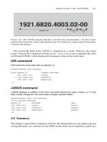
If the entire LSP database fits into a single CSNP PDU, meaning there are no more
than 90 LSP-IDs in the CSNP PDU, then the Start LSP-ID is set to 0000.0000.0000.00-00
and the End-LSP-ID is set to FFFF.FFFF.FFFF.FF-FF (the entire range possible). This is
how the sender tells the receiver that this CSNP contains the full range of LSP-IDs that are
present in the sender’s database. Where does the maximum number of 90 LSP-IDs per
CSNP PDU come from? Recall that 15 LSP-entries fill an LSP-entry TLV with 240 bytes.
Add 2 bytes for TLV overhead to come up with 242 bytes. The LSP-entry TLV can repeat
up to 6 times until the packet is completely full. Now, 6
*
242 ϭ 1452 bytes plus 33 bytes
of header length ϭ 1485 bytes. Therefore, 6 LSP-entry TLVs per packet
*
15 LSP-IDs
per LSP-entry TLV, comes out to 90 LSP-IDs per packet:
Link-state databases that contain more than 90 entries send more than one CSNP PDU.
The first CSNP PDU, Start LSP-ID, is set to 0000.0000.0000.00-00 and the End LSP-ID
of the last CSNP PDU is set to FFFF.FFFF.FFFF.FF-FF. This all ones ending tells the
receiver that this CSNP is the last one to describe the link-state database, and the trans-
mission of LSP-IDs is completed. Between the first PDU and the last, other CSNP-PDUs
insert the LSP-ID of the first and the last LSP-ID reported using the LSP-entry-TLV #9
in the CSNP header in the Start LSP-ID and End LSP-ID fields. It is assumed that the
LSP-IDs are ordered by LSP-ID and they arrive in sequence.
6
LSP-Entry TLVs
packet
* 15
LSP-IDs
LSP-Entry TLV
90
LSP-IDs
packet
ϭ
Synchronizing Databases on Broadcast LAN Circuits 211
CSNP
TLVs
1921.6801.4001.00-00
Sequence 0x289
Lifetime 324
Checksum 0xfc11
1921.6802.7152.00-00
Sequence 0x2b
Lifetime 12058
Checksum 0x62a1
CSNP Header:
Start LSP-ID
0000.0000.0000.00-00
End LSP-ID
1921.6802.7152.00-00
CSNP
TLVs
1921.6817.7139.00-00
Sequence 0x135
Lifetime 49653
Checksum 0xcc16
1921.6817.8222.00-00
Sequence 0x2c4
Lifetime 38894
Checksum 0x780c
CSNP Header:
Start LSP-ID
1921.6817.7139.00-00
End LSP-ID
1921.6817.8222.00-00
CSNP
TLVs
1921.6817.8223.00-00
Sequence 0xcf6
Lifetime 63449
Checksum 0x948f
1921.6817.9058.00-00
Sequence 0x2a09
Lifetime 63449
Checksum 0xb918
CSNP Header:
Start LSP-ID
1921.6817.8223.00-00
End LSP-ID
1921.6817.9058.00-00
CSNP
CSNP Header:
Start LSP-ID
1921.6818.1211.00-00
End LSP-ID
ffff.ffff.ffff.ff-ff
TLVs
1921.6818.1211.00-00
Sequence 0x357
Lifetime 33384
Checksum 0xb694
1921.6818.1255.00-00
Sequence 0x38a
Lifetime 25225
Checksum 0xcaba
t
CSNP #1
(first)
CSNP #2
CSNP #3
CSNP #4
(last)
F
IGURE
8.5. Link-state databases bigger than 90 LSPs need multiple CSNP PDUs for a full report
212
Synchronizing Databases on Broadcast LAN Circuits 213
Figure 8.5 shows an example of a multi-packet CSNP, which is sent as a sequence of
four frames. The first CSNP has the Start LSP-ID set to all zeros. The End LSP-ID is set to
the last LSP-ID that is reported in the first CSNP (1921.6802.7152.00-00). The inter-
mediate CSNPs set their Start and LSP-ID fields according to the first and last LSP-ID
that is reported in the PDU. Finally, the last CSNP of the full update sets the End-LSP ID
to all ones (FFFF.FFFF.FFFF.FF-FF) indicating that the full-report of all LSP-IDs is now
completed.
The payload section of the CSNP PDU is filled with an information element called the
LSP Entry. The LSP Entry is placed in the CSNP PDU by use of TLV encoding. You can
find more information about TLV encoding in Chapter 11 “TLVs and sub-TLVs”. Figure 8.6
shows the structure of the LSP Entry TLV. The TLV header consists of two bytes – the
Type and the Length value. The Type value is #9 and the Length value is always a mul-
tiple of 16. The LSP Entry is a structure of 16 bytes that can be repeated up to 15 times
in a TLV. The LSP Entry holds the header information of an LSP in the link-state data-
base. This information is:
•
LSP-ID (6 byte System-IDs plus 1 byte node-ID plus 1 byte fragment number)
•
Sequence number (4 bytes)
•
Remaining lifetime (2 bytes)
•
Checksum of the corresponding LSP (2 bytes, standard Fletcher checksum)
By using these four parameters, an LSP can uniquely be identified in a link-state database.
Additionally, for each LSP, two informative flags are kept for each circuit in order to con-
trol flooding, re-flooding, and acknowledging LSP updates. These two flags are called
TLV Type
TLV Length
Remaining Lifetime
9
Bytes
1
1
ID Length (6) ϩ 2
2
4
2
LSP-ID
Sequence Number
Checksum
N * 16
Remaining Lifetime
ID Length (6) ϩ 2
2
4
2
LSP-ID
Sequence Number
Checksum
FIGURE 8.6. The LSP Entry TLV is a container for LSP headline figures like Sequence Number,
Lifetime and Checksum