Scalable voip mobility intedration and deployment- P22 pptx
Bạn đang xem bản rút gọn của tài liệu. Xem và tải ngay bản đầy đủ của tài liệu tại đây (221.17 KB, 10 trang )
210 Chapter 6
www.newnespress.com
beacon. That doesn’t guarantee that the client will hear the beacon at exactly that time,
however. Beacons can be delayed if the air is occupied at that time. Furthermore, because
beacons are sent out as broadcasts, the client might just miss the beacon or the beacon can
be collided with. If the client does hear the beacon, it can then go to sleep so long as no
traffic is buffered for it.
Clients may also skip beacons. They would do this to save additional battery, at the expense
of increasing the amount of time the frames would be buffered. Clients usually let the
access points know how many beacons they will skip by sending a listen interval in their
Association Request messages. A listen interval of 1 means that the client will wake for
every beacon; a listen interval of 10 means that the client will wake only for every tenth
beacon. Be careful, however; some clients do not follow the listen interval they state,
waiting either for more or less beacons than they advertise.
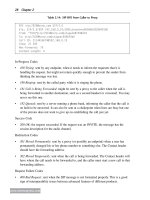
The client signals that it is going to sleep by using the power management bit in any unicast
frame it sends to the access point (except for non-Action management frames). The power
management bit is in the Frame Control field for the frame. When the client sends a frame
Access Point
PSPoll Mechanism
Client Device
Beacon
Null
(PM=1)
Null
(PM=0)
PS
Poll
Data
1 Beacon 0
TIM Bit for Client
In Power Save Mode
Time
ACK
Awake
Awake
Access Point
PSNonPoll Mechanism
Client Device
Beacon
Null
(PM=1)
Null
(PM=1)
Null
(PM=0)
Null
(PM=0)
Data
1 Beacon 0
TIM Bit for Client
In Power Save Mode
Time
ACK
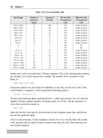
Figure 6.1: Wi-Fi Legacy Power Save
Voice Mobility over Wi-Fi 211
www.newnespress.com
with the power management bit set and when it gets an Acknowledgement in response, it
knows that the access point has heard the client’s change of state and can now go to sleep.
From this moment on, the access point will buffer frames, until the client sends any frame
to the access point with the power management bit not set. That signals that the client is
now awake, and can be sent packets as usual.
While the client is in power save mode, and it wakes to find that its TIM bit is set to signify
that it has frames available for it, the client has two choices on how to gather those frames.
The first choice is known as the PSPoll mechanism, and uses the Power Save Poll (PS Poll)
frames. After the beacon with the client’s TIM bit set, the client would send a PS Poll
frame to the access point. This frame, which is usually acknowledged right away, triggers
the access point to deliver exactly one of the buffered frames for the client. That buffered
frame is put into the transmit queue, using the appropriate access category for WMM. The
frame that is sent also has its More Data bit in the Frame Control field set if there are
subsequent frames that are buffered. Once the client has the frame, it can chose to send
another PS Poll to get another frame. This one-PS-Poll/one-data-frame exchange continues
until the access point’s buffer is drained or the client wishes to sleep more.
The other option the client has is to use the PSNonPoll mechanism. This mechanism is
quite simple: the client simply sends a data frame, usually a Null data frame, stating that it
is no longer sleeping, by clearing the power management bit. The access point will proceed
to queue all of the buffered frames, each using its own WMM access category. The client
can then wait for a certain amount of time, hoping that it got all of the frames it was going
to get, after which it can send another Null data frame, signifying it is going back to sleep.
Any frames that may have still been in a transmit queue might get buffered again by the
access point, for a later PSNonPoll exercise. The advantage of the PSNonPoll mechanism is
that it is simple and doesn’t require a significant back-and-forth. The disadvantage is that
the client has no way of knowing if there are any remaining frames for it, without going to
sleep and waiting for the next beacon.
The choice between PSPoll and PSNonPoll modes is often left up to the client’s software
implementation, and not exposed to you. However, some clients do give a choice up front,
or have specific behavior where they will use one method or the other, depending on how
aggressive you set its power save settings to (using a slider, say). It should be clear that
neither mode is good for quality-of-service traffic, because the client can be forced to wait
as much as a beacon interval (times its listen interval) before it finds out traffic is available.
If the beacon interval is set to the typical 100 milliseconds, and the listen interval is 10,
then that can be up to a second of delay.
Broadcast and multicast frames are also covered in the legacy scheme. However, no polling
is necessary for those frames to be delivered. Instead, the access point sets aside a certain
number of the beacons for multicast traffic. If any client on the access point is in legacy
212 Chapter 6
www.newnespress.com
power save mode, the access point will buffer all multicast traffic. The special beacons
known as Delivery Traffic Indication Messages (the poorly named DTIM) are just like
regular beacons, except that they come every so many beacons—when the next one is
coming is signaled as a part of the TIM in every beacon—and they signal if multicast traffic
is buffered. If multicast traffic is buffered, the TIM has the zeroth bit, corresponding to AID
0, set. If clients receive a beacon with that bit set, they know that the next frames coming
from the access point will be all of the multicast frames buffered. Each multicast frame,
except for the last one, will have the More Data bit set. Thus, clients can stay awake to
collect all multicast traffic, and then go back to sleep after the last multicast data frame,
with the cleared More Data bit, comes through. (Of course, if that last frame is lost, being
multicast, the clients will have to decide on their own when to return to sleep.) The
consequence of the all-or-nothing multicast buffering is that multicast traffic on Wi-Fi when
anydeviceisinpowersaveisnotgenerallysuitableforreal-timetrafc!Lookfor
architectures that provide solutions for this problem if real-time multicast is a priority for
your network.
Finally, I haven’t gone into details on how the TIM bits are compressed. It is not easy to
read the TIM bits by hand, but a good wireless protocol analyzer will be able to read them
for you, and let you know which AIDs are set in any beacon.
6.0.2.2 WMM Power Save
To provide power saving while the mobile device is in a call, the Wi-Fi Alliance came up
with the second power saving technique, WMM Power Save. This technique, based on the
quality-of-service additions in the 802.11e amendment to the standard, acts as a parallel
scheme to the legacy one, using similar concepts but in a way that avoids having to wait for
beacons and can apply on a per-access-category basis.
If you notice, there is nothing in the standard that prevents clients that are using the legacy
power save scheme from ignoring beacons, for the most part, and sending PS Polls
whenever they want. If the client were sure that there is going to be a packet for it waiting
every so often—say, 20 milliseconds—then it could just send PS Polls every 20
milliseconds, collect its data, and have real-time power save. Of course, this doesn’t happen
for legacy power save, because the client has no guarantee that it won’t get some other
frames rather than what it is looking for. However, this is the concept that WMM Power
Save builds on.
WMM Power Save is optional, and support for it is signaled by the WMM information
elements in the Association messages and the beacons. Unlike with legacy power save,
WMM Power Save (capitalized, as it is a formal name) is aware of the WMM access
categories and can apply to a subset of them. The two subsets are delivery-enabled access
categories and trigger-enabled access categories.
Voice Mobility over Wi-Fi 213
www.newnespress.com
First, let’s start with the polling protocol. The client no longer checks the beacons to
see if there is traffic. Instead, it is responsible for knowing that traffic is waiting for it, and
how often. For phones, this is not a problem, as voice is bidirectional and consistent.
Instead of sending a PS Poll frame, or using the PSNonPoll mechanism, the phone
sends data frames in access categories that it has specified to be trigger-enabled. The
access point looks for those data frames, and uses that as a trigger—just as it does in legacy
with Power Save Poll frames—sending packets in response from the power save buffer.
Those packets, however, can only come from the delivery-enabled access categories.
Which categories are delivery- and trigger-enabled are usually specified in the Association
Request from the client—there, a bitmask specifies which categories are legacy and
which are delivery and trigger enabled together—or in TSPEC messages, which we will
come to later.
Here’s a common example. The phone associates, and tells the access point that it
wantsthevoicecategory(AC_VO)tobedelivery-andtrigger-enabled.Thatmeansthatthe
other three categories work on the legacy scheme. If packets come in for those other
categories while the client is asleep, the TIM bit on the beacon will be set and the client
will use legacy power save mechanisms to get the frames. But when a voice packet is sent
to the access point, the access point silently holds onto the packet. The only way the
client can get the voice packet is to send a voice packet of its own. When it does, that
causes the access point to respond with one or more voice packets in its buffer. Unlike
with legacy power save, the client can ask for more than one packet at a time. Using the
concept of a service period, which is set at Association time by the client and specifies
the number of frames the client wants to get for every trigger (either two, four, six, or all),
the access point will send out the correct number of frames. The last frame, whether
because the buffer is empty or the service period has been exceeded, will have a special end
of service period (EOSP) bit set in the QoS header. Once the client gets that frame, it can
go back to sleep.
As you can see, the legacy and WMM Power Save schemes operate simultaneously and
independently. The only overlap is that the client goes into to power save mode for both
schemes simultaneously. This means that devices that are actively using WMM Power Save
should never use the PSNonPoll method during that time, because the client waking up
from power save mode will cause the access point to send all frames, whether they are from
the legacy or WMM Power Save access categories.
The capability to support WMM Power Save should be considered nearly mandatory for
most voice equipment. Some mobile devices use proprietary mechanisms that may or may
not be supported by every access point, but the trend is towards using WMM Power Save.
Of course, the problem with WMM Power Save is that it works well only for voice, but that
is not a concern for us in this book.
214 Chapter 6
www.newnespress.com
6.1 Technologies that Address Voice Mobility with Wi-Fi
The introduction of WMM into Wi-Fi allowed voice to now have a prioritized way of being
carried over the air. But other basic elements of providing a toll-quality voice system
needed to be put in place. Many of these newer techniques borrow from how things are
done on the cellular networks, and work is only beginning now to try to standardize certain
parts of them. How vendors—access point and phone—implement these features goes a
long way towards determining how well the voice mobility network will work.
6.1.1 Admission Control: The Network Busy Tone
Therstconceptthatisneededisprovidinga“networkbusy”tone.Everynetworking
technology has its capacity limits, and given the discussion in Section 6.0.1.1,
Wi-Fi can have some fairly severe ones. As the number of voice calls exceeds the network
capacity, the air becomes crowded with aggressive, high-priority voice packets. This causes
increased loss and can end up hurting the quality of every active call on the air in that
region.
The solution is to not let in the calls that cause the capacity to be exceeded. The goal is to
provide the caller with that network busy signal. (If you have never heard a network busy
tone before, on standard telephones, they sound like the usual caller busy tone, but they
beep at a much faster rate.)
When used for voice, admission control is often called Call Admission Control (CAC),
pronounced“cack.”TherearetwomethodscurrentlyinuseforWi-Fitoprovidethis.
6.1.1.1 SIP-Based Admission Control
The first method is to rely on the call setup signaling. Because the most common
mechanism today is SIP, we can refer to this as SIP-based admission control. The idea is
fairly simple. The access point, most likely in concert with a controller if the architecture in
use has one, uses a firewall-based flow-detection system to observe the SIP messages as
they are sent from the phones to the SIP servers and back. Specifically, when the call is
initiated, either by the phone sending a SIP Invite, or receiving one from another party, the
wireless network determines whether there is available capacity to take the call. If there is
available capacity, then the wireless network lets the messages flow as usual, and the call is
initiated.
On the other hand, if the wireless network determines that there is no room for the call, it
will intercept the SIP Invite messages, preventing them from reaching the other party, and
interject its own message to the caller (as if from the called party, usually), with one of a
few possible SIP busy statuses. The call never completes, and the caller will get some sort
of failure message, or a busy tone.
Voice Mobility over Wi-Fi 215
www.newnespress.com
Other, more advanced behaviors are also possible, such as performing load balancing, once
the network has determined that the call is not going to complete.
The advantage of using SIP flow detection to do the admission control is that it does not
require any added sophistication on the mobile devices than they would already have with
SIP. Furthermore, by having that awareness from tracking the SIP state, the network can
provide a list of both calls in progress and registered phones not yet in a call. The
disadvantage is that this system will not work for SIP calls that are encrypted end-to-end,
suchasbeingcarriedoveraVPNlink.
6.1.1.2 WMM Admission Control
Building on even more of the specification in the 802.11e quality-of-service amendment is
WMM Admission Control. This specification and interoperability program from the Wi-Fi
Alliance,whichisrequiredtoachieveVoiceEnterprisecertication(seeSection 6.3), uses
an explicit layer-2 reservation scheme. This scheme, in a similar vein as the lightly used
RSVP protocol (RFC 2205), requires the mobile device to reach out and request resources
explicitly from the access point, using a new protocol built on top of 802.11 management
frames.
This protocol is heavily dependant on the concept of a traffic specification (TSPEC). The
TSPEC is created by the mobile phone, and specifies how much of the air resources either
or both directions of the call (or whatever resource is being requested) will be taken. The
access point processes the request as an admission controller (a function often placed
literally on the controller, by coincidence), which is in charge of maintaining an account of
which clients have requested what resources and whether they are available.
The overall protocol is rather simple. The mobile device, usually when it determines that it
has a call incoming our outgoing, will send an Add Traffic Stream (ADDTS) Request
message (a special type of Action management frame) to the access point, containing the
TSPEC that will be able to carry the phone call. The access point will decide whether it can
carry that call, based on whatever scheme it uses (see following discussion), and send an
ADDTS Response message stating whether the stream was admitted.
WMM Admission Control can be set to mandatory or optional for each access category. For
example, WMM Admission Control can be required for voice and video, but not for best
effort and background data. What this would mean is that no client is allowed to transmit
voice or video packets without first requesting and being granted admission for flows in
those access categories, whereas all clients would be allowed to freely transmit best effort
and background data as they see fit. Which access categories require admission control is
signaled as a part of the WMM information element, which goes out in beacons and some
other frames.
216 Chapter 6
www.newnespress.com
For WMM Admission Control, it is worth looking at the details of the concepts. The main
concept is one of a traffic stream itself, and how it is identified and recognized. Traffic
streams are represented by Traffic Identifiers (TID), a number from 0–7 (the standard allows
up to 15, but WMM limits this to only 7) that represents the stream. Each client gets its
own set of eight TIDs to use.
Each traffic stream, represented by its TID, maps onto real traffic by naming which of the
eight priority values in WMM will belong to this traffic stream (see Table 6.1). Thus, if the
phone intends to send and knows it is going to receive priority 7—recall that this is the
highest of the two voice AC priorities—it can establish a traffic stream that maps priority 7
traffic to it, and get both sides of the call. In order for that to work, the client can specify
whether the traffic stream is upstream-only, downstream-only, or bidirectional. It is possible
for the client to request both an upstream-only and downstream-only stream mapping to the
same priority (different TIDs, though!), if it knows that the airtime used by the downstream
side is different than the upstream side—useful for video calls—or it may request both at
once in one TID, with the same airtime usage. All of this freedom leads to some complexity,
but thankfully there is a rule preventing there from being more than one downstream and
one upstream flow (bidirectional counts as one of each) for each access category. Thus, the
AC_VOvoiceaccesscategorywillonlyhaveoneadmittedbidirectionalphonecallinitat
any given time.*
The client requests the traffic stream using the TSPEC.
Table 6.3 shows the contents of the TSPEC that is carried in an ADDTS message.
There’s quite a lot of information in a TSPEC, so let’s break it down slowly, using the
example of a 20 millisecond G.711 (nearly uncompressed) one-way traffic flow:
• TheTS Info field (see Table 6.4) identifies the TID for the stream, the priority of the
data frames that belong to this stream, what direction the stream is going in (00 = up,
01 = down, 10 = reserved, 11 = bidirectional), and whether the AC the stream belongs
to is to be WMM Power Save delivery enabled (1) or not (0). The rest of the fields are
not used in WMM Admission Control, and have specific values that will never change
(Access Policy = 01, the rest are 0).
• TheNomimal MSDU Size field mentions the expected packet size, with the highest-
order bit set to signify that the packet size never changes. G.711 20ms packets are 160
* Of course, there had to be a catch. Some devices can carry two calls simultaneously, if they renegotiate their
one admitted traffic stream to take the capacity of both. Because WMM Admission Control views flows as
being only between clients and access points, the ultimate other endpoint of the call does not matter. However,
this is not something you would expect to see in practice.
Voice Mobility over Wi-Fi 217
www.newnespress.com
bytes of audio, plus 12 bytes of RTP header, 8 bytes of UDP header, 20 bytes of IP
header, and 8 bytes of SNAP header, creating a data payload (excluding WPA/WPA2
overhead) of 208 = 0xD0. Because the packet size for G.711 never changes, this field
would be set to 0x80D0.
• TheMaximum MSDU Size field specifies what the largest a data packet in the
stream can get. For G.711, that’s the same as the nominal size. There is no special bit
for fixed sizes, so the value is 208 = 0x00D0. This can also be left as 0, as it is an
optional field.
• TheInactivity Interval specifies how long the stream can be idle—no traffic matching
it—in microseconds, before the access point can go ahead and delete the flow. 0 means
not to delete the flow automatically, and that’s the common value.
• TheMean Data Rate specifies, in bits per second, what the expected throughput is for
the stream. For G.711, 208 bytes every 20 milliseconds results in a throughput of 83200
bits per second.
Table 6.3: WMM admission control TSPEC
TS
Info
Nominal
MSDU
Size
Maximum
MSDU
Size
Minimum
Service
Interval
Maximum
Service
Interval
Inactivity
Interval
Suspension
Interval
Service
Start
Time
…
3 bytes 2 bytes 2 bytes 4 bytes 4 bytes 4 bytes 4 bytes 4 bytes
…
Minimum
Data
Rate
Mean
Data
Rate
Peak
Data
Rate
Maximum
Burst
Size
Delay
Bound
Minimum
PHY
Rate
Surplus
Bandwidth
Allowance
Medium
Time
4 bytes 4 bytes 4 bytes 4 bytes 4 bytes 4 bytes 2 bytes 2 bytes
Table 6.4: The TS info field
Traffic
Type
TID Direction Access
Policy
Aggregation WMM
Power
Save
Priority TSInfo
Ack
Policy
Schedule Reserved
Bit: 0 1–4 5–6 7–8 9 10 11–13 14–15 16 17–23
218 Chapter 6
www.newnespress.com
• TheMinimum Data Rate and Peak Data Rate specify the minimum and maximum
throughput the traffic stream can expect. These are optional and can be set to 0. For
G.711, these will be the same 83,200 bits per second.
• TheMinimum PHY Rate field specifies what the physical layer data rate assumptions
are for the stream, in bits per second. If the client is assuming that the data rate could
drop as low as 6Mbps for 802.11ag, then it would encode the field at 6Mbps =
6,000,000bps = 0x005B8D80.
• TheSurplus Bandwidth Allowance is a fudge factor that the phone can request, to
account for that packets might be retransmitted. It’s a multiplier, in units of 1/8192nds.
A value of 1.5 times as an allowance would be encoded as 0x3000 =
001.1000000000000, in binary.
• Theothereldsareunusedbytheclient,andcanbesetto0.
In other words, the client simply requests the direction, priority, packet size, data rate, and
surplus allowance.
The access point gets this information, and churns it using whatever algorithms it wants—
this is not specified by the standard, but we’ll look at what sorts of considerations tend
to be used in Section 6.1.1.3. Normally, we’ll assume that the access point knows what
percentage of airtime is available. The access point will then decide how much airtime the
requested flow will take, as a percentage, and see whether it exceeds its maximum
allowance (say, 100% of airtime used). If so, the flow is denied, and a failing ADDTS
Response is sent. If not, the access point updates its measure of how much airtime is being
used, and then allows the flow. The succeeding ADDTS Response has a TSPEC in it that is
a mirror of the one the client requested, except that now the Medium Time field is filled in.
This field specifies exactly how much airtime, in 32-microsecond units per second, the
client can take for the flow.
The definition of how much airtime a client uses is based on what packets are sent to it or
that it sends as a part of a flow. Both traffic sent by the client to the access point and sent
by the access point to the client are counted, as well as the times for any RTSs, CTSs,
ACKs,andinterframespacingsthatarebetweenthoseframes.Anotherwayofthinking
about it is that the time from the first bit of the first preamble to the last bit of the last frame
of the TXOP counts, including gaps in between. In general, you will never need to try to
count this. Just know that WMM Admission Control requires that the clients count their
usage. If they exceed their usage in the access category they are using, they have to send all
subsequent frames with a lower access category—and one that is not admission control
enabled—or drop them.
One advantage of WMM Admission Control is that it works for all traffic types, without
requiring the network to have any smarts. Rather, the client is required to know everything
Voice Mobility over Wi-Fi 219
www.newnespress.com
about the flows it will both send and receive, and how much airtime those flows will take.
The network just plays the role of arbiter, allowing some flows in and rejecting others.
Thus, if the client is sufficiently smart, WMM Admission Control will work whether the
protocol is SIP, H.323, some proprietary protocol, or even video or streaming data. The
disadvantage of that, however, is that the client is required to be smart, and all of its
pieces—from wireless to phone software—have to be well integrated. That pretty much
eliminates most softphones, and brings the focus squarely on purpose-built phones.
Furthermore, the client needs to know what type of traffic the party on the other side of the
call will send to it. Some higher-level signaling protocols can convey this, such as with SDP
within SIP, but doing so may be optional and may not always be followed. For a phone
talking to a media gateway, for example, the phone needs to know exactly how the media
gateway will send its traffic, including knowing the codec and packet rate and sizing, before
it can request airtime. That can lead to situations in which the call needs to be initiated and
agreed to by both parties before the network can be asked for permission to admit the flow,
meaning that the call might have to be terminated by the network midway through ringing,
if airtime is not available. Because WMM Admission Control is so new—by the time of
publication, WMM Admission Control should be launching shortly and large amounts of
devices may not yet be available—it remains to be seen how well all of the pieces will fit
together. It is notoriously difficult for general-purpose devices to be built that run the gamut
of technologies correctly, and so these new programs might be more useful for highly
specific purpose-built phones.
6.1.1.3 How the Capacity Is Determined
Through either admission control scheme, the network needs to keep track of how much
capacity is available. From the previous discussions on the effects of RF variability and
cellular overlap, you can appreciate that this is a difficult problem to completely solve.
As devices get further away from the access points, data rates drop. Changing levels of
interference, from within the network or without, can cause increasing retransmissions and
easily overrun surplus bandwidth allowances.
In the end, networks today adopt one of two stands, and may even show both to the user.
The more complicated stand for the network—but simpler for the user—is for the network
to automatically take the variability of RF into account, and to determine its own capacities.
In systems that do this, there is no notion of a static maximum number of calls. Instead, the
system accepts however many calls as it can handle. If conditions change, and fewer calls
can be handled in the system, the network reserves the right to proactively end a client’s
reservation, often in concert with load balancing.
The other stand, simpler for the network but far more complicated for the user, is for the
administrator to be required to enter the maximum number of calls per access point (or
some other static metric). The idea here is that the administrator or installer is assumed to