Introduction to Modern Liquid Chromatography, Third Edition part 5 pptx
Bạn đang xem bản rút gọn của tài liệu. Xem và tải ngay bản đầy đủ của tài liệu tại đây (150.38 KB, 10 trang )
xxxviii GLOSSARY OF SYMBOLS AND ABBREVIATIONS
A
s
peak asymmetry factor; Figure 2.16a
AU absorbance units (UV detection)
b fundamental gradient steepness parameter; Equation (9.4)
B column hydrogen-bond basicity; Equation (5.3)
C column ion-exchange capacity or electrostatic interaction; Equation
(5.3)
CCD chemical-composition distribution
CD cyclodextrin
CDR chiral derivatizing reagent
CE capillary electrophoresis
CEC capillary electrochromatography
CCC countercurrent chromatography
CLND chemiluminescent nitrogen detector
C
m
solute concentration in mobile phase
CMPA chiral mobile-phase additive
CS chiral selector
C-S column switching
C
s
solute concentration in stationary phase
Da Dalton (molecular weight)
DAD diode-array detector
D
m
solute diffusion coefficient (cm
2
/ sec); Equation (2.19)
DMSO dimethylsulfoxide
EC electrochemical
EDTA 1,2-ethylenediamine-N, N, N
,N
-tetraacetic acid
ELSD evaporative light scattering detector
EPA US Environmental Protection Agency
FDA US Food and Drug Association
F
opt
optimum mobile-phase flow rate (mL/min) (Section 2.4.1)
F
s
column-comparison function; Equation (5.4)
F
s
(−C) value of F
s
for non-ionized samples; Equation (6.3)
G gradient compression factor; Equation (9.15a)
H column hydrophobicity; Equation (5.3)
H-B hydrogen bond
HFBA heptaflurobutyric acid
h reduced plate height; Equation (2.18)
h
p
peak height
HP-TLC high-performance thin-layer chromatography
HVAC heating, ventilation, and air-conditioning system
GLOSSARY OF SYMBOLS AND ABBREVIATIONS xxxix
ICH International Conference on Harmonization
ILE immobilized liquid extraction
IMAC immobilized metal affinity chromatography
IPA isopropanol
IQ installation qualification
ISO International Organization for Standardization
IS internal standard
K equal to (C
s
/C
m
)
K
D
SEC distribution coefficient; Figure 13.39; also, Nernst Distribution
Law coefficient; Equation (16.1)
k
EB
value of k for ethylbenzene (different columns, standard conditions);
Equation (5.3)
k
w
extrapolated value of k for solute X with water as mobile phase;
Equation (2.26)
k
0
value of k for a solute at the start of gradient elution
LC × LC comprehensive two-dimensional liquid chromatography
LLE liquid–liquid extraction
LOD limit of detection (sometimes called lower limit of detection LLOD)
LOQ limit of quantification (sometimes called lower limit of quantification
or limit of quantitation, LLOQ)
mAU milli-absorbance units (UV)
MIP molecular imprinted polymers
MTBE methyl-t-butyl ether
m/z mass-to-charge ratio
NARP nonaqueous reversed-phase chromatography
NP normal-phase (used only with respect to CSP separations)
MWD molecular-weight distribution
N
∗
effective column plate number in gradient elution
o.d. column or tubing outer diameter (in.)
OQ operational qualification
P
overall solvent polarity (Section 2.3.2)
PAH polycyclic aromatic hydrocarbon
PDA photodiode-array (detector); also DAD
PEEK polyetheretherketone (used for fittings and tubing)
PFE pressurized fluid extraction
PTFE polytetrafluoroethylene
PVC polyvinylchloride
PO polar-organic (used only with respect to CSP separations,
Section 14.6.1)
xl GLOSSARY OF SYMBOLS AND ABBREVIATIONS
PQ performance qualification
QA quality assurance
QC quality control
QuEChERS
Quick, Easy, Cheap, Effective, Rugged, and Safe; Section 16.6.7.5
R fraction of solute molecules in the mobile phase
R
+
a cationic IPC reagent, or a cationic group in an anion-exchange
column
R
−
an anionic IPC reagent, or an anionic group in a cation-exchange
column
R
±
refers to either R
+
or R
−
RAM restricted access media
RP reversed-phase (used only with respect to CSP separations)
RSD relative standard deviation
S* column steric interaction; Equation (5.3) (resistance by the stationary
phase to penetration by bulky solutes)
SAX strong anion-exchange chromatography
SCX strong cation-exchange chromatography
SD standard deviation
SDME single-drop microextraction
SE standard error
SFC supercritical fluid chromatography
SLE solid-supported liquid-liquid extraction
S/N signal-to-noise ratio
SOP standard operating procedure
TF peak-tailing factor TF; Figure 2.16a
THF tetrahydrofuran
TLC thin-layer chromatography
TOF time of flight
T
K
temperature (K); Equation (2.8)
USP United States Pharmacopeia
u
x
solute migration rate or velocity (mm/min)
U-HPLC ultra-high-pressure liquid chromatography
ULOQ upper limit of quantification (or just upper limit)
V
G
gradient volume (gradient time × flow rate) (mL)
V
M
gradient mixing volume (mL); Section 9.2.2.4
V
p
peak volume (mL)
V
R
solute retention volume (mL); equal to t
R
F
V
s
sample volume; Equation (2.29a); also, volume of the stationary
phase within a column (mL)
GLOSSARY OF SYMBOLS AND ABBREVIATIONS xli
WAX weak anion-exchange chromatography
WCX weak cation-exchange chromatography
W
0
value of W in the absence of extra-column peak-broadening (Section
2.4.1)
W
1/2
peak width at half-height; Figure 2.10a
X mole fraction
α
∗
separation factor in gradient elution
α
solute hydrogen-bond acidity; Equation (5.3)
α
H
mobile phase hydrogen-bond acidity; Equation (2.36)
β
2
mobile-phase hydrogen-bond basicity (Section 2.3.1); Equation 2.36)
β
solute hydrogen-bond basicity; Equation (5.3)
t
R
difference in gradient retention times for a solute (min); Figure 9.15
ε dielectric constant ε; also molar extinction coefficient
ε
e
inter-particle porosity ε
e
ε
i
intra-particle porosity
ε
T
total column porosity
φ
f
final value of φ in a gradient separation; Equation (9.2a)
φ
0
initial value of φ in a gradient separation; Equation (9.2a)
η
solute hydrophobicity; Equation (5.3)
κ
solute-effective ionic charge; Equation (5.3)
π mobile-phase dipolarity; Section 2.3.1
σ standard deviation of a Gaussian curve; Equation (2.9b)
σ
solute ‘‘bulkiness’’; Equation (5.3)
sum of α, β,andπ values for a mobile phase (Section 2.3.1)
phase ratio; equal to V
s
/V
m
u mobile-phase velocity (mm/min)
u
e
mobile-phase interstitial velocity (mm/min); u
e
>
u
CHAPTER ONE
INTRODUCTION
1.1 BACKGROUND INFORMATION, 2
1.1.1 What Is HPLC?, 2
1.1.2 What Can HPLC Do?, 4
1.2 A SHORT HISTORY OF HPLC, 6
1.3 SOME ALTERNATIVES TO HPLC, 8
1.3.1 Gas Chromatography (GC), 8
1.3.2 Thin-Layer Chromatography (TLC), 9
1.3.3 Supercritical Fluid Chromatography (SFC), 10
1.3.4 Capillary Electrophoresis (CE), 11
1.3.5 Countercurrent Chromatography, 11
1.3.6 Special Forms of HPLC, 12
1.4 OTHER SOURCES OF HPLC INFORMATION, 12
1.4.1 Books, 12
1.4.2 Journals, 13
1.4.3 Reviews, 13
1.4.4 Short Courses, 13
1.4.5 The Internet, 13
H
igh-performance liquid chromatography (HPLC) is one of several chromato-
graphic methods for the separation and analysis of chemical mixtures
(Section 1.3). Compared to these other separation procedures, HPLC is exceptional
in terms of the following characteristics:
• almost universal applicability; few samples are excluded from the possibility
of HPLC separation
• remarkable assay precision (±0.5% or better in many cases)
• a wide range of equipment, columns, and other materials is commercially
available, allowing the use of HPLC for almost every application
• most laboratories that deal with a need for analyzing chemical mixtures are
equipped for HPLC; it is often the first choice of technique
Introduction to Modern Liquid Chromatography, Third Edition, by Lloyd R. Snyder,
Joseph J. Kirkland, and John W. Dolan
Copyright © 2010 John Wiley & Sons, Inc.
1
2 INTRODUCTION
As a result, HPLC is today one of the most useful and widely applied analytical
techniques. Mass spectrometry rivals and complements HPLC in many respects; the
use of these two techniques in combination (LC-MS) is already substantial (Section
4.14), and will continue to grow in importance.
In the present chapter we will:
• examine some general features of HPLC
• summarize the history of HPLC
• very briefly consider some alternatives to HPLC, with their preferred use for
certain applications
• list other sources of information about HPLC
1.1 BACKGROUND INFORMATION
1.1.1 What Is HPLC?
Liquid chromatography began in the early 1900s, in the form illustrated in
Figure 1.1a–e, known as ‘‘classical column chromatography’’. A glass cylinder
was packed with a finely divided powder such as chalk (Fig. 1.1a), a sample was
applied to the top of the column (Fig. 1.1b), and a solvent was poured onto the
column (Fig. 1.1c). As the solvent flows down the column by gravity (Fig. 1.1d), the
components of the sample (A, B, and C in this example) begins to move through the
column at different speeds and became separated. In its initial form, colored samples
were investigated so that the separation within the column could be observed visu-
ally. Then portions of the solvent leaving the column were collected, the solvent was
evaporated, and the separated compounds were recovered for quantitative analysis
or other use (Fig. 1.1e). In those days a new column was required for each sample,
and the entire process was carried out manually (no automation). Consequently
the effort required for each separation could be tedious and time-consuming. Still,
even at this stage of development, chromatography provided a unique capability
compared to other methods for the analysis of chemical mixtures.
A simpler form of liquid chromatography was introduced in the 1940s,
called paper chromatography (Fig. 1.1f ). A strip of paper replaced the column of
Figure 1.1a; after the sample was spotted near the bottom of the paper strip, the
paper was placed in a container with solvent at the bottom. As the solvent migrated
up the paper by capillary action, a similar separation as seen in Figure 1.1d took
place, but in the opposite direction. This ‘‘open bed’’ form of chromatography was
later modified by coating a thin layer of powdered silica onto a glass plate—as
a replacement for the paper strip used in paper chromatography. The resulting
procedure is referred to as thin-layer chromatography (TLC). The advantages of
either paper or thin-layer chromatography included (1) greater convenience, (2) the
ability to simultaneously separate several samples on the same paper strip or plate,
and (3) easy detection of small amounts of separated compounds by the application
of colorimetric reagents to the plate, after the separation was completed.
HPLC (Fig. 1.1g, h) represents the modern culmination of the development
of liquid chromatography. The user begins by placing samples on a tray for
automatic injection into the column (Fig. 1.1g). Solvent is continually pumped
1.1 BACKGROUND INFORMATION 3
Solvent
reservoir
Samples
Pump
Injection
valve
Column
Detector
(g)(h)
time
signal
C
B
A
HPLC (g-h)
A
+
B
+
C
A
B
C
(a)(b)(c)(d )
Classical column chromatography (a-e)
Fraction
Weight per fraction
C
B
A
(e)(f )
C
B
A
Paper or thin-layer
chromatography (f)
51015 20 25 30
Figure 1.1 Different stages in the development of chromatography.
through the column, and the separated compounds are continuously sensed by a
detector as they leave the column. The resulting detector signal plotted against time
is the chromatogram of Figure 1.1h, which can be compared with the result of
Figure 1.1e—provided that the sample A + B + C and experimental conditions are
the same. A computer controls the entire operation, so the only manual intervention
required is the placement of samples on the tray. The computer can also generate a
final analysis report for the sample. Apart from this automation of the entire process,
HPLC is characterized by the use of high-pressure pumps for faster separation,
re-usable and more effective columns for enhanced separation, and a better control
of the overall process for more precise and reproducible results. More discussion of
the history of HPLC can be found in Section 1.2.
4 INTRODUCTION
10
4
10
3
100
10
1
1960 1970 1980 1990 200
0
1960 1970 1980 1990 2000 2010
(a)
(b)
HPLC publications per year
10
1
0.1
0.01
0.001
0.0001
Annual HPLC sales ($ billions)
Figure 1.2 The expanding importance of HPLC research and application since 1966. (a)
Number of HPLC-related publications per year [1]; (b) total sales of HPLC equipment and
supplies per year (approximate data compiled from various sources).
The growth of HPLC, following its introduction in the late 1960s (Section 1.2),
is illustrated in Figure 1.2. In (Fig. 1.2a) the annual number of HPLC publications
is plotted against time. The first HPLC paper appeared in 1966 [2], and the number
of publications grew each year exponentially, leveling off only after 1980. By
1990 the primary requirements of HPLC had largely been satisfied in terms of an
understanding of the separation process, and the availability of suitable equipment
and columns. At this time HPLC could be considered to have become a mature
technique—one that is today practiced in every part of the world. While new,
specialized applications of HPLC continued to emerge after 1990, and remaining
gaps in our understanding receive ongoing attention, major future changes to our
present understanding of HPLC seem unlikely.
As the pace of HPLC research reached a plateau by 1990, a comparable
flattening of the HPLC economy took a bit longer—as suggested by the plot in
Figure 1.2b of annual expenditures against time for all HPLC products (not adjusted
for inflation). The money spent annually on HPLC at the present time exceeds that
for any other analytical technique.
1.1.2 What Can HPLC Do?
When the second edition of this book appeared in 1979, some examples of HPLC
capability were presented, two of which are reproduced in Figure 1.3. Figure 1.3a
1.1 BACKGROUND INFORMATION 5
0 5 10 2015
25
Time (min)
01020
30
40
50
60 (sec)
1
2 3
4
5
6
7
8
9
10
11
12
13
14
15
(a)
(b)
3
4
5
6
7
13
12
10
9
14
16
15
17
19
20
21
27
29
28
24
23
30
34
32
31
33
35
36
39
41
46
42
43
47
48
51
50
49
44
45
52
53
54
56
55
57
63
67
71
72
73
74
77
76
73
70
69
68
82
81
78
75
85
83
87
89
88
86
89
90 92
91
93
95
97
98
99
96
94
102
104
101
66
65
60
61
62
58
59
38
22
37
25
26
1
2
100
103
Figure 1.3 Examples of HPLC capability during the mid-1970s. (a) Fast separation of a mix-
ture of small molecules [3]; (b) high-resolution separation of a urine sample [4]. (a ) is adapted
from [3], and (b) is adapted from [4].
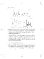
shows a fast HPLC separation where 15 compounds are separated in just one
minute. Figure 1.3b shows the separation power of HPLC by the partial separation
of more than 100 recognizable peaks in just 30 minutes. In Figure 1.4 are illus-
trated comparable separations that were carried out 25 years later. Notice that in
Figure 1.4a, six proteins are separated in 7 seconds, while in Figure 1.4b, c, about
1000 peptides plus proteins are separated in a total time of 1.5 hours. The improve-
ment in Figure 1.4a compared with Figure 1.3a can be ascribed to several factors,
some of which are discussed in Section 1.2. The separation of 1000 compounds in
Figure 1.4b, c is the result of so-called two-dimensional separation (Section 9.3.10): a
first column (Fig. 1.4b) provides fractions for further separation by a second column
(Fig. 1.4c). In this example 4-minute fractions were collected from the first column
and further separated with the second column; Figure 1.4c shows the separation of
fraction 7. The total number of (recognizable) peaks in the sample is then obtained
by adding the unique peaks present in each of the fractions. The enormous progress
made in HPLC performance (Fig. 1.4 vs. Fig. 1.3) suggests that comparable major
improvements in speed or separation power in the coming years are not so likely.
Some other improvements in HPLC since 1979 have been equally significant.
Beginning in the 1980s, the introduction of suitable columns for the separation
of proteins and other large biomolecules [7, 8] has opened up an entirely new
