Introduction to Modern Liquid Chromatography, Third Edition part 14 pps
Bạn đang xem bản rút gọn của tài liệu. Xem và tải ngay bản đầy đủ của tài liệu tại đây (195.08 KB, 10 trang )
86 BASIC CONCEPTS AND THE CONTROL OF SEPARATION
85. J T.Lin,L.R.Snyder,andT.A.McKeon,J. Chromatogr. A, 808 (1998) 43.
86. C. T. Mant and R. S. Hodges, in HPLC of Proteins, Peptides and Polynucleotides,M.
T. W. Hearn, ed., VCH, New York, 1991, p. 277.
87. K. Yanagida, H. Ogawa, K. Omichi, and S. Hase, J. Chromatogr. A, 800 (1998) 187.
88. T. Baczek, R. Kaliszan, H. A. Claessens, and M. A. van Straten, LCGC Europe,13
(2001) 304.
89. V. Spicer, A. Yamchuk, J. Cortens, S. Sousa, W. Ens, K. G. Standing, J. Q. Wilkens, and
O. V. Korkhin, Anal. Chem., 79 (2007) 8762.
90. P. C. Sadek, P. W. Carr, R. M. Doherty, M. J. Kamlet, R. W. Taft, and M. H. Abraham,
Anal. Chem., 57 (1985) 2971.
91. C. F. Poole and S. K. Poole, J. Chromatogr. A, 965 (2002) 263.
CHAPTER THREE
EQUIPMENT
3.1 INTRODUCTION, 88
3.2 RESERVOIRS AND SOLVENT FILTRATION, 89
3.2.1 Reservoir Design and Use, 90
3.2.2 Mobile-Phase Filtration, 91
3.3 MOBILE-PHASE DEGASSING, 92
3.3.1 Degassing Requirements, 92
3.3.2 Helium Sparging, 94
3.3.3 Vacuum and In-line Degassing, 95
3.4 TUBING AND FITTINGS, 96
3.4.1 Tubing, 96
3.4.2 Fittings, 99
3.5 PUMPING SYSTEMS, 104
3.5.1 Reciprocating-Piston Pumps, 104
3.5.2 On-line Mixing, 109
3.5.3 Gradient Systems, 112
3.5.4 Special Applications, 112
3.6 AUTOSAMPLERS, 113
3.6.1 Six-Port Injection Valves, 114
3.6.2 Autosampler Designs, 116
3.6.3 Sample-Size Effects, 119
3.6.4 Other Valve Applications, 122
3.7 COLUMN OVENS, 125
3.7.1 Temperature-Control Requirements, 125
3.7.2 Oven Designs, 126
3.8 DATA SYSTEMS, 127
3.8.1 Experimental Aids, 127
3.8.2 System Control, 129
3.8.3 Data Collection, 129
3.8.4 Data Processing, 130
3.8.5 Report Generation, 130
3.8.6 Regulatory Functions, 130
3.9 EXTRA-COLUMN EFFECTS, 131
Introduction to Modern Liquid Chromatography, Third Edition, by Lloyd R. Snyder,
Joseph J. Kirkland, and John W. Dolan
Copyright © 2010 John Wiley & Sons, Inc.
87
88 EQUIPMENT
3.10 MAINTENANCE, 131
3.10.1 System-Performance Tests, 131
3.10.2 Preventive Maintenance, 138
3.10.3 Repairs, 143
3.1 INTRODUCTION
Equipment design for modern HPLC is in a mature state. With certain exceptions
(e.g., high-pressure applications, Section 3.5.4.3), major changes in equipment design
and features are not often encountered. While small changes from one model to
its replacement continue to improve the reliability of HPLC equipment, the rapid
obsolescence of HPLC equipment that was once a concern is no longer an issue for
most applications.
Analysts beginning their use of HPLC often ask which system or manufacturer
is ‘‘best.’’ Today there is less distinction between HPLC systems than in the past,
and it can be safely said that there are no ‘‘bad’’ HPLC systems currently on the
market. This means that a features-and-benefits approach to equipment selection
often gives way to choices based on local service and support provided by the
equipment vendor. Users in the past often would select specific equipment modules
from different vendors and, in a mix-and-match approach, would design their
own ‘‘ideal’’ HPLC system. Today this is not common, partly because of the
equivalent performance of components between manufacturers, and partly because
of the interdependence of the various modules. Usually components chosen from
a single manufacturer will work together better than will modules from several
manufacturers combined into a single system. Thus the pump, autosampler, and
column oven usually are obtained as a unit or as compatible components from a
single manufacturer.
The detector may be obtained from a second manufacturer, especially for
specialty detectors, such as MS/MS (Section 4.10). Because the major data-system
manufacturers often include the ability to control equipment from other vendors, the
data system may be chosen from another manufacturer than the pumping compo-
nents. However, when maintenance, training, repair, and equipment compatibility
are considered, most laboratories purchase as many components of the HPLC system
as possible from a single vendor and stay with a single manufacturer if multiple
HPLC systems are operated in a single facility. An alternative practice is used in
some large laboratories, especially those that transfer methods to other sites (Section
12.7). In such cases equipment is selected from several manufacturers in order to
allow comparison of method performance on different instruments. This approach
helps highlight potential equipment-dependent method-transfer problems that can
be addressed prior to transfer of the method to a second laboratory.
3.2 RESERVOIRS AND SOLVENT FILTRATION 89
Figure 3.1 HPLC system diagram.
The essential components of an HPLC system are shown in Figure 3.1. Mobile
phase is drawn from a reservoir into a pump, which controls the flow rate and
generates sufficient pressure to drive the mobile phase through the column. An
injector or autosampler is used to place the sample on the column without stopping
the pump flow. The separation takes place in the column, which generally resides
inside a column oven. The detector responds to changes in analyte concentration
during the run. A data system monitors the detector output and provides data
processing for both graphic and tabular output of data. A system controller (often
combined with the data system) directs the functions of the various modules.
The HPLC system may comprise a group of individual components (often
referred to as a ‘‘modular’’ system), or the components may be combined within
a single cabinet as an ‘‘integrated’’ system. Because of the precious nature of
laboratory bench space, modular systems usually are designed to enable stacking of
components for a small footprint, similar to that of an integrated system. In addition
to systems designed for analytical applications, HPLC systems may be specially
designed for low-flow (micro), high-flow (preparative), or high-pressure applications
(Sections 3.5.4 and 15.2). The majority of analytical methods rely on UV detection,
but many other detectors are available for specialized applications (Chapter 4).
In this chapter the various components of the HPLC system are discussed,
with the exceptions of the detector (Chapter 4) and application of the data system
(Chapter 11). Unless stated otherwise, commercially available equipment is assumed
in every case.
3.2 RESERVOIRS AND SOLVENT FILTRATION
Mobile-phase reservoirs (Fig. 3.2) are simple yet essential parts of the HPLC system.
For isocratic applications using premixed mobile phase, only a single reservoir is
90 EQUIPMENT
vent
reservoir
inlet-line frit
(b)
(a)
Figure 3.2 Mobile-phase reservoir.
needed. When isocratic mobile phases are blended online or for gradient applications,
more than one reservoir is used. Mobile phases must be free of particulate matter,
so mobile-phase filtration may be required prior to filling the reservoir.
3.2.1 Reservoir Design and Use
Most reservoir containers (Fig. 3.2a) are made of glass, although some applications,
such as the determination of Na
+
ions by ion chromatography, require a glass-free
system. Laboratory glassware (e.g., Erlenmeyer flasks), heavy-walled glass bottles, or
the glass bottles in which the solvents are shipped are the common reservoirs. Some
equipment manufacturers supply reservoirs specifically designed for their equipment.
Besides inertness to the mobile phase, cleanliness is the most important reservoir
requirement. Glassware should be washed on a regular basis (e.g., weekly), using
standard laboratory dishwashing techniques. A cover of some sort should be used
to keep dust from entering the reservoir and to minimize evaporation of the mobile
phase, but the reservoir should not be so tightly capped that a vacuum forms when
mobile phase is pumped out. A threaded cap with an oversized hole (Fig. 3.2a)
for the mobile-phase inlet line or a piece of aluminum foil crimped around the top
of the reservoir are the most popular closure techniques and allow rapid pressure
equalization when mobile phase is pumped out. The use of polymeric laboratory
film products (e.g., Parafilm
®
) to cover the reservoir should be avoided, since some
mobile phases may extract components that can contaminate the system.
An inlet-line frit (Fig. 3.2a,b) is used at the inlet end of the tubing that connects
the reservoir and the pump. The frit acts as a weight to keep the inlet tubing at the
bottom of the reservoir, but its primary function is to provide backup filtration to
remove particulate matter, such as dust, that might enter the reservoir. Since it is
not the primary solvent filter, it should not restrict solvent flow to the pump. A frit
3.2 RESERVOIRS AND SOLVENT FILTRATION 91
porosity of ≥10 μm is recommended so that solvent can flow freely through the
inlet-line frit. This can be confirmed with a siphon test. Disconnect the tube fitting
at the pump inlet (high-pressure mixing systems) or solvent proportioning module
(low-pressure mixing); if solvent is not flowing freely, start a siphon flowing with a
pipette bulb. A good rule of thumb is that the flow through the siphon should be
≥10× the required flow rate when the solvent reservoirs are located
>
50 cm above
the point of measurement. For example, if flow rates of 1 to 2 mL/min are typically
used, the siphon test should supply
>
20 mL/min of solvent. Generally, flow rates
of
>
50 mL/min are observed under these conditions. If the siphon delivery is too
slow, replace the frit and/or clear any blockage in the tubing. In use, the reservoir
should be located higher than the pump inlet (e.g.,
>
50cm)soastoprovidea
positive-pressure feed of solvent to the pump for more reliable pump operation.
There are many designs of inlet-line frits available, and these are made of
stainless-steel, ceramic, PEEK, and other materials that are inert to the mobile phase.
One popular design is sketched in Figure 3.2b, in which the intake portion of the
frit is on the bottom rather than the sides. This ‘‘last drop’’ design enables the use of
more mobile phase in the reservoir before it must be replenished.
3.2.2 Mobile-Phase Filtration
The operation of several parts of the HPLC system can be compromised if particulate
matter is present. These parts include proportioning valves, check valves, tubing,
and column frits. For this reason it is important to use a particulate-free mobile
phase. If prefiltered (i.e., HPLC-grade) solvents are not available, the mobile-phase
components should be filtered prior to adding them to the reservoir. For laboratories
that work in a regulated environment, a standard operating procedure (SOP) should
be written to describe when additional mobile-phase filtration is required and when
it is not.
Use of prefiltered solvents is the simplest way to avoid introducing particulate
matter into the mobile phase. Commercial HPLC-grade solvents are filtered through
submicron filters (generally 0.2 μm) prior to packaging. HPLC-grade water prepared
in the laboratory (e.g., Milli-Q water purification) is passed through a final 0.2-μm
filter as the last step in purification. If only HPLC-grade liquids are used in the
mobile phase, it is common practice not to perform any additional filtration prior to
use. However, if non–HPLC-grade reagents or any solid reagents are added to the
mobile phase (e.g., phosphate buffer), it is wise to filter all mobile-phase mixtures
prior to use.
Mobile phases can be easily filtered with a vacuum-filter apparatus, such as
that shown in Figure 3.3. A membrane filter (typically ≈0.5-μm porosity) is mounted
on a support frit between the funnel and the vacuum flask. Solvent is poured into the
funnel and collected under vacuum-assisted (e.g., water aspirator) filtration. Filter
manufacturers provide guides to the selection of the proper filter material for each
application. For example, PTFE filters are hydrophobic and work well with pure
organic solvents, such as MeOH or ACN, but are too nonpolar to allow rapid
filtration of water. The seal between the vacuum flask is made with a ground-glass
fitting or an ‘‘inert’’ stopper (e.g., silicone), but it is best not to allow mobile phase
to contact the stopper.
92 EQUIPMENT
vacuum flask
vacuum
filter funnel
support frit
membrane filter
inert
stopper
Figure 3.3 Vacuum apparatus for mobile phase filtration.
3.3 MOBILE-PHASE DEGASSING
The presence of air bubbles in the mobile phase is a common problem in the
operation of an HPLC system. These bubbles can lead to pump-delivery problems
and spurious peaks in the detector output. Most often concern about bubbles can
be eliminated by degassing the mobile phase prior to use.
3.3.1 Degassing Requirements
As long as air remains dissolved in the mobile phase, bubble problems are seldom
encountered. In principle, hand-mixed isocratic mobile phases should be suitable
for use without degassing, but an air-saturated solution may outgas with only a
minor drop in pressure, such as when the mobile phase is pulled through the solvent
inlet-line filter or when it enters the relatively low-pressure region in the detector
cell. For this reason, and for general HPLC operational reliability, degassing of all
solvents used for reversed-phase applications is strongly recommended. Outgassing
is less of a problem with normal-phase HPLC, so degassing may be considered as
optional in such applications. The amount of dissolved gas that must be removed
from the mobile phase will vary with the design of the HPLC pump—some pumps
are very tolerant to dissolved gas, whereas others require thorough degassing for
reliable operation.
Bubble formation can be especially problematic in the case of mobile phases
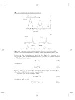
for reversed-phase chromatography (RPC), as illustrated by the data of Figure 3.4.
For example, assume that pure water and pure ethanol are each saturated with
oxygen, as might be the case if the solvents are exposed to air. When the solvents are
blended, the mixture contains an amount of oxygen and solvent that is proportional
3.3 MOBILE-PHASE DEGASSING 93
Figure 3.4 Solubility of oxygen in ethanol. (- - -), Oxygen concentration following mixing of
air-saturated water and ethanol (before release of excess oxygen); (—), saturation concentra-
tion of oxygen in mixture. Adapted from [1].
to the relative concentrations of each solvent (represented by the dashed line in
Fig. 3.4). However, oxygen is seen to be less soluble in a solvent mixture (solid
line in Fig. 3.4), so the mixture is now supersaturated with oxygen. In such cases
oxygen either bubbles out immediately or when it contacts a nucleation site, such as
the rough surface of the solvent inlet-line filter. Although Figure 3.4 shows data for
oxygen, water, and ethanol, the same principle holds for air (comprising primarily
nitrogen and oxygen), buffered water, and other organic solvents, such as acetonitrile
or methanol [1]. These data also suggest that it is not necessary to remove all of
the dissolved air from solution—just enough that the amount of dissolved air in the
mixtures is below the (solid) saturation curve of Figure 3.4.
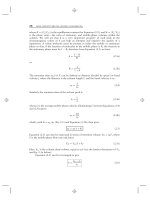
For most applications, degassing is important primarily to improve pump
operation. However, in some cases the presence of dissolved oxygen can degrade
detector performance. It has been reported [2] that UV detection (Section 4.3) as low
as 185 nm is possible if the detector (and acetonitrile/water mobile phase) is purged
with helium to remove oxygen from the optical path of the detector. Under these
conditions the apparent detector-lamp response increased and the baseline noise
was reduced. Even at higher wavelengths, dissolved oxygen in the mobile phase can
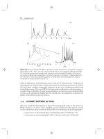
elevate the detector background signal, as can be seen in Figure 3.5a. At 254 nm,
the mobile phase sparged with air gave an increased baseline signal compared
to the mobile phase sparged with helium, presumably because of a change in
refractive index of the air-sparged mobile phase. Under the same conditions, but with
fluorescence detection (Section 4.5), ≈75 % of the signal intensity for naphthalene
was lost (Fig. 3.5b) when the mobile phase was sparged with air instead of helium
[1]. When the electrochemical detector (Section 4.6) is operated in the reductive
mode, dissolved oxygen creates an unacceptable background signal, so oxygen must
be removed from the mobile phase, as by helium sparging (Section 3.3.2). Finally, it is
conceivable that dissolved oxygen might react with some samples during separation.
So it is important to select a degassing technique that addresses both chemical
94 EQUIPMENT
Figure 3.5 Effect of helium sparging on detector response to naphthalene. (a) UV detec-
tion at 254 nm, (b) fluorescence detection at 250-nm excitation and 340-nm emission. He,
mobile-phase sparging with helium begins; air, sparging with air begins. Adapted from [1].
problems (e.g., detector response) and physical problems (e.g., bubbles in the pump)
that may result from the presence of dissolved gas in the mobile phase.
When off-line degassing is used, such as stand-alone helium sparging or vacuum
degassing, the solvent will begin to re-equilibrate with air as soon as the degassing
treatment is stopped. For HPLC systems that are highly susceptible to dissolved gas in
the mobile phase, off-line degassing may not be sufficient. In such cases continuous
helium sparging (Section 3.3.2) or on-line vacuum degassing (Section 3.3.3) are
better choices.
3.3.2 Helium Sparging
Helium sparging is the most effective technique for removing dissolved gas from
the mobile phase [3] (with the exception of refluxing or distillation), and removes
80–90% of the dissolved air. Typically a frit is used to disperse helium (e.g., at
≈5 psi through a sparging frit) in the reservoir. Under these conditions it takes
only one volume of helium to degas an equal volume of mobile phase [4]. This
means that just a few minutes of a vigorous sparging stream will adequately degas
the mobile phase. Helium itself has such a low solubility in HPLC solvents that a
helium-sparged solution is nearly gas free. Excessive sparging of the mobile phase
is undesirable, since it can change the composition of the mobile phase through
evaporation of the more volatile component(s); however, vigorously sparging a RPC
mobile phase for a few minutes is unlikely to cause problems Normal-phase solvents
are much more volatile, so helium sparging of a (blended) mobile phase should be
used cautiously—if at all. Sparging pure solvents prior to on-line mixing poses no
problem, however.
3.3 MOBILE-PHASE DEGASSING 95
3.3.3 Vacuum and In-line Degassing
For most HPLC systems, the application of a partial vacuum to the mobile phase will
remove a sufficient amount of dissolved gas to avoid outgassing problems. Vacuum
degassing for 10 to 15 minutes will remove 60–70% of the dissolved gas [3]. In its
simplest form, some vacuum degassing takes place during solvent filtration, as in
Figure 3.3. This can be enhanced after filtration is complete by replacing the filter
funnel with an inert stopper and applying the vacuum for a few more minutes. Some
users find that placement of the vacuum flask in an ultrasonic cleaning bath during
this process further enhances degassing.
Today in-line (or on-line) degassing is the most popular degassing technique;
most HPLC equipment manufacturers include an in-line degasser as either standard
or optional equipment with new systems. The operation of the in-line degasser
is illustrated in Figure 3.6 for two solvents (A and B; degassers for 1–4 solvents
are available), and it is based on the selective permeability of certain polymeric
tubing to gas. The degasser is mounted before the pump(s) (high-pressure mix-
ing, Section 3.5.2.1; or hybrid systems, Section 3.5.2.3) or proportioning valves
(low-pressure mixing, Section 3.5.2.2). Solvent is passed through a piece of poly-
meric tubing inside a vacuum chamber; the vacuum pulls the dissolved gas passes
through the walls of the tubing; the liquid mobile phase stays inside the tubing (detail
gas-permeable tubing
mobile phase
vacuum
vacuum
dissolved gas
mobile phase
in
in
out
mobile phase
out
B
A
(b)
(a)
Figure 3.6 Diagram of a membrane degassing apparatus for two solvents, A and B.