Introduction to Modern Liquid Chromatography, Third Edition part 19 pdf
Bạn đang xem bản rút gọn của tài liệu. Xem và tải ngay bản đầy đủ của tài liệu tại đây (133.93 KB, 10 trang )
136 EQUIPMENT
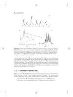
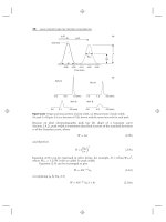
Figure 3.28 Results of a gradient proportioning valve (GPV) test. (a) Gradient proportioning
valve test results; (b) detail showing ±2% allowed difference between plateaus. Baseline is
generated by 50:50 A:B; the remaining plateaus are 90:10 A:C, A:D, B:C, and B:D from left to
right. Solvents: A = B = water; C = D = 0.1% acetone in water.
Table 3.4
Typical System Performance Parameters for Tests of Section 3.10.1
Parameter/Test Typical Specification Typical Acceptance Criteria
Linearity ±1% Visual linearity 5–95% B
Dwell-volume Varies As measured
Step-test (accuracy) ±1% ±1%
GPV
a
test Not specified ≤2% plateau range
b
Flow rate (collect 10 mL at 1 mL/min) ±1% ±2% (±12 sec on 10 mL at
1 mL/min)
Pressure bleed-down from 4000 psi Not specified 15% in 10 min
Retention reproducibility Not specified ±0.05 min
Area reproducibility (10 μL injection) ±0.3% ±1%
a
Gradient proportioning valve.
b
Difference between highest plateau and lowest plateau when C or D solvent is blended with A- or
B-solvent, as in Figure 3.28.
the acceptance criterion is set to ±2%, since the combination of measurement errors
(volumetric glassware) and the timing start/stop errors will add somewhat to the
overall measured error.
Pressure Bleed-Down. Malfunctioning check valves and worn pump seals often
show up as deviations in expected values of mixing accuracy, gradient linearity, and
flow rate. An additional test of the outlet check valves can be made with a pressure
bleed-down test. For this test the outlet tubing from the pump is blocked (by a union
and a plug). The high-pressure shutoff limit for the pump is set near its maximum
3.10 MAINTENANCE 137
value, for example, 5000 psi (350 bar) for a system capable of 6000 psi (400 bar).
The pump is then turned on and allowed to shut off at the upper pressure limit. The
maximum pressure is recorded, and 10 minutes later the pressure is recorded again.
A pressure drop of ≤15% indicates that the check valves are working properly. A
larger drop suggests that the outlet check valve(s) should be cleaned or replaced
or that the pump seal(s) should be replaced if no outlet check valve is used (e.g.,
accumulator-piston pump, Section 3.5.1.2). A pressure drop to atmospheric pressure
over the 10-minute test is more indicative of a leaky fitting.
Retention Reproducibility. A check of retention reproducibility is an overall
check of on-line mixing and pump performance. Although this check can be done
with any sample, it is wise to use a sample that can be formulated easily under
conditions that can be reproduced at any time. This allows an independent check
of system performance to be made for a specific method, and it is a good tool for
troubleshooting. Example test conditions are listed in Table 3.5. It is important
to use a sample concentration such that the peak is within the detector’s linear
range and is sufficiently large that baseline noise does not affect the precision of the
measurements. For example, a sample that generates a peak height of 0.1 to 0.8 AU
would be a good choice for UV detection. Retention-time variation of no more than
≈0.05 min (1 S.D.) is acceptable for six replicate injections. Larger variations are an
indication of problems. If the other performance tests prove to be okay, but retention
reproducibility is poor, leaks or air bubbles are the most likely problem sources. An
alternative test, especially if the system is used only for isocratic methods, is to run
the retention test under the isocratic conditions listed in Table 3.5 (80% B).
Table 3.5
Retention-Time and Peak-Area Test Conditions
Parameter Value
Flow rate 1.5 mL/min
Column C
18
, 150 × 4.6 mm, 5 μm
Temperature 35
◦
C
Detection 280 nm UV
Mobile phase A Water
Mobile phase B Methanol
Gradient/isocratic 5–95% B in 20 min
a
/80% B
b
Equilibration time 10 min
Sample 5 μg/mL 1-chloro-4-nitrobenzene
c
Injection volume 10 μL
Retention (typical) gradient/isocratic 14 min
a
/3 min
b
(with V
D
= 2.2mL
d
)
a
Gradient test conditions.
b
Isocratic test conditions; adjust as necessary for 2 < k < 10.
c
Other nonpolar aromatic compounds (e.g., toluene, methyl benzoate) can be used.
d
For other values of the dwell-volume V
D
; gradient retention times will change by the difference in
dwell-volumes divided by the flow rate (1.5 mL/min).
138 EQUIPMENT
Peak-Area Reproducibility. The same chromatograms run for retention repro-
ducibility can be used to determine peak-area reproducibility, which is primarily a
measure of the autosampler’s performance. The variation in peak areas should be
<1% RSD based on six injections. Most modern autosamplers will generate values
of ≤0.5% RSD for injection volumes of ≥5 μL when operated under standardized
conditions (e.g., those of Table 3.5). Poor area reproducibility usually can be traced
to an autosampler problem. Peak-area reproducibility should be checked for both
the isocratic and gradient operation; similar results should be obtained under both
conditions.
New-Column Test. Repeating the column manufacturer’s test procedure on a
new column is a quick procedure to show that the HPLC hardware is working
properly. This test should be done as part of the operational qualification (OQ) or
performance qualification (PQ) testing (Section 3.10.1.1) to show that the system
is functioning well before its first use. The new-column test also serves as a tool in
the ‘‘divide-and-conquer’’ strategy (Section 17.3.1) of problem isolation. Just install
a new column and repeat the manufacturer’s performance test. The test conditions
should be similar to the isocratic conditions listed in Table 3.5, and should be listed
in the column test sheet included with the column literature. If the test results are
within ≈10% of the column manufacturer’s tests (retention times, plate number),
the system is working well—the flow rate, column temperature, and mobile-phase
composition are correct, and extra-column effects are minimal. (It is rare to obtain
a plate number as large as that reported in the manufacturer’s test; their column
testing systems are optimized for column performance, not routine operation as in
a user’s laboratory.)
3.10.2 Preventive Maintenance
A good way to improve the reliability of an HPLC system is to anticipate and
prevent problems before they occur. Problems with HPLC systems can result from
normal wear of components or from the way the system is used. Many problems can
therefore be minimized by performing periodic maintenance so that normal-wear
items are serviced or repaired before they fail. In addition there are a number of
simple laboratory practices that can be undertaken to minimize user-caused system
failure.
3.10.2.1 Periodic Maintenance
Regular cleaning and/or component replacement will help make the HPLC system
work more reliably. Some of these periodic maintenance tasks are listed in Table 3.6.
The recommended frequency of the various actions is typical for HPLC systems used
several times a week; the experience in each laboratory may vary from these
recommended intervals. The important concept is that a disciplined approach be
taken so that every instrument receives regular maintenance. For further details on
the parts and modules mentioned below, consult the descriptions in the first part of
this chapter.
Reservoir. The reservoir that contains the aqueous solvent (A-solvent) should
be cleaned and replenished, so that microbial growth does not occur. Replacement
3.10 MAINTENANCE 139
Table
3.6
Recommended Maintenance Intervals
Item Action Frequency
a
Reservoir Replace buffer, wash reservoir Weekly
Replace organic, wash reservoir Monthly
Filter mobile phase Every batch
Replace inlet-line frit 6 months
Degas mobile phase Daily
Tubing and fittings Inspect for leaks Weekly
Pump(s) Sonicate or replace check valves As needed
Replace pump seal(s) 6 months
Flush to remove buffers Daily
Inspect for leaks Daily
Autosampler Replace wash solvent and clean
Reservoir
Weekly
Replace valve rotor seal See manufacturer’s
recommendations
Replace needle seal 6 months
Inspect for leaks Daily
Column oven Calibration check Annually
Inspect for leaks Daily
Detector Inspect for leaks Weekly
Additional detector checks See detector manual
Waste container Check capacity; empty Daily
Data system Per experience
LC system System check 6 months
LC method System suitability Daily
a
Mayvarybasedonfrequencyofuse,performancehistory,orSOP.
of the A-reservoir and its contents on a weekly basis should avoid this, although
some laboratories stretch this to two weeks. It is a good idea never to ‘‘top off’’ the
aqueous solvent, but instead to use a clean reservoir for each new batch of aqueous
solvent. The organic reservoir (B-solvent) has a longer cleaning and replacement
cycle, because the probability of microbial growth in
>
30% organic is considerably
diminished compared with the aqueous phases. If the A- or B-solvent comprises only
HPLC-grade solvents, mobile-phase filtration is not required; otherwise, all mobile
phases should be filtered through a membrane filter of ≤0.5-μm porosity. The
inlet-line frit can be an inadvertent source of re-inoculation of the reservoir contents
once it becomes contaminated. The frit is inexpensive, so it should be replaced every
six months as a precautionary measure. Mobile-phase degassing is one of the easiest
ways to improve system reliability, so all solvents used for reversed-phase HPLC
should be degassed (Section 3.3).
140 EQUIPMENT
Tubing and Fittings. If tubing and fittings are properly assembled, they should
work indefinitely without problems. However, leaks do occur occasionally, so it is a
good idea to check all tubing and fittings for leaks once a week. A drop of moisture
or a small bit of white buffer residue may be the only sign of a leak. If a leak is found,
the pump should be shut off, the fitting tightened, and the pump turned back on
again. When PEEK fittings and/or tubing are used, the tube end should be reseated
in the fitting port prior to tightening the fitting. Sometimes PEEK tubing will slip
in the fitting when it is tightened under pressure, so the pump should be turned off
during this operation.
Pumps. Sticky or leaky check valves are the most common pump problem
in most systems. This is indicated most commonly by system-pressure fluctuations.
Many times a leaky check valve can be reconditioned by sonication in MeOH for a
few minutes. Prior to sonication, it is best to inspect the check valve to ensure that
the components will not fall out and get mixed up. If the valve requires reassembly,
dust-free gloves should be used, so as to avoid recontamination of the check valve.
(See Section 17.2.5.4 for additional information on check-valve sonication.) Pump
seals may last for a year or more, but they are inexpensive and when pump-seal
failure occurs, other problems may arise, such as blocked frits. For this reason it
is prudent to replace the pump seals twice a year, that is, before significant wear
occurs. Buffers left in the pump when it is not used can precipitate and leave abrasive
deposits that increase pump-seal wear or cause check-valve problems. It is a good
practice to flush all buffers out of the HPLC system before shutting it off for more
than an hour or two. If the system must be ready to run at a moment’s notice (‘‘stat’’
conditions), the pump can be set to its minimum flow rate (e.g., 0.1 mL/min), so
the mobile phase is always flowing. As with tubing and fittings, pump leaks occur
periodically, so it is a good idea to inspect the pump for leaks each day during
startup.
Autosampler. Just as the mobile phase and the reservoirs need to be cleaned
or replaced to avoid microbial contamination, the autosampler wash-solvent and
its reservoir should be replaced periodically. If an aqueous wash-solvent is used, it
should be replaced and the reservoir cleaned each week; if organic solvent is used,
monthly service should suffice. The injector rotor seal has a long life—100,000
cycles or more if treated properly. Check the manufacturer’s recommended service
interval in the preventive maintenance section of the operator’s manual. The needle
seal will wear with continued use. If there are no other guidelines in the operator’s
manual, replacement of the needle seal every six months will help to avoid problems.
The autosampler is the component of the HPLC system that is most likely to leak; it
is wise to inspect it daily for leaks.
Column Oven. The column oven should be a trouble-free component. The oven
calibration should be checked when the oven is first installed, then on an annual
basis. A flow-through thermocouple can be used to check the temperature of the
mobile phase exiting the column as a check of the oven temperature and temperature
equilibration within the column. During system startup each day or when a new
method is started, the column endfittings should be checked for leaks.
3.10 MAINTENANCE 141
Detector. HPLC detectors operate at pressures significantly lower than the
column, so leaks at the detector are less common than elsewhere. However, a weekly
check is wise. Other detector checks will vary depending on the detector; consult the
detector manual for more information.
Waste Container. The waste container is a system component that is easy to
overlook. It is wise to check it daily to ensure that it has sufficient capacity for the
day’s runs. Placement of the waste container in a plastic dishpan or other safety
container will help protect against spills when the inevitable overflow occurs.
HPLC System-Check. The system performance checks described in
Sections 3.10.1.2 and 3.10.1.3 should be performed once or twice a year. A
semiannual check will often catch pending problems that might occur if the check is
done on an annual basis. Check the system on a yearly basis if a semiannual check
cannot be justified.
HPLC Method-Check. Before samples are run with an analytical method, a
system suitability check should be made. This may be the most important test that
one can perform for an HPLC system because it shows that both the system and
method are suitable for carrying out the desired analysis.
3.10.2.2 Suggestions for Routine Applications
To obtain high-quality data, the HPLC system must perform in a reliable and repro-
ducible manner. This section lists and reviews some additional tips and techniques
that will help ensure high quality results.
Reagent Quality. Gradient elution tends to concentrate nonpolar impurities in
the A- and B-solvents at the head of the column, followed by their release as the
gradient progresses. These impurities can show up as peaks in both blank and sample
runs (e.g., Fig. 17.12 and Sections 17.2.5.9, 9.6.2). For this reason it is essential to
use HPLC-grade reagents for gradient work. Lower quality reagents may be suitable
for isocratic applications, but even the most minor impurities can cause problems
with gradient elution. For best results one should use only HPLC-grade reagents
for all HPLC work. Aqueous reagents and buffers should be discarded frequently
(e.g., weekly) to avoid contamination by microbial growth. Water impurities can be
especially problematic.
System Cleanliness. As important as reagent quality in minimizing artifactual
peaks is maintaining a clean instrument. The recommendations of Section 3.10.2.1
(reservoirs and pumps) should be followed. Spills, leaks, and other potential sources
of contamination should be cleaned up promptly.
Degassing. Although some HPLC systems will operate without degassing
the mobile phase, every system will operate more reliably with degassed solvents
(Section 3.3). Trapped air bubbles and solvent outgassing are common problems
that can be largely avoided by solvent degassing. It is a good idea to purge the
pump(s) and solvent inlet lines daily by opening the purge valve(s) and operating the
pump at an elevated flow rate (e.g., 5 mL/min) for a few minutes to remove any air
bubbles.
142 EQUIPMENT
Dedicated Columns. Each analytical method should have a column dedicated
to that method. It is not a good idea to share columns between methods, since
peaks that are not of concern in one method (e.g., late-eluting peaks) may cause
interferences in a second method. Sample components may change the selectivity or
degrade the column for one method but not another.
Equilibration. Prior to each run, the column should be equilibrated to the same
extent as the other runs in the run sequence. Complete equilibration may or may
not be necessary for gradient methods (Section 9.3.7).
Priming Injections. Some methods give better results if several ‘‘priming’’
injections are made before the first sample is injected. These injections of standards
or mock samples can help saturate slowly equilibrating active sites on the column
so that more reproducible separations can be obtained. Priming injections are more
often useful for separations of biological samples (Section 13.3.1.4). Sometimes the
system suitability injections serve as priming injections.
Ignore the First Injection. Because some methods require a priming process
and the first injection may be equilibrated differently than subsequent injections, it
is best to avoid use of the first injection for quantitative analysis. The second and
subsequent runs will be more reliable than the first injection; a preceding system
suitability test (see following) also serves this purpose.
System Suitability. Many methods that run under the oversight of regulatory
agencies (FDA, EPA, OECD, USP, etc.) will require a system suitability test prior
to sample analysis. System suitability serves as a confirmation that the equipment
and analytical method are operating in a fashion that will produce reliable results.
Requirements for system suitability tests vary, so the regulatory guidelines should be
consulted to help select appropriate tests (Section 12.3). Many workers use retention
time and area reproducibility, peak response (detection sensitivity), peak width,
peak tailing, resolution, and column pressure, either alone or in combination, as
part of the system suitability test. The system suitability sample may be a diluted
pure standard, a mock sample in extracted matrix, or some other sample selected
to demonstrate system performance. The important concept is to select system
suitability samples that test the ability of the method to perform its desired function.
Whether or not a system suitability test is required, it is wise to run such a test prior
to routine analysis, even if it is just an injection of a standard to see if the retention
and peak size are as expected.
Standards and Calibrators. For quantitative analysis (Chapter 11), the response
of unknown samples is compared to the response for standards of known concen-
tration. The range of standard concentrations, number of replicates, and sequence
of injection may depend on the specific application. Either external or internal
standardization may be used. In any event, at least one standard should be injected
prior to the analysis of unknown samples, to ensure that the analytical method is
working properly before potentially valuable samples are injected.
3.10 MAINTENANCE 143
Table
3.7
Repair Recommendations
User Level Typical Repairs
Novice/operator Replace mobile phase, inlet-line filter, in-line filter, guard column, column
Experienced Check valves, pump seals, proportioning-manifold replacement, injector rotor,
detector lamp, tubing and fittings
Factory-trained Proportioning-manifold repair, electronics, repairs involving module
subassemblies, detector flow cell
3.10.3 Repairs
Sooner or later, no matter how much preventive maintenance is practiced, problems
will be encountered on every HPLC system. Chapter 17 is dedicated to troubleshoot-
ing. In this section, some of the more philosophical aspects of instrument repair are
considered.
3.10.3.1 Personnel
Some laboratories rely completely on a service contract from the equipment man-
ufacturer for all maintenance and repairs, whereas other laboratories perform all
these tasks themselves. Most laboratories, however, rely on something between these
two extremes. Even in the case of a 100% service-contract arrangement, there are
repairs that make sense to accomplish with laboratory staff—for time savings, if
nothing else. It is a good idea to have a plan in place that determines what repairs
are to be made by which personnel. Some recommendations are listed in Table 3.7
and discussed in Section 3.10.3.3.
3.10.3.2 Record Keeping
Laboratories working under the oversight of regulatory agencies may be required to
keep maintenance and repair records, but even laboratories for which such records
are not required should maintain some level of equipment records. One of the
simplest record-keeping techniques is to prepare a three-ring binder with sections
for different maintenance activities and records. A separate binder is kept with each
HPLC system where it can be referenced easily and is most likely to be used during a
maintenance session. It is convenient to organize this record book in three sections:
System Configuration. A record should be made of all the components in
a given system configuration, including the model and serial numbers of each
component. As changes are made, a fresh copy can be completed. This will facilitate
communications with the instrument vendors when service is needed, and will help
confirm for regulatory auditors the specific system configuration used with a specific
sample.
144 EQUIPMENT
Maintenance Records. Repair records can be simplified if a template is made
that contains blanks for the who, what, why, when, and how questions of a
maintenance session. Several blank copies of these pages can be kept in the notebook
so that one is available to complete for each maintenance session. Once a year,
or after a number of sessions, these pages can be sorted into failure categories
(e.g., pump-seals, check valves) and can serve to help develop a system-specific or
laboratorywide preventive maintenance program.
System Checks. A third section can contain the records from the periodic
instrument system checks (Sections 3.10.1.2, 3.10.1.3). With a readily available
historic record, trends from one system check to another can be tracked. These also
can provide data that help establish preventive maintenance programs.
Record-keeping technologies could also be used. Computer databases or elec-
tronic notebooks are two good options. But, it is important that they are sufficiently
convenient, so that data can be easily entered at the time of maintenance or repair;
otherwise, valuable records will be lost.
3.10.3.3 Specific Repair Recommendations
Table 3.7 summarizes various repairs that are appropriate for users of different skill
levels:
Novice/Operator. Personnel just learning how to run an HPLC system, or
workers in a routine environment that ‘‘just’’ run samples, may have limited skills
or authority to make repairs. However, little training is needed to replace mobile
phases, filters, guard columns, and columns. A system of double-checking or sign-off
by a second person will help avoid errors in such activities.
Experienced. As the user gains experience, additional troubleshooting and
maintenance skills will be developed. Some people have a natural tendency to
become more skilled than others, but most workers can learn how to change
check valves, pump seals, and tubing and fittings. More complex problems, such
as replacement of detector lamps or low-pressure gradient-proportioning manifolds,
can be reserved for more skilled workers.
Factory-Trained. Certain activities should be reserved for specially trained per-
sonnel. These may be normal laboratory workers with an excellent troubleshooting
and maintenance aptitude, a service group within the company, or a technician con-
tracted from the instrument manufacturer. Electronics problems generally require
advanced skills and/or equipment to fix. Other problems that involve disassembly of
modules or repair of components that are delicately tuned—such as proportioning
valves—may also call for special training.
REFERENCES
1. S. R. Bakalyar, M. P. T. Bradley, and R. Honganen, J. Chromatogr., 158 (1978) 277.
2. S. van der Wal and L. R. Snyder, J. Chromatogr., 255 (1983) 463.
REFERENCES 145
3. J. N. Brown, M. Hewins, J. H. M. van der Linden, and J. H. M Lynch, J. Chromatogr.,
204 (1981) 115.
4. L. R. Snyder, J. Chromatogr. Sci., 21 (1983) 65.
5. J. Thompson, personal communication, 2008.
6. (Valco Instruments).
7. (Upchurch Scientific).
8. J. W. Batts, IV, All About Fittings, Upchurch Scientific, Oak Harbor, WA, 2003.
9. Y. Ishihama, J. Chromatogr. A., 1067 (2005) 73.
10. J. Hernandez-Borges, Z. Aturki, A. Rocco, and S. Fanali, J. Sep. Sci., 30 (2007) 1589.
11. S. Stearns, personal communication, 2008.
12. Technical Notes 5, Rheodyne, Dec. 1983.
13. (Rheodyne).
14. O. Abreu and G. D. Lawrence, Anal. Chem., 72 (2000) 1749.
15. R. G. Wolcott, J. W. Dolan, L. R. Snyder, S. R. Bakalyar, M. A. Arnold, and J. A.
Nichols, J. Chromatogr. A, 869 (2000) 211.
16. J. W. Dolan, J. Chromatogr. A, 965 (2002) 195.
17. P L. Zhu, L. R. Snyder, J. W. Dolan, N. M. Djordjeveic, D. W. Hill, L. R. Sander, and
T. J. Waeghe, J. Chromatogr. A, 756 (1996) 21.
18. Guidance for Industry: Part 11, Electronic Signatures—Scope and Application,
(2003).
19. J. J. Gilroy and J. W. Dolan, LCGC, 22 (2004) 982.
20. L. R. Snyder and J. W. Dolan, High-Performance Gradient Elution, Wiley, Hoboken,
NJ, 2007.