Introduction to Modern Liquid Chromatography, Third Edition part 22 potx
Bạn đang xem bản rút gọn của tài liệu. Xem và tải ngay bản đầy đủ của tài liệu tại đây (215.74 KB, 10 trang )
166 DETECTION
210 220 230 240 250 260 270 280
Wavelength (nm)
Absorbance
(b)
X
Y
X (260 nm)
Y (260 nm)
X + Y (260 nm)
(a)
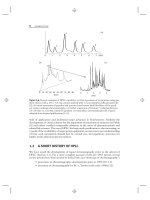
Figure 4.12 Illustration of spectral deconvolution of analytes. (a) Hypothetical chro-
matograms for individual injections of X and Y at 260 nm shown with combined response
X + Y at 260 nm; (b) spectra for X and Y.
ratio across the peak. The same dataset collected at 240 and 280 nm could be
used to determine peak purity by calculation of the 240/280 ratio at every point
across the peak. If the peak were pure X or Y, the ratio would be constant,
whereas if the mixture of Figure 4.12a were present, the ratio would be
>
1when
X was predominant and <1whenY was the major compound. The nonconstant
nature of the ratio would indicate the presence of a peak mixture, even though the
peaks overlapped chromatographically and appeared as a single peak at 260 nm.
Peak-purity algorithms compare the consistency of the spectrum across the entire
peak and in some cases can identify the presence of minor impurities (e.g., <1%)
that are eluted under the tail of the major peak. For additional examples of the
determination of peak purity by DAD, see [20, 21] or the detector manufacturer’s
literature (e.g., [22]).
4.4.4 General UV-Detector Characteristics
Table 4.5 summarizes the general characteristics of UV detectors. UV detectors are
ideal for use with gradient elution; many common, UV-transmitting solvents are
available in HPLC grade for use as mobile phases (Tables I.2 and I.3 of Appendix I).
The UV detector is very useful for the trace analysis of UV-absorbing solutes, but its
widely varying response for different solutes can be a disadvantage if the compound
of interest does not absorb in the UV (or visible) region. UV detectors are reliable
and easy to operate, and are particularly suitable for use by less-skilled operators.
4.5 FLUORESCENCE DETECTORS 167
Table
4.5
UV-Detector Characteristics
Capable of very high sensitivity (for samples that absorb in the UV)
Good linear range (
>
10
5
)
Can be made with small cell volumes to minimize extra-column band broadening
Relatively insensitive to mobile-phase flow and temperature changes
Very reliable
Easy to operate
Nondestructive of sample
Widely varying response for different solutes
Compatible with gradient elution
Detection wavelength can be selected
Internal troubleshooting and calibration checks are common
Built-in test procedures that can be carried out at detector startup identify many
potential detector problems and can provide automatic wavelength calibration.
The background, or baseline absorbance, of UV detectors can increase with
continued use. This usually indicates that the cell windows have become dirty and
need cleaning or replacement. Regular detector-cell flushing (as when the column is
flushed) and sample cleanup can make more thorough cell cleaning a rarity. Lamp
life, a concern in the past, is seldom an issue today. Useful lifetimes of
>
2000 hr are
common, and internal circuitry monitors lamp performance and can alert the user
when the lamp output has deteriorated. Although the linear response range of UV
detectors may be
>
2 AU, according to manufacturer’s specifications, most analysts
try to operate the detectors at <1 AU for best results. Stabilizing the flow-cell
temperature through thermostatting or use of a capillary-tubing heat exchanger
helps to reduce noise and drift from flow rate or temperature changes.
Figure 4.13a shows an example chromatogram for the determination of
derivatized roxithromycin (ROX) in human plasma by UV detection at 220 nm [23].
An internal standard, erythromycin (IS), was added to 50 μL of plasma followed
by solid-phase-extraction sample cleanup and derivatization with 9-fluorenylmethyl
chloroformate (FMOC-Cl). With UV detection at 220 nm, the method could monitor
plasma concentrations of ROX but was unable to reach the LLOQ of <1 μg/mL
necessary for pharmacokinetic studies. (See discussion of Section 4.5 for comparison
of the UV response of Fig. 4.13a for this sample to the fluorescence response of
Fig. 4.13b.)
4.5 FLUORESCENCE DETECTORS
Fluorescence detectors are very sensitive and selective for solutes that fluoresce when
excited by UV radiation. Sample components that do not fluoresce do not produce
a detector signal, so sample cleanup may be simplified. For example, a simple
acetonitrile/buffer extraction allowed detection of as little as 30 pg of (naturally
168 DETECTION
Time
(
min
)
IS (area = 951)
ROX (area = 1901)
IS (area = 961)
ROX (area = 609)
UV absorbance (220 nm)Fluorescence (255 nm ex/315 nm em)
(a)
(b)
UV
fluorescence
501015
501015
Figure 4.13 Chromatogram for the determination of roxithromycin (ROX) in human plasma
by (a) UV detection at 220 nm, and (b) fluorescence detection (excitation 255 nm, emis-
sion 315 nm). Retention: ROX (10.7 min), internal standard erythromycin (5.1 min), both
cleaned up by solid-phase extraction and derivatized with 9-fluorenylmethyl chloroformate
(FMOC-Cl). Adapted from data of [23].
fluorescing) riboflavin in food products by HPLC with fluorescence detection [24].
Fluorescent derivatives of many nonfluorescing analytes can also be prepared (e.g.,
[25]), and this approach can be attractive for the selective detection of compounds
for which sensitive or selective detection methods are otherwise not available.
A schematic of a fluorescence detector is shown in Figure 4.14. The light
source usually is a broad-spectrum UV lamp, such as the deuterium lamp used in
UV detectors, or a xenon flash lamp. The excitation wavelength is selected by a filter
or monochromator, and it illuminates the sample as it passes through the flow cell.
When a compound fluoresces, the desired emission wavelength is isolated with a
filter or monochromator and directed to a photodetector, where it is monitored and
converted to an electronic signal for data processing. Because fluorescence is emitted
in all directions, it is common to monitor the emitted light at right angles to the
incident light—this simplifies the optics and reduces background noise. The least
4.5 FLUORESCENCE DETECTORS 169
lamp
filter or
monochromator
photocell
sample in
sample out
Figure 4.14 Schematic of a fluorescence detector. Dashed lines show optical path.
expensive fluorometers use filters to select both excitation and emission wavelengths,
whereas the most expensive use two monochromators (allowing a wide choice for
both excitation and emission wavelengths). Remember, the fluorescence process is
not 100% efficient, so energy is lost. This means that the emission wavelength
always must be at lower energy (higher wavelength) than the excitation wavelength.
For many samples, the fluorescence detector is 100-fold more sensitive than
UV absorption—and is one of the most sensitive HPLC detectors. In other cases the
sensitivity advantage of fluorescence over UV detection may be smaller but adequate
for the task at hand. A comparison of the detector response to roxithromycin (ROX)
by fluorescence and UV is shown in the RPC separations of Figure 4.13 [23]. ROX
does not fluoresce naturally, so derivatization (9-fluorenylmethyl chloroformate
[FMOC-Cl]) of the sample and internal standard (IS) was used to enable detection
by fluorescence. When comparing the UV response (Fig. 4.13a) to fluorescence
(Fig. 4.13b), the fluorescence response for the derivatized IS is approximately the
same as the UV response, but the derivatized ROX peak response tripled with
fluorescence detection. The baseline noise was approximately the same for both UV
and fluorescence. This increase in response by the fluorescence method was adequate
to reduce the LLOQ to <1 μg/mL of ROX in human plasma, which was required
for pharmacokinetic studies.
Because of its high sensitivity the fluorescence detector is particularly useful
for trace analysis, or when either the sample size is small or the solute concentration
is extremely low. The linear dynamic range of the fluorescence detector usually is
smaller than that of UV detectors, but it is more than adequate for most trace
analysis applications. While the dynamic range (the range over which a change
in sample concentration produces a change in the detector output) of fluorescence
detectors can be fairly large (e.g., 10
4
), the linear dynamic range may be restricted
for certain solutes to relatively narrow concentration ranges (as low as 10-fold). For
all quantitative analyses using the fluorescence detector (or any other detector, for
that matter), the linear range should be determined through the use of appropriate
calibration (Section 11.4.1).
In comparison to other detection techniques, fluorescence generally offers
greater sensitivity and fewer problems with instrument instability (e.g., from temper-
ature and flow changes). If solvents and mobile-phase additives free of fluorescing
materials are used, the fluorescence detector can be used with gradient elution. The
major disadvantage of the fluorescence detector is that not all compounds fluoresce.
170 DETECTION
0
Time (min)
He Heair
Fluorescence
Figure 4.15 Fluorescence quenching of naphthalene by dissolved oxygen in the mobile phase.
Mobile phase sparged with helium (He) or air, as shown. Adapted from data of [25].
As with other fluorescence techniques, fluorescence detection can be compromised
by background fluorescence of the mobile phase or sample matrix, and by quenching
effects. An example of fluorescence quenching is shown in Figure 4.15 [25]. When
the mobile phase is sparged with helium, a consistent signal is observed, but when
air is bubbled through the mobile phase, the signal drops because oxygen quenches
the fluorescence of the naphthalene peak (250-nm excitation, 340-nm emission).
Sparging the oxygenated mobile phase with helium then displaces the oxygen and
the signal returns to normal. The presence of oxygen in the mobile phase also shifts
the baseline slightly, but this is of minor concern.
The use of a laser (laser-induced fluorescence, LIF) as the excitation source is
available in the LIF detector. The higher energy of the laser over the conventional
deuterium or xenon lamp gives added sensitivity to this detector, but the excitation
wavelength range is more limited (300–700 nm vs. 200–700 nm for conventional
fluorescence). LIF detection is not widely used with conventional HPLC systems,
but is more common with micro applications (micro-LC, capillary LC, capillary
electrophoresis, etc.) where a small diameter (e.g., 100-μm i.d.) flow cell is required
to limit dispersion.
4.6 ELECTROCHEMICAL (AMPEROMETRIC) DETECTORS
Many compounds that can be oxidized or reduced in the presence of an electric
potential can be detected at very low concentrations by selective electrochemical
(EC) measurements. By this approach the current between polarizable and reference
electrodes is measured as a function of applied voltage. Because a constant voltage
normally is imposed between the electrodes, and only the current varies as a result
of solute reaction, EC detectors are more accurately termed amperometric devices.
EC detectors can be made sensitive to a relatively wide variety of compound
types, as illustrated in Table 4.6. EC detection is common for the determination of
catecholamine and other neurotransmitters. Many of the compounds in Table 4.6
also can be detected by UV absorption, but some compound types (e.g., aliphatic
mercaptans, hydroperoxides) sensed by EC detection cannot be detected at all by
UV absorption, or only with difficulty and low sensitivity at low wavelengths.
4.6 ELECTROCHEMICAL (AMPEROMETRIC) DETECTORS 171
Table
4.6
Some Compound Types Sensed by the EC Detector
Oxidation Reduction
Phenolics Ketones
Oximes Aldehydes
Mercaptans Oximes
Peroxides Conjugated acids
Hydroperoxides Conjugated esters
Aromatic amines, diamines Conjugated nitriles
Purines Conjugated unsaturation
Heterocyclic rings
a
Activated halogens
Aromatic halogens
Nitro compounds
Heterocyclic rings
Note: Compound types generally not sensed include ethers, aliphatic hydrocarbons, alcohols, and car-
boxylic acids.
a
Detected depending on structure.
EC detectors can be used only under the condition that the mobile phase is
electrically conductive, but this is a minor limitation, since most HPLC separations
are done by reversed-phase with water or buffer in the mobile phase. By fine-tuning
the detector potential, one can achieve great selectivity for electroactive compounds.
The EC detector’s sensitivity makes it one of the most sensitive of all HPLC detectors,
for example with detection limits to 50 fg on-column of dopamine. However, to
operate under high sensitivity, extra care must be taken to use highly purified mobile
phases to reduce background noise. In order to reduce the background noise, in
some applications the mobile phase is routed through a high-potential pretreatment
cell so as to oxidize or reduce background interferences before the mobile phase
reaches the autosampler.
A glassy carbon electrode is most commonly used in the electrochemical
cell. In the configuration shown in Figure 4.16, the column effluent flows across
a glassy carbon electrode, whereas in another popular configuration, the sample
flows through a porous graphite electrode. Several electrode styles are available, for
example, Figure 4.16c shows a dual-electrode configuration. The high susceptibility
of the EC detector to background noise and electrode contamination has earned it a
reputation as a difficult detector to use. However, newer units are much more trouble
free and can provide excellent and reliable results in the hands of a reasonably careful
operator.
Figure 4.17 shows the electrochemical detection of acteoside, an active ingre-
dient in many Chinese medicinal plants. Following intravenous administration of
acteoside at 10 mg/kg, the analyte was detected in rat brain microdialysate at a
concentration of ≈25 ng/mL (≈0.4 ng on-column) by reversed-phase HPLC [26].
More information about electrochemical detectors can be found in [27].
172 DETECTION
sample
inlet
sample
outlet
locking
collar
reference
electrode
o-ring
auxiliary
electrode
block
gasket
working
electrode
block
quick-
release
mechanism
(a)
(b)
(c)
electrode flow
in
flow
out
Figure 4.16 Schematic of an electrochemical detector. (a) Top view of assembled flow cell;
(b) exploded diagram of cell; (c) detail of dual electrode cell. Courtesy of Bioanalytical Sys-
tems, Inc.
4.7 RADIOACTIVITY DETECTORS
Radioactivity detectors are used to monitor radio-labeled solutes as they elute from
the HPLC column. Detection is based on the emission of light in the flow cell
as a result of radioactive decay of the solute, followed by emission of α-, β-, or
γ -radiation. The continuous-flow monitoring of β-radiation in the eluent ordinarily
involves the use of a scintillation technique, where the original radiation is converted
to light. Depending on the method of combining the eluent and the scintillator, this
can be classified as either a homogeneous or heterogeneous system. In homogeneous
operation, a liquid-scintillation cocktail is mixed with the column effluent prior to
entering the detection cell, where emitted light is monitored. Under heterogeneous
conditions, the column outlet is routed directly into the detector cell, which is packed
with beads of a solid scintillant. When adsorption of the analyte on the beads is a
problem, the scintillant may be coated onto the walls of the detector cell.
Homogeneous detectors are best used with analytical procedures where recov-
ery of the sample is unimportant. The technique also can be applied to preparative
HPLC, when a portion of the sample stream is split off to the detector. Hetero-
geneous detectors are less sensitive, and therefore better suited for samples with
4.7 RADIOACTIVITY DETECTORS 173
0 5 15 2510 20
0
0.4
0.8
1.2
Time (min)
Detector response (nA)
acteoside
Figure 4.17 Determination of acteoside (t
R
≈ 15 min) in rat brain microdialysate with elec-
trochemical detection. Adapted from data of [26].
higher levels of radioactivity (or for larger solute concentrations, as in preparative
separations). Heterogeneous systems also are relatively free of chemical quenching
effects, and solutes can be recovered easily. However, this detector exhibits relatively
low counting efficiency for low-energy β-emitters, such as
35
S,
14
C,
3
H, and
32
P, and
is better suited for stronger α-, β-, and γ -emitters (e.g.,
131
I,
210
Po, and
125
Sb). One
application of the radioactivity monitor is to determine the complete distribution and
mass balance of a radio-labeled pharmaceutical dosed in an experimental animal.
Such determinations are difficult, if not impossible, without the aid of radio-labeled
drugs.
Radiochemical detectors have a wide response range and are insensitive to
solvent change, making them useful with gradient elution. With radioactivity detec-
tors, it may be necessary to compromise sensitivity to improve chromatographic
resolution and speed of analysis. Detection sensitivity is proportional to the number
of radioactive decays that are detected, and this number is proportional to the
volume of the flow cell and inversely proportional to the flow rate (proportional to
residence time, which allows more atoms to decay during passage of a peak through
the flow cell). Larger flow-cell volumes increase extra-column peak broadening and
can diminish resolution, while slower flow rates mean an increase in separation
time. Because detection sensitivity is often marginal, larger flow cells are generally
preferred for radioactivity detection.
In practice, peak tailing and peak broadening in a radiometric flow cell can
be minimized by working with columns of larger volume (assuming that sufficient
sample is available for larger mass injections to compensate for sample dilution).With
radioactivity detection, a compromise between chromatographic resolution and
detector sensitivity must be reached, the exact nature of which depends on the
analytical requirements.
174 DETECTION
4.8 CONDUCTIVITY DETECTORS
Conductivity detectors use low-volume detector cells to measure a change in the
conductivity of the column effluent as it passes through the cell. Conductivity
detectors are most popular for ion chromatography and ion exchange applications
in which the analyte does not have a UV chromophore. Analysis of inorganic ions
(e.g., lithium, sodium, ammonium, potassium) in water samples, plating baths,
power plant cooling fluids, and the like, is an ideal use of the conductivity detector.
Organic acids, such as acetate, formate, and citrate are also conveniently detected
by conductivity.
Conductivity detection can be compromised by the presence of a conductive
mobile phase; for example, the mobile-phase buffer. Thus the presence of the
buffer greatly increases the conductance of the mobile phase, which is only slightly
increased by the presence of the solute. One way to minimize this problem is to use
a suitable buffer in combination with a suppressor column (ion exchanger), in order
to reduce the background conductivity of the mobile phase. For example, consider
the need to detect one or more anionic solutes. The use of a Na
2
CO
3
-NaHCO
3
buffer with a cation-exchange suppressor column (termed an anion suppressor in
ion chromatography terms) in the H
+
form will eliminate Na
+
and other cations
from the mobile phase, and convert carbonate to weakly acidic carbonic acid. This
reduces the conductivity of the mobile phase and allows an easier detection or
small concentrations of anionic solutes. The application of a suppressor column is
illustrated in Figure 4.18 for the dramatic improvement in conductivity detector
response to F
−
,Cl
−
,andSO
2−
4
.
4.9 CHEMILUMINESCENT NITROGEN DETECTOR
One advantage that gas chromatography has over HPLC is the availability of several
element-specific detectors, allowing selective detection of compounds containing
nitrogen, sulfur, or phosphorus. In the 1970s much effort was given to developing
element-specific detectors for HPLC, but for the most part the results have been
discouraging. One exception is the chemiluminescent nitrogen detector (CLND),
which was reported as early as 1975 [28]. Several commercial implementations and
refinements have resulted in today’s CLND.
The HPLC column effluent is nebulized with oxygen and a carrier gas of argon
or helium and pyrolyzed at 1050
◦
C. Nitrogen-containing compounds (except N
2
)
are oxidized to nitric oxide (NO), which is then mixed with ozone to form nitrogen
dioxide in the excited state (NO
2
*). NO
2
* decays to the ground state releasing a
photon, which is detected by a photometer. The signal is directly proportional to the
amount of nitrogen in the original sample, so calibrants of known nitrogen content
can be used to quantify the nitrogen content of unknown analytes. This is illustrated
in Figure 4.19a [29], where the injection of 50-ng nitrogen equivalents of 7 different
compounds give detector responses that are constant within ±10%. Care must be
taken to maintain a nitrogen-free mobile phase, so the use of acetonitrile is ruled
out. Many solvents are compatible with the CLND, as is shown in Figure 4.19b for
the response of the injection of 1 mg each of 6 nitrogen-free solvents, compared to
an injection of 1 ng nitrogen-equivalent of a standard.
4.10 CHIRAL DETECTORS 175
F
–
Cl
–
mobile phase
(Na
2
CO
3
)
sample
(F
–
, Cl
–
, SO
4
2–
)
analytical
column
anion
suppressor
NaF, NaCl,
Na
2
SO
4
in Na
2
CO
3
waste
H
2
OH
2
O
waste
+−
HF, HCl, H
2
SO
4
in H
2
CO
3
Time
μS
Time
μS
Without Suppression
With Suppression
counter ions
F
–
Cl
–
SO
4
2–
SO
4
2
–
(a)
(c)
(b)
conductivity
detector
Figure 4.18 Use of an anion suppressor column to enhance conductivity detector response to
anionic analytes. (a) Schematic of instrumentation; (b) conductivity detector output without
suppressor column; (c) chromatogram with suppressor column in use. Courtesy of Dionex.
One detector manufacturer claims detection limits equivalent to 0.1 ng of
nitrogen. A practical example is seen in Figure 4.20a [30] for the detection of 13
underivatized amino acids by ion-pair chromatography and CLND. The response
per nitrogen atom is within 6% RSD, with detection limits of ≈0.3to0.5μg/mL for
the amino acids. Figure 4.20b shows the chromatogram for an injection of 10 μLof
wine filtered through a 1000-Da filter (note overloaded proline peak shows shorter
retention and strong tailing compared to a; see Section 2.6 for further discussion of
overload).
4.10 CHIRAL DETECTORS
Chiral drug candidates often are encountered in the development of new pharmaceu-
tical compounds. Different enantiomers can possess different efficacy, toxicology,
or other pharmacological characteristics, and the final product generally is a single
enantiomer or a known mixture of enantiomeric forms. Chromatographic separation
of the enantiomers (Chapter 14) is vital to the analysis of such mixtures. Detection
and identification can be further aided by the use of detectors that respond selectively
to specific chiral forms.
Chiral detectors come in three different formats; each of these uses the same
principles as stand-alone instrumentation, but in a flow-cell format. Polarimeters
(PL) measure the degree of rotation of polarized light (typically in the 400–700 nm
range) as it passes through the sample. The degree of rotation is dependent on