Introduction to Modern Liquid Chromatography, Third Edition part 25 ppt
Bạn đang xem bản rút gọn của tài liệu. Xem và tải ngay bản đầy đủ của tài liệu tại đây (282.96 KB, 10 trang )
196 DETECTION
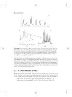
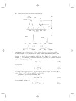
Figure 4.37 shows an example of the popular post-column derivatization of
amino acids with ninhydrin followed by UV detection at 405 nm. In this case
45 amino acids and related substances are separated on an ion exchange column
followed by reaction with ninhydrin at 130
◦
C in a 500-μL reactor (residence time
≈45 sec). Sample derivatization and reaction detectors have gradually lost popularity
as other HPLC detectors have been introduced and been made more effective.
REFERENCES
1. G. Hesse and H. Weil, eds., Michael Tswett’s First Paper on Chromatography,
M. Woelm, Eschwege, 1954.
2. V. G. Berezkin, ed., Chromatographic Adsorption Analysis: Selected Works of
M. S. Tswett, Ellis Horwood, New York, 1990.
3. A. Tiselius and D. Claesson, Arkiv. Kemi Mineral. Geol., 15B (18) (1942) 1.
4. A. J. P. Martin and S. S. Randall, Biochem. J., 49 (1951) 293.
5. C. G. Horv
´
ath and S. R. Lipsky, Nature, 211 (1966) 748.
6. J. J. Kirkland, Anal. Chem., 40 (1968) 391.
7. E. Haahti and T. Nikkari, Acta Chem. Scand., 17 (1963) 2565.
8. R. P. W. Scott and J. G. Lawrence, J. Chromatogr. Sci., 11 (1970) 65.
9. B. G. Julin, H. W. Vandenborn, and J. J. Kirkland, J. Chromatogr., 112 (1975) 443.
10. J. W. Dolan and J. N. Seiber, Anal. Chem., 49 (1977) 326.
11. L. R. Snyder and J. J. Kirkland, Introduction to Modern Liquid Chromatography,1st
ed., Wiley, New York, 1979, p. 136.
12. J. W. Dolan, LCGC, 14 (1996) 378.
13. L. R. Snyder and J. W. Dolan, High-Performance Gradient Elution, Wiley, New York,
2007.
14. J. J. Kirkland, W. W. Yau, H. J. Stoklosa, and C. H. Dilks, Jr., J. Chromatogr. Sci.,15
(1977) 303.
15. J. C. Sternberg, in Advances in Chromatography, Vol. 2, J. C. Giddings and R. A. Keller,
eds., Dekker, New York, 1966, p. 205.
16. D. Parriott, A Practical Guide to HPLC Detection, Academic Press, San Diego, 1993.
17. R. P. W. Scott, in Handbook of HPLC (Chromatographic Science Series, Vol. 78), E.
Katz, R. Eksteen, P. Schoenmakers, and N. Miller, eds., Dekker, New York, 1998, ch.
15.
18. D. T. Bach, US Patent 4,867,559 (Sept. 19, 1989).
19. M. H. Garrett, US Patent 6,542,231 (Apr. 1, 2003).
20. G. Cameron, P. E. Jackson, and M. V. Gorenstein, Chem. Aust., 60 (1993) 288.
21. A. G. Frenich, J. R. Torres-Laasio, K. De Braekeleer, D. L. Massart, J. L. Martinez-Vidal,
and M. M. Galera, J. Chromatogr. A, 855 (1999) 487.
22. Waters 996 Photodiode Detector: Peak Purity III: Interpretation of Peak Purity Plots
Appl. Note 970983, Waters, 1996.
23. F. K. Glowka and M. Karazniewicz-Lada, J. Chromatogr. B, 852 (2007) 669.
24. P. Vinas, N. Balsalobre, C. Lopez-Erroz, and M. Hernandez-Cordoba, J. Agr. Food
Chem., 52 (2004) 1789.
25. S. R. Bakalyar, M. P. T. Bradley, and R. Honganen, J. Chromatogr., 158 (1978) 277.
26. Y T. Wu, T R. Tsai, L C. Lin, and T H. Tsai, J. Chromatogr. B, 853 (2007) 281.
REFERENCES 197
27. I. N. Ackworth, Coulometric Electrode Array Detectors for HPLC (Progress in
HPLC-HPCE, Vol. 6), Brill Academic, Boston, 1997.
28. R. E. Parks and R. L. Marietta, US Patent 4018562 (1975).
29. Model 8060 Nitrogen Specific HPLC Detector, brochure A-8060-99-25M, Antek Instru-
ments, Houston, TX, 1999.
30. K. Petritis, C. Elfakir, and M. Dreux, LCGC Europe, 14 (2001) 389.
31. Jasco Incorporated, LCGC Applications Notebook (June 2003) 26.
32. L. Kott, W. B. Holzheuer, M. M. Wong, and G. K. Webster, J. Pharm. Biomed. Anal.,
43 (2007) 57.
33. F. Glowka, M. K. Lada, G. Grund, and J. Wachowiak, J. Chromatogr. B, 850 (2007)
569.
34. L. B. Allen, J. A. Koropchak, and B. Szostek, Anal. Chem., 67 (1995) 659.
35. Quant Technologies, QT-500 datasheet (2/ 2007).
36. D. Asa, Amer. Lab., 38(7) (2006) 16.
37. T. Gorecki, F. Lynen, R. Szucs, and P. Sandra, Anal. Chem., 78 (2006) 3186.
38. W. M. A. Niessen, Liquid Chromatography-Mass Spectrometry (Chromatographic
Science Series, Vol. 97), 3rd. ed., Taylor and Francis, London, 2006.
39. M. C. McMaster, LC-MS: A Practical User’s Guide, Wiley, Hoboken, NJ, 2005.
40. Current Practice in Liquid Chromatography-Mass Spectrometry,W.M.A.Niessenand
R. D. Voyksner, eds., Elsevier, Amsterdam, 1998.
41. I. D. Wilson and U. A. Th. Brinkman, J. Chromatogr. A., 1000 (2003) 325.
42. S. W. Huffman, K. Lukasiewicz, S. Geldart, S. Elliott, J. F. Sperry, and C. W. Brown,
Anal. Chem., 75 (2003) 4606.
43. G. W. Somsen, G. Gooijer, and U. A. Th. Brinkman, J. Chromatogr. A., 856 (1999)
213.
44. S. Down, Spectro. Europe, 16 (2004) 8.
45. K. Albert, J. Chromatogr. A , 856 (1999) 199.
46. A. J. Simpson, L H. Tseng, M. J. Simpson, M. Spraul, U. Braumann, W. L. Kingery, B.
P. Kelleher, and M. H. B. Hayes, Analyst, 129 (2004) 1216.
47. K. Blau and J. M. Halket, eds., Handbook of Derivatives for Chromatography, 2nd ed.,
Wiley, New York, 1993.
48. Application Manual: Amino Acids, Pickering Laboratories, Mountain View, CA, 2002.
49. Z. Xie, W. Shi, L. Liu, and Q. Deng, J. Chromatogr. B, 857 (2007) 53.
CHAPTER FIVE
THE COLUMN
5.1 INTRODUCTION, 200
5.2 COLUMN SUPPORTS, 200
5.2.1 Particle Characterization, 201
5.2.2 Silica Supports, 203
5.2.3 Porous Polymers, 212
5.2.4 Monoliths, 212
5.2.5 Other Inorganic Particles, 214
5.3 STATIONARY PHASES, 217
5.3.1 ‘‘Bonded’’ Stationary Phases, 218
5.3.2 Other Organic-Based Stationary Phases, 223
5.3.3 Column Functionality (Ligand Type), 225
5.4 COLUMN SELECTIVITY, 227
5.4.1 Basis of RPC Column Selectivity, 227
5.4.2 Column Reproducibility and ‘‘Equivalent’’ Columns, 235
5.4.3 Orthogonal Separation, 236
5.4.4 Other Applications of Column Selectivity, 237
5.5 COLUMN HARDWARE, 238
5.5.1 Column Fittings, 238
5.5.2 Column Configurations, 239
5.6 COLUMN-PACKING METHODS, 240
5.6.1 Dry-Packing, 240
5.6.2 Slurry-Packing of Rigid Particles, 240
5.6.3 Soft Gels, 244
5.7 COLUMN SPECIFICATIONS, 244
5.7.1 Manufacturing Standards, 244
5.7.2 Column Plate Number, 245
5.8 COLUMN HANDLING, 246
Introduction to Modern Liquid Chromatography, Third Edition, by Lloyd R. Snyder,
Joseph J. Kirkland, and John W. Dolan
Copyright © 2010 John Wiley & Sons, Inc.
199
200 THE COLUMN
5.1 INTRODUCTION
The column—the ‘‘heart’’ of the HPLC system—has changed greatly from the
beginning of HPLC in the mid-1960s. Columns have been improved for greater
separation speed and efficiency, as well as increased stability and reproducibility.
New stationary phases have been introduced for the extension of HPLC to a wider
range of sample types, or for better separations of compounds that have in the past
proved problematic. Today it is rare that a column cannot be found for solving
a particular HPLC separation problem. Early columns were made of glass, but
the need for higher pressure operation quickly led to the exclusive use of metal
columns. With the passage of time, columns became shorter and particles smaller
(Fig. 1.5g, h). Column lengths of 30 to 250 mm are commonly used today, with
particles that are 1.5 to 5 μm in diameter (larger particles are used for preparative
separations; see Chapter 15).
In this chapter we will examine the HPLC column, including the bare particle
or support, the added (‘‘bonded’’) stationary phase, and the column hardware.
Porous-silica particles in packed beds (as in Fig. 2.2) are most commonly used.
Particles can also be made from solids other than silica; the main value of non-
silica particles is their greater stability for use with extremes of temperature or
mobile-phase pH. Of special current interest are columns packed with very small
particles (<3 μm) for carrying out fast separations (Section 2.5.3.2).
Although very few workers will produce their own bonded-phase particles
(‘‘column packings’’), we will describe briefly how these materials are made; this
information can prove helpful in choosing a column or for troubleshooting. Column
characteristics that affect reversed-phase retention and selectivity (Section 5.4) can
also influence our selection of a column for a particular application. Column-packing
methods (Section 5.6) are described as further background for how ‘‘good’’ columns
are prepared. Column testing is covered in Section 5.7. Finally, column specifications
and column handling techniques are covered in Sections 5.7 and 5.8, as an aid for
good laboratory practice.
5.2 COLUMN SUPPORTS
Column packings consist of a rigid support plus an attached stationary phase (as
in Fig. 2.2b, which shows a silica particle with attached C
18
groups). In some
cases the support and stationary phase are the same; for example, an unbonded
silica particle is often used for normal-phase chromatography (Chapter 8). Silica
monoliths (Section 5.2.4) represent an alternative column support of more recent
vintage. Monoliths refer to columns composed of an interconnected, porous bed, as
opposed to columns packed with distinct particles (a monolith may be thought of as
one big particle that fills the entire column). In this section we will describe column
supports, their characterization, and how their properties affect their final use. Later,
we will discuss (1) how these supports can be modified to create column packings
for different purposes (Section 5.3) and (2) how the final particles are packed into
the column (Section 5.6).
5.2 COLUMN SUPPORTS 201
5.2.1 Particle Characterization
Particles can be characterized by their configuration or type, physical dimensions
(particle diameter), the nature and size of pores within the particle, and surface area.
The importance of particle diameter in influencing separation has been discussed (Fig.
1.5 and Section 2.4). Pore size and surface area are usually related reciprocally; as
pore diameter increases, the surface area decreases in roughly the same proportion.
The phase ratio Ψ (Section 2.3.1) is roughly proportional to surface area, and
retention is proportional to Ψ (Eq. 2.3); therefore retention increases as pore size
decreases and column surface area increases. The maximum weight of sample that
can be injected is also proportional to surface area (Section 2.6.2), so a greater
surface area is usually desirable—which suggests the use of the smallest possible
pore diameter (and smallest pores). However, solute molecules must be able to
enter the pores without hindrance, and this requires pores that are larger than the
solute molecule. For compounds with molecular weights <500 Da, the average
pore diameter should preferably be about 9 nm or larger. Larger molecules require
larger pores; for example, proteins are usually separated with 30-nm-pore particles
(Section 13.3.1.1). The interstitial volume of the column is the space between
particles; it is usually about 40% of the total column volume.
The physical characteristics of particles are important, and manufacturers
monitor these particle properties in various ways. The size of the particles is
especially important, as this largely determines the efficiency of the packed column.
While optical microscopy and air or liquid elutriation (or classification) methods
can provide this information, instruments for the measurement of particle size (e.g.,
the Coulter counter) are more convenient and quantitative; they can also provide
a particle-size distribution. A narrow particle-size distribution is preferred, as this
favors larger values of N (Section 5.2.2.1), and provides lower column pressure for
comparable efficiency.
Particle surface-area, average pore-diameter, and pore-diameter distribu-
tion typically are measured by the adsorption of nitrogen or argon, using the
Brunauer–Emmett–Teller (BET) procedure. Particles with average pore-diameters
>
30 nm (which are used less commonly) are preferably characterized by mercury
intrusion, which also can be used to measure pores as small as 3 nm. Mercury
intrusion does not work well for fragile particles (with a large pore volume) or for
soft polymer particles. Reference [1] should be consulted for additional information
on the measurement of the physical characteristics of HPLC particles.
5.2.1.1 Particle Type
As illustrated in Figure 5.1, several particle configurations are currently available for
HPLC. Totally porous silica particles (Fig. 5.1a) are the most common because of
their greater column capacity (allowing the injection of a larger sample weight) and
availability in a wider variety of options (stationary phase, particle and pore size,
column dimensions, etc.). The most popular particles have diameters in the 1.5- to
5-μm range. Today these particles are often prepared by the aggregation of much
smaller spheres (Section 5.2.2.3).
Pellicular particles (Fig. 5.1b) consist of solid, spheres that are covered with a
very thin surface layer of stationary phase. These silica- or polymer-based particles
(presently 1.5 to 2.5 μm in diameter, but much larger in the past) display larger
202 THE COLUMN
Porous-shell particle
Porous
shell
solid
core
throughpores
Perfusion particle
diffusive
pore
Micro-pellicular
particle
solid
core
(b)
(d)
(c)
Porous particle
(a)
Figure 5.1 Different particle configurations.
values of N for macromolecules, because of better stationary-phase mass-transfer
(smaller C-term, Section 2.4.1.1; [2, 3]). Because of their very low surface area, these
particles exhibit greatly reduced retention and are limited to much smaller weights
of injected sample (with a proportional decrease in detection sensitivity). Pellicular
particles are best suited for the analysis of major components (rather than trace
impurities), and have been used mainly for the separation of large biomolecules
(Chapter 13).
Superficially porous particles (also called fused-core™ particles, shell particles,
or controlled-surface-porosity particles) have a solid core with a porous outer shell
(Fig. 5.1c). These particles typically have diameters of 2 to 5 μm, with porous shells
of 0.25 to 0.5 μm in thickness. Superficially porous particles have much greater
surface areas than pellicular particles (∼3/4 as large as fully porous particles),
providing longer retention and allowing a larger weight of injected sample. The
thin, outer porous shell permits faster separations—especially for macromolecules
5.2 COLUMN SUPPORTS 203
[4, 5]. These particles also provide somewhat higher values of N than totally porous
particles (Section 5.2.2.1).
Perfusion particles (Fig. 5.1d) contain very large (e.g., 400- to 800-nm) pores
(through-pores), connected to a network of smaller (e.g., 30- to 100-nm) pores.
By comparison, most other particles have pore diameters of 8 to 30 nm (diffusive
pores). At high flow rates, solutes are carried into and out of perfusion particles by a
combination of diffusion and flow of mobile phase through the particle [6, 7]. This
additional contribution to stationary-phase mass transfer is claimed to reduce band
broadening, especially for large molecules at higher flow rates. Perfusion particles are
usually larger (e.g., 10 μm), permitting their use at lower pressures. These particles
are best suited for preparative-scale separations of macromolecules such as proteins;
they are little used for the analysis of small molecules.
5.2.1.2 Particle Size and Pore Diameter
From 1980 to 2000, particles with diameters of ∼5 μm were generally preferred
for routine separation. Particles of this size represent a good compromise in terms
of efficiency, pressure drop, convenience, equipment requirements, and column
lifetime. However, columns with particle diameters of 3 μm and smaller are
becoming more popular, mainly as a means for decreasing run time and increasing
sample throughput (Sections 2.5.3.2, 9.3.9.2). Because of the very narrow peaks
generated by small-particle columns, any extra-column peak broadening must be
minimized (Sections 2.4.1.1, 3.9), especially when smaller diameter columns are
used. Columns with particle diameters <2 μm are used mainly with equipment that
is capable of higher pressure operation (e.g., up to 15,000 psi; Section 3.5.4.3).
Table 5.1 summarizes some physical characteristics of HPLC particles and their
effect on separation from favorable (‘‘4’’) to unfavorable (‘‘1’’). Totally porous and
superficially porous particles with pore diameters of 8 to 12 nm are used most often
for the separation of molecules smaller than 10,000 Da. These column-packings
have surface areas of about 125 to 400 m
2
/g, which allow injected sample weights
of ≈50 μg (for column inner-diameters of 4–5 mm). Because peaks as small as a
few nanograms can be measured, both major and trace components can be assayed
in a single separation (or ‘‘run’’) with these columns.
Larger molecules (usually biomolecules such as proteins) require larger pores,
to avoid restricted diffusion within the pore, with a resulting decrease in column
efficiency (Section 13.3.1.1). Column packings with ≈30-nm pores typically are
used for separating molecules larger than 10,000 Da. If the pore diameter is at least
four times larger than the hydrodynamic diameter of the solute molecule, hindered
diffusion and lower values of N will be avoided [8]. Wider pores also mean smaller
surface areas and decreased sample weights. C
18
columns are used most often for
reversed-phase chromatography (RPC); the physical properties of some popular
columns of this type are shown in Table 5.2.
5.2.2 Silica Supports
Silica in the form of either particles or monoliths is the most commonly used
support for the production of HPLC packings. High mechanical strength is a strong
advantage for silica particles, allowing the formation of packed beds that are stable
for long periods and high operating pressures. Silica-based columns also provide
204 THE COLUMN
Table 5.1
Separation Characteristics of Particles for HPLC Columns
Particle Separation Pressure Ruggedness Operator Column
Type Speed Convenience Stability
a
5-μm totally porous 1 4 4 4 4
3.5 totally porous 2 3 4 4 4
2- to 3-μm totally porous 3 2 2 3 3
<2-μm totally porous 4 1 2 1 3
5-μm superficially porous 2 4 3 3 3
2- to 3-μm superficially porous 4 2 4 3 4
1.5-μm pellicular (nonporous) 4 1 2 1 1
Pore diameter
7- to 12-nm pores Small-molecule separations (<10, 000 Da)
(150–400 m
2
/g)
15- to 100-nm pores Large-molecule separations (
>
10, 000 Da)
(5–150 m
2
/g)
Note: Ratings in terms of advantage from moderate (1) to high (4).
a
Ability to tolerate high pressures or a rapid change in pressure.
Table 5.2
Properties of Some Commercial C
18
Particles
Packing Material Pore Diameter Surface Area Carbon Bonded-Phase
(nm) (m
2
/g) Load (%) Coverage (μmol/m
2
)
Ace C
18
10 300 15.5 na
c
Ascentis C
18
10 450 25 3.7
Halo C
18
a
9 150 8 3.5
Hypersil Gold C
18
17.5 220 10 na
Luna C
18
(2) 10 400 17.5 3.0
Sunfire C
18
10 340 16 na
TSK-GEL ODS-100V 10 450 15 na
XBridge C
18
b
13.5 185 na 3.1
Zorbax XDB-C
18
Plus 9.5 160 8 na
a
Superficially porous particles; other particles are totally porous.
b
Hybrid stationary phase (Section 5.3.2.2).
c
Data not available.
5.2 COLUMN SUPPORTS 205
higher values of N, compared to other support materials (Section 5.2.5). Spherical
particles can be synthesized with a wide choice of pore sizes (e.g., 10, 30, 100 nm),
particle sizes (e.g., 1.5, 2.7, 3.5, 5 μm), and in different particle configurations (as
in Fig. 5.1). Silica also can be used for monolithic columns (Section 5.2.4).
Another advantage of silica is that it can be bonded with different ligands (e.g.,
C
8,
C
18
, phenyl, and cyano; Section 5.3.1) for use with different samples and to
change separation selectivity. Silica-based columns are compatible with all organic
solvents and water, and do not swell or shrink with a change of solvent (as can be the
case for polymeric particles; Section 5.2.3); silica particles are especially suited for
gradient elution, where the mobile-phase composition changes during the separation.
Silica begins to dissolve in the mobile phase at pH
>
8 [9], which can result in a short
lifetime for columns packed with silica particles. However, special bonded-phases are
available that stabilize silica particles at higher pH (Section 5.3.2.1). Alternatively,
supports other than silica can be used for increased column stability at high pH
(Section 5.2.5). In the case of basic solutes, another limitation of silica has been a
tendency for tailing peaks. This problem has largely been resolved by the use of
higher purity silica (Section 5.2.2.2).
Most silica particles in use today are spherical in shape. Spherical particles
are more easily and reproducibly packed to yield efficient columns, and spherical
particles tend to be stronger. Large, irregular particles are used mainly for preparative
separations because of the lower cost of these materials and less need for high values
of N (Section 15.3.1.2). Silica-based particles are available that can withstand
pressures of 15,000 psi (especially superficially porous and pellicular particles,
because of their solid core). Spherical silica particles can be synthesized by several
different methods (Section 5.2.2.3 [1, 4]). Figure 5.2a shows the visual appearance
(surface topography, shape and size distribution) of some commercially available
silica particles, while a closer look at some popular (≈3-μm-diameter) particles is
shown in Figure 5.2b. Significant deviations from a true spherical shape can be seen
in some of these examples.
5.2.2.1 Column Efficiency
Particle size is a primary factor in determining column efficiency as measured by
the plate number N. This is illustrated in Figure 5.3 for several columns of varied
particle diameter; the plate height H (inversely proportional to N) is plotted versus
mobile-phase velocity u (proportional to flow rate). As the diameter d
p
of the porous
particles decreases from 5 to 1.8 μm, the plate height H decreases—corresponding to
an increase in column efficiency per mm of column length. For well-packed columns
of totally porous particles, the reduced plate height h = H/d
p
for a small molecule is
≈2, which until about 2006 was accepted as a lower limit for well-packed columns
filled with totally porous particles (Section 2.4.1).
The type of particle and its particle-size distribution can also affect column
efficiency, presumably by influencing the homogeneity of the packed bed. An
example is shown in Figure 5.3 for the 2.7-μm superficially porous column. This
column (with h ≈ 1.5) is more efficient than the column packed with 1.8-μm fully
porous particles. The superior efficiency of the 2.7-μm column may result from two
separate factors. First, the particle-size distribution of these particles is extremely
narrow (±5–6%, 1 SD), as shown in Figure 5.4. This can be compared with a