Introduction to Modern Liquid Chromatography, Third Edition part 89 pdf
Bạn đang xem bản rút gọn của tài liệu. Xem và tải ngay bản đầy đủ của tài liệu tại đây (166.53 KB, 10 trang )
836 TROUBLESHOOTING
17.4.3.5 Temperature Problems
Changes in column temperature affect values of t
R
and k.A1
◦
C increase in column
temperature will normally decrease retention by 1–2% (Section 2.3.2.2), so a method
that is operated without column-temperature control will be subject to changes in
retention as the temperature of the laboratory changes during the day. Temperature
changes also can influence selectivity (Section 6.3.2), so shifts in relative retention
may also be observed. Many laboratories have stable daytime temperatures, but for
energy conservation do not provide the same quality of temperature control at night.
Also, even though the laboratory temperature is relatively constant (as measured
at a wall-mounted thermostat), the local temperature can fluctuate significantly,
especially if a heating duct directs air at or near the HPLC system. For this reason
problems related to temperature tend to be exhibited as cyclic changes in retention
throughout the day. Temperature-related retention problems can be corrected by
using a column oven operated in a range where it has stable temperature control
(Section 3.7). Inadequate column temperature control also can cause peak shape
problems, as described in Section 17.4.5.3.
17.4.3.6 Retention-Problem Symptoms
This section discusses retention-time problems in terms of symptoms; see the related
items in Table 17.6.
Abrupt changes in retention are usually easy to isolate. If these occur when
the column is changed, the column itself is the most likely cause. Re-installation
of the previous column should confirm this. Column-to-column variation is much
less common with today’s high-purity, type-B silica columns, but was commonplace
with the lower-purity, type-A columns that may still be in use for some legacy
methods. Legacy methods may require adjustment of the mobile phase with each
new column in order to meet system suitability; an alternative is to order several
columns from the same batch of packing material. Redevelopment of the method
for a more robust separation is another solution, but it may not be economically
feasible. Substitution of an equivalent column (Sections 5.4.2, 6.3.6.1) that is more
reproducible is another option. Also, don’t overlook the possibility that the wrong
column was inadvertently installed.
If the change in retention occurred when a new mobile phase was formulated,
the simplest solution is to make another batch of the mobile phase. Be sure that the
correct mobile-phase pH is used (Section 7.2.1), and that the pH is adjusted prior to
the addition of organic solvent.
Abrupt changes in retention are fairly common when a gradient method is
transferred from one HPLC system to another. This usually is due to differences in
the system dwell-volume between different equipment (Section 9.2.2.4). Sometimes
these differences can be compensated by a change in mobile-phase conditions, the
injection timing, or modification of the system plumbing (Section 9.3.8.2; also
Section 5.2.1 of [18]).
If retention changes abruptly when none of the above conditions exist, and
there is no obvious change in the system operating conditions, it is likely that there
is an equipment problem (e.g., check-valve failure), a leak (Table 17.3), a bubble
(Table 17.4), or a column-temperature problem (Section 17.4.3.5).
17.4 COMMON SYMPTOMS OF HPLC PROBLEMS 837
Drifting retention times are a symptom of some instability in the system. When
a method is set up, it is not uncommon for retention times to drift for the first few
injections; this may be even more pronounced when a new column is installed. The
most likely cause of retention-time drift for RPC is incomplete equilibration of the
mobile phase and column. Incomplete equilibration can be especially pronounced
for ion-pair separations, where 20 to 50 column volumes may be required for
equilibration (Section 7.4). For most isocratic methods, however, retention times
should stabilize after the first two or three injections. For gradient elution, an increase
of the equilibration time between runs may be required to stabilize retention times,
especially if the first few peaks in the run are eluted close to t
0
(Section 9.3.7).
A less-common cause of retention-time drift is the presence of slowly equili-
brating active sites on the column that become saturated after several injections.
When this is the case, several ‘‘priming’’ injections to deactivate the column (Sections
3.10.2.2, 13.3.1.4) may solve the problem. Make several large-mass injections of the
sample in a row (it usually is not necessary to make a complete run for each injection,
just inject several times with perhaps a 30-second delay between injections), then
allow the normal method cycle to run. Sometimes priming injections are required
just once for a column, whereas other samples may require priming injections each
time the method is started.
If retention time drifts in a continuous fashion over an entire sample batch,
it suggests that something is continuously changing in the method; for example,
the mobile phase may be unstable. The use of a volatile buffer (e.g., ammonium
carbonate) coupled with helium sparging can result in evaporation of the buffer with
a change in mobile-phase pH. Similarly loss of the organic component of the mobile
phase can occur, but this is uncommon during the course of a day. Re-formulation
of the mobile phase on a daily basis may be necessary for some methods. If helium
sparging is used (Section 3.3.2), note that it takes only one volume of helium to
degas an equal volume of mobile phase (e.g., 1-L of He for 1-L of mobile phase), so
a few minutes of vigorous sparging is all that is needed. If continuous sparging is
necessary for pump or detector stability, turn down the helium supply to a trickle
rather than allow vigorous sparging to continue. If the presence of a small amount
of dissolved air is not a problem, in-line vacuum degassing (Section 3.3.3) usually
is more convenient and is adequately effective in most cases—without causing
mobile-phase evaporation.
Variable retention times for some or all peaks between chromatograms are
symptoms that some variable is not adequately controlled. In one example where
retention-time variation was observed only in the middle of gradient runs, the
cause was related to a mobile-phase proportioning problem (see Section 5.5.4.1 of
[18]). An intermittent check-valve failure will cause intermittent flow-rate, and thus
retention changes. Temperature fluctuations in the laboratory can change retention
on a run-to-run basis. Usually the causes and fixes for variable retention times are
similar to those for drifting retention.
When retention times have decreased, several possible causes exist. If
retention-time loss correlates with larger injected sample-mass and right-triangle
peak shapes (e.g., Fig. 17.15a), mass overload of the column is likely. Reduction of
the injected sample weight should correct this problem. See the discussion of tailing
and distorted peaks in Section 17.4.5.3 for more information on mass overload.
838 TROUBLESHOOTING
When all peaks in the chromatogram show reduced retention, the problem
is associated with the column, mobile-phase, temperature, or flow rate. Consult
Table 17.5 and the appropriate discussion in Sections 17.4.3.1 through 17.4.3.5 for
more information.
When only some peaks in the run have shorter-than-normal retention times,
an unexpected change in the system chemistry is suggested; for example, a change in
ionization of acidic or basic solutes. Check the mobile-phase pH (prior to addition
of organic). Usually a change in the %B will affect all peaks in the run (though not
necessarily in an identical way); if this is suspected, make a new batch of mobile
phase. Note also that the accuracy of on-line mixing of the mobile phase can vary
among different HPLC systems. An aging column can also affect the retention of
just some peaks in the chromatogram; installation of a new column will serve to
identify the column as the problem source.
Inadequate retention of polar samples is sometimes a problem during RPC
method development. If the sample is ionic, it may be possible to change the
mobile-phase pH so that the sample is converted to its non-ionized form, which will
be less polar and better retained (Section 7.3). An alternative is to use ion pairing to
improve the retention of ionic samples (Section 7.4). If the sample is neutral, use of
a more polar mobile phase (less strong solvent) should increase retention. However,
if the %-organic is ≤5%, column de-wetting may occur for alkyl-silica columns
(Section 5.4.4.2), with resultant loss of retention. Use of a column containing
embedded polar groups or ‘‘AQ’’ type columns may be useful. If other attempts
to retain polar compounds by RPC are not successful, a change to normal phase
(Chapter 8) and especially hydrophilic interaction chromatography (HILIC, Section
8.6) may provide the desired results. See the additional discussion regarding poor
retention of polar solutes in Section 6.6.1.
Retention times that are too long usually have similar causes as those that
are too short. Refer to Table 17.5, Sections 17.4.3.1 through 17.4.3.5, and the
discussion of smaller than expected retention.
17.4.4 Peak Area
With today’s data systems, quantification by peak area is much more common than
by peak height (Section 11.2.3), so we will assume peak-area measurements for
the current discussion; however, the same troubleshooting process can be used for
either peak-height or area problems. If a change in retention accompanies a peak-area
problem, first correct the retention problem before addressing the peak-size problem.
Peak-area response for most methods will be very consistent over time. For
example, repetitive injections of the same, well-retained sample (e.g., k
>
2) with UV
detection and a signal-to-noise ratio of S/N
>
100, peak area should vary <1%
between runs (Section 3.10.1.3). However, smaller peaks, shorter retention times,
and/or the use of some other detectors may generate less reproducible results. The
following discussion of peak-area related problems is organized by (1) peaks that are
larger than expected (Section 17.4.4.1), including peaks in blanks and carryover, (2)
smaller than expected peaks (Section 17.4.4.2), and (3) peak areas that are variable
from run to run (Section 17.4.4.3). A summary of symptoms and solutions is listed
in Table 17.7. In this section, we will assume that the method had been working
properly for previous sample batches.
17.4 COMMON SYMPTOMS OF HPLC PROBLEMS 839
17.4.4.1 Peak Area Too Large
For peak areas that are too large, the first step is to determine if the problem
is reproducible, and if it is related to just one sample or solute, or all samples.
Answers to these questions usually will require re-injecting one or more samples
and/or examining several chromatograms from a batch of samples. If the area is
not reproducible between several injections of the same sample, see Section 17.4.4.3
(variable areas). If the sizes of all peaks vary in the same proportion, check to be
sure that the correct injection volume is selected. Another possible cause is faulty
sample preparation—check to be sure that the dilution or concentration steps were
done properly. If the areas for different peaks in the chromatogram have changed
by different proportions, the detector settings may be at fault. Check the detector
wavelength (UV detector, Section 4.4), interface adjustments (evaporative detectors,
Sections 4.12–4.14), time constant, and so forth.
Peaks that appear in a blank injection generally come from one of two sources:
late elution or carryover. A peak that is not fully eluted in one run can appear in the
next (or later) run; if the sample contains other components, the extra peak will be
much broader than the neighboring peaks. This is illustrated in Figure 17.5, where in
a a broad peak X (arrow) appears at approximately 2 minutes in the chromatogram.
In Figure 17.5b, the run of Figure 17.5a is extended, showing peak X both in the
previous run (at ≈2 min) and at its normal place in the chromatogram (≈7min).If
peak X must be quantified in the run, the run can be extended as in Figure 17.5b to
include the peak in the correct run. If the peak is not of interest, several options are
available. The run can be extended as in Figure 17.5b, the run time can be adjusted
so that the peak appears in the following chromatogram in a region where no other
peaks are present, a step-gradient can be used to flush the peak from the column,
or sample cleanup can be modified to remove the peak from the sample prior to
injection. Carryover results when a small portion of the sample is trapped in or
adsorbed on the surfaces of the autosampler and shows up when a blank is injected.
Check for carryover as described in Section 17.2.5.10.
(a)
(b)
X
10024
Time (min)
68
X X
Figure 17.5 Example of late elution. (a) Broad peak (X) appears out of place in chro-
matogram; (b) entire chromatogram; extended run time allows peak to elute in proper position
in chromatogram (≈7min).
840 TROUBLESHOOTING
17.4.4.2 Peak Area Too Small
Peak areas that are smaller than expected can have the same root cause as peak
areas that are too large, and the process discussed above (Section 17.4.4.1) can be
followed to isolate and identify problems due to small peaks. Of course, carryover
and late-elution problems are less applicable for peaks that are too small. Other less
common causes of small peaks are a detector time constant that is too large (Section
4.2.3.1), a data sampling rate that is too slow (Section 11.2.1.1), peaks that are off
scale (underintegrated), or peaks that are improperly integrated (Section 11.2.1.4).
17.4.4.3 Peak Area Too Variable
If the precision of a method is worse than it has been historically, this will appear
as peak areas (or heights) that are more variable than expected. If there also is a
retention-time problem, it is best to correct it first (Section 17.4.3). There are many
possible causes of variability in peak areas, some of which are also discussed in
Section 11.2.4. Nearly any step in sample preparation and analysis can contribute
to peak-area variation. Some of the more likely sources are discussed below.
The first step is to determine if the results from a single sample are consistent.
If replicate injections of the same sample give consistent peak areas, all the processes
from sample injection onward are working properly. The source of the problem
then has to be something prior to placing the sample in its vial. Possible problems
of this kind include sampling, equipment, and sample preparation errors. Sampling
is the process of selecting a representative (in this case, equivalent) sample (Section
16.3)—if the master sample is not homogeneous, subsamples may not be equivalent.
If volumetric or gravimetric laboratory equipment is not accurate or operating
properly, error can be introduced, a common source of such error is a pneumatic
pipette that is worn beyond acceptable tolerances. The typical sample-preparation
process (Chapter 16) has multiple steps in each of which small errors are possible
that can affect analyte recovery (e.g., filtration, evaporation, dilution). In a stepwise
manner modify the sample preparation process or circumvent specific steps to isolate
the source of the problem.
If replicate injections of the same sample give inconsistent peak areas, the
problem is likely due to the processes that take place from sample injection onward.
The most likely sources are the autosampler, pump, detector, or data-processing
steps. First check the autosampler by rerunning the reproducibility test of Section
3.10.1 to see how it compares to past tests (Section 17.2.4); make any necessary
repairs. Pump malfunction can lead to a change in mobile-phase flow rate, another
possible source of peak-area variation (check this by running a flow-rate test,
Section 3.10.1.3). Detection problems, such as detector overload or poor wavelength
selection might affect one peak and not another. If detector overload is suspected
(very large peaks, e.g.,
>
1 AU for a UV detector), dilute the sample or inject a
smaller volume to see if smaller peaks give more consistent areas. For LC-MS
detectors with an electrospray interface (Section 4.14.1.1), a poorly performing
spray tip can result in different amounts of sample getting into the MS at different
times in the chromatogram. The integration and data workup process might have
problems, such as if a peak had a start or stop time improperly set, or the data
sampling rate was too slow (Section 11.2.1). Another occasional case of variable
peak area can occur if a frozen sample is not properly thawed and/or mixed prior
17.4 COMMON SYMPTOMS OF HPLC PROBLEMS 841
to injection. A gradient of analyte concentrations may then occur from the top to
the bottom of a vial. In this case replicate injections from such a sample may show
a descending or ascending (depending on the nature of analyte and matrix) series of
peak areas.
17.4.5 Other Problems Associated with the Chromatogram
In addition to the symptoms discussed in the preceding sections, chromatograms
often exhibit obvious defects in appearance which can be used to isolate the cause
of the problem. This section covers three of these:
• baseline drift
• baseline noise
• peak shape
17.4.5.1 Baseline Drift Problems
Baseline drift is defined as a continuous rise and/or fall of the chromatographic
baseline extending over a period of tens of minutes to hours (Section 4.2.3.1). Drift
can occur in a rising, falling, or cycling pattern, as well as exhibit other characteristics.
Some of the symptoms and causes of drift are summarized in Table 17.8. It should
be noted that some drift is expected;, for example, one UV detector specifies drift
of ≤2 × 10
−4
AU/hr at 250 nm at constant room temperature and with air in the
cell and ≤3 × 10
−4
AU/hr with a room temperature fluctuation of ≤2
◦
C [19].
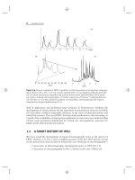
Periodic drift is characterized by a cyclic pattern, with the baseline rising and
then falling (or vice versa) over one or more runs. This is most common with gradient
elution within a single run, as a result of a mismatch of the detector response to the
mobile phase A- and B-solvents. This is illustrated in the baselines of Figure 17.6
[20]. Baseline (Fig.17.6a) is for a gradient run from 5–80% water/MeOH at 215 nm,
with drift of ≈0.9 AU (because MeOH has much stronger absorbance than water
at this wavelength; see data of Table I.2, Appendix I). Such drift is normal and
02 46810
0.0
0.1
(b,c)
1.0
(a)
time (min)
absorbance (AU)
(b) 215 nm
(H
2
PO
4
–
added to A-solvent)
(c) 254 nm
(a) 215 nm
Figure 17.6 Baselines obtained using water-methanol or phosphate-methanol gradients,
5–80% B in 10 minutes. (a) Gradient at 215 nm and 1.0 AU full-scale; solvent A: water; sol-
vent B: methanol; (b)sameas(a), except solvent A: 10 mM potassium phosphate (pH-2.8) and
0.1 AU full-scale; (c)sameas(a), except 254 nm and 0.1 AU full-scale. Adapted from [20].
842 TROUBLESHOOTING
is a problem only if it precludes accurate integration of the chromatogram. If the
drift is unacceptable, there are three general approaches for addressing the problem.
One option is to add a UV-absorbing reagent to the A-solvent. In the example of
Figure 17.6b, the use of 10-mM phosphate buffer (pH-2.8) instead of water reduced
the drift of Figure 17.6a by nearly 30-fold. Because drift will be less severe at longer
wavelengths, another option is to increase the detection wavelength, provided that
the sample response is acceptable at the new wavelength (UV detection is assumed;
other detectors may offer other options). The effect of a wavelength change is seen
by comparing Figure 17.6a (215 nm) with Figure 17.6c (254 nm). Alternatively,
a less-absorbing organic solvent might be chosen. In this case ACN could be used
instead of MeOH (not shown); ACN has negligible drift at 215 nm and may be used
successfully for gradients at 200 nm or above. Of course, a change in mobile-phase
A or B can change the chromatographic selectivity, so further adjustments in the
method may be necessary (only applicable for method development).
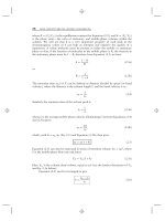
Negative baseline drift can be a greater problem because data systems typically
stop integrating when the detector reads less than −0.1AU(−10% drift). Thus,
if the gradient-elution baseline of Figure 17.7a [20] is encountered, it is likely that
the baseline will drop off scale in a negative direction, with loss of the data (it
was possible to collect this baseline only by turning off the auto-zero function and
manually setting the baseline start at +1 AU). As in Figure 17.6a, c, the drift of
Figure 17.7 is much less at 254 nm (Fig. 17.6c) than 215 nm (Fig. 17.6a). The
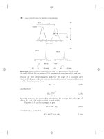
negative drift of Figure 17.7a could be converted into a (more acceptable) positive
drift by adding a UV-absorbing buffer to the B-solvent (Fig. 17.8a [20]). Another
possible fix with some data systems is to adjust the scale of the data channel to a
range of 0.0 to −1.0AU.
In some cases, however, the use of mobile-phase additives as in Figure 17.8a
cannot correct severe, negative drift. In the example of Figure 17.9a, the baseline
for this ammonium bicarbonate-methanol gradient exhibits a negative dip in the
010203040
−0.5
−1.0
0.0
time
(
min
)
absorbance (AU)
(a) 215 nm
(b) 254 nm
Figure 17.7 Baselines obtained using ammonium acetate-methanol gradients. Solvent A:
25-mM ammonium acetate (pH-4); solvent B: 80% methanol in water; gradient: 5–100%
B in 40 minutes. (a)215-nm detection; (b)254 nm. Adapted from [20].
17.4 COMMON SYMPTOMS OF HPLC PROBLEMS 843
400
0.2
0.1
0.0
−0.1
10 20
time (min)
(b) 254 nm
(a) 215 nm
absorbance (AU)
30
Figure 17.8 Baselines obtained using equimolar ammonium acetate-methanol gradients as in
Figure 17.8, but with buffer added to B-solvent. Solvent A: 25-mM ammonium acetate (pH-4)
in 5% methanol; solvent B: 25-mM ammonium acetate in 80% methanol; gradient 0–100% B
in 40 minutes. (a) 215-nm detection; (b)254 nm. Adapted from [20].
02 46 810
−0.2
0.0
−0.1
0.1
time (min)
absorbance (AU)
(a) 215 nm
(b) 254 nm
Figure 17.9 Baselines obtained using ammonium bicarbonate-methanol gradients. Solvent
A: 50-mM ammonium bicarbonate (pH-9); solvent B: methanol; gradient: 5–60% B in 10
minutes (a) 215-nm detection; (b)254 nm. Adapted from [20].
middle at 215 nm. Adjustment of the absorbance of either the A- or B-solvent
cannot solve this problem. Although this mobile phase is unacceptable for detection
at 215 nm (Fig. 17.9a), detection at 254 nm (Fig. 17.9b) poses no problem. An
alternative detector might also be used; for example, bicarbonate mobile phases
are commonly used with LC-MS, without creating baseline problems. Fluorescence
detection is another option used to obtain flat baselines for gradient elution of
fluorescent analytes.
844 TROUBLESHOOTING
A change in temperature of the column (and mobile phase) is another major
cause of periodic baseline drift. A change in mobile-phase temperature changes
the refractive index of the mobile phase and the transmission of light through
the UV-detector cell. If the column is operated without adequate temperature
control (Section 3.7.1), the baseline is likely to drift as the laboratory temperature
changes. Temperature-related baseline drift can be confirmed by related changes
in retention times with temperature. See Section 17.4.3.5 for further discussion of
temperature-related problems.
Other types of isocratic baseline drift are not cyclic, and these may arise from
different causes. Slow system equilibration after a change of conditions (mobile
phase, column, column temperature, flow rate, etc.) will result in initial baseline
drift that usually subsides within 30 to 60 minutes. Baseline drift associated with
equilibration may be accompanied by retention-time drift. Similarly, when a detector
is first turned on, the detector response may drift for a few minutes or even hours as
the lamp, electrodes, or other detector elements warm up and stabilize.
17.4.5.2 Baseline Noise Problems
Disturbances in the baseline are referred to as baseline noise. The characteristics
of baseline noise can help identify its source. Baseline disturbances can be periodic
or random, and the duration of the disturbances can be shorter (short–term noise)
or longer (long-term noise) than the width of a chromatographic peak. Moreover,
baseline noise is superimposed upon any baseline drift. In addition to the discussion
below, consult Table 17.9 as well as Sections 3.3.1 (degassing), 3.8.3 (data rates),
4.2.3 (noise), 11.2.1.1 (data sampling contributions), 11.2.4.2 (chromatographic
sources), and 11.2.4.3 (detection sources).
High-frequency short-term noise shows up as the ‘‘buzz’’ on the baseline (e.g.,
Fig. 4.5) resulting from electronic noise on the electrical circuits. This has a period
of 60 Hz (North America) or 50 Hz (most of the rest of the world), depending
on the frequency of the alternating-current electrical supply. High-frequency noise
usually can be significantly reduced as discussed in Section 4.2.3.1 by the use of
a cleaner electrical supply (e.g., use an uninterruptable power supply, UPS) and/or
selection of a larger detector time-constant. Figure 4.5 shows the reduction of noise
by approximately 300-fold by the use of a simple noise filter.
Random and low-frequency short-term noise can result from several different
sources. Insufficient degassing can lead to the introduction of air bubbles into
the HPLC system. Bubbles trapped in the pump head(s) can also cause baseline
disturbances as the pressure fluctuates from one piston stroke to the next, giving a
regular pattern to the baseline noise. Bubbles in the pump should be accompanied by
pressure fluctuations as described in Section 17.4.2.3. Bubbles that make it through
the pump, or that are formed after the pump by mixing inadequately degassed
mobile phase in high-pressure-mixing systems, often will be kept in solution due to
the system pressure. However, when the dissolved air leaves the column, the pressure
is greatly reduced and the bubbles may reform. As the bubbles pass through the
detector, random, sharp spikes may appear, especially with optical detectors (e.g.,
UV-visible, Section 4.4; fluorescence, Section 4.5; refractive index, Section 4.11).
Detectors that evaporate the mobile phase (e.g., Sections 4.12–4.14) are, of course,
not susceptible to mobile-phase bubble problems. If the bubble is trapped in the flow
17.4 COMMON SYMPTOMS OF HPLC PROBLEMS 845
cell, a large shift in baseline may result. Adding a back-pressure restrictor after the
detector (Section 4.2.1) may solve bubble problems in optical detectors.
Electrical spikes are similar to bubbles. But to distinguish their presence from
bubbles, turn off the pump flow and monitor the baseline. If the spiking continues,
the problem is electronic; if the spiking stops and the baseline remains steady, the
problem is due to a bubble. The use of better degassing procedures (Section 3.3.1)
is the first line of defense against bubbles. A back-pressure restrictor (Section 4.2.1)
will keep bubbles in solution until after they leave the detector.
The selection of a data collection rate that is too fast can result in excessive
short-term baseline noise. As described in Section 3.8.3, the data rate should be set to
collect ≈20 points across the peak. Higher data rates will increase the baseline noise
while having little benefit on the amount of signal collected, so the signal-to-noise
ratio (Section 4.2.3) will worsen. Lower data rates may reduce baseline noise, but
this risks reducing the signal as well, so the signal-to-noise ratio may suffer.
Long-term noise shows up as baseline disturbances that are comparable in size
(or wider) to normal peaks. One common source of long-term noise is the presence
of late-eluted materials in the sample (see the discussion of Fig. 17.5 in Section
17.4.4.1). As retention time increases for solutes or background interferences in
the sample, the band width increases and the peak height decreases. Late-eluting
peaks from prior separations can accumulate over time, resulting in a drifting and
erratic baseline. A strong-solvent flush of the column (e.g., 25 mL of methanol
or acetonitrile) often will remove strongly retained material from the column. For
this reason a strong-solvent flush is recommended following each batch of samples
(isocratic separation assumed). For some methods a column flush may be needed
more often. Gradient methods usually are less susceptible to late-eluted interferences
because they have a strong-solvent column-wash built into every run. Heroic efforts
to remove strongly retained materials (e.g., flushing with acid, base, chaotropes,
or methylene chloride) can be effective but can also damage the column. A better
approach is to use improved sample pretreatment (Chapter 16) to reduce the sample
burden of late-eluted materials. Remember, the column is a consumable item. Once
500 or so samples are analyzed, the cost per sample for the column becomes a trivial
portion of the overall analysis cost, so column replacement often is a better choice
than extensive column cleaning or sample pre-treatment.
Sometimes long-term noise shows up as regular baseline fluctuations, as in
Figure 17.10 (note that the y-axis is 1 mAU full scale). Usually cyclic baseline
disturbances are caused by pump problems and will be accompanied by pressure
0.001 AU
01020304050607080
Time (min)
Figure 17.10 Cyclic baseline noise that was attributed to interference from an electronic air
filter in the laboratory. Adapted from [21].