CorelDRAW X5 The Official Guide part 22 pps
Bạn đang xem bản rút gọn của tài liệu. Xem và tải ngay bản đầy đủ của tài liệu tại đây (329.1 KB, 10 trang )
The upper limit for nudge distance is 600 inches, which is fair enough, because, for
example, nudging a shape 600 inches to move it is more easily accomplished by simply
entering the intended position in the property bar’s X and Y fields (then you press
ENTER to
apply the move).
Nudge distance can be set on-the-fly within the workspace, and Super and Micro
Nudge scale apply to the new nudge distance. With nothing selected, set a new value
in the Nudge Distance box.
Ill 7-3
There’s an easy way to remember some modifier keys. In many applications, CTRL
means “constrain,” “to limit”—while SHIFT often means “to add to” or “to
extend.” So super-nudging can be thought of as an extension to normal nudge
distances (you hold
SHIFT while pressing arrow keys), and micro-nudging is a
constrained version of normal nudging (you hold
CTRL).
Specifying Units, Origin, and Tick Divisions for Your Rulers
In the fields below Nudge options, you’ll find all the controls for what appears, and where,
on the rulers displayed on your drawing page. Here’s how each option controls ruler
appearance:
●
Units Units are measurement values. Choose a Horizontal unit measure to specify
unit measures for all drawing units in your document. To specify different units of
measure for vertical ruler and drawing units, click to deselect the Same Units For
Horizontal And Vertical Rulers option, shown in Figure 7-4.
●
Origin Although you can manually set the origin as described in the previous
section, you can also perform precise origin definition using this field. The origin
point can be set anywhere from –50 to 50 yards, in precise increments as small as
0.001 inch.
●
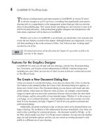
Tick Divisions Tick divisions are the evenly spaced numeric labels seen bracketing
the smaller increments displayed by your ruler—for example, if you are using inches
as the unit, the tick divisions are 1, 2, 3, and so on. Tick divisions are automatically
set according to the unit of measure selected. For example, standard measure displays
a default of eight divisions per tick, and metric measure displays ten divisions. Desktop
publishing and printing units such as didots, picas, points, and ciceros display using
174 CorelDRAW X5 The Official Guide
six divisions per tick. The option to Show Fractions is also available and set by
default while a unit measure is selected. The top of Figure 7-5 shows two divisions
per tick; below it is the standard eight subdivisions; and at bottom, with the Show
Fractions check box unchecked in the Rulers area of Options, decimals are now
shown for ticks.
To set the Spacing and Frequency of your ruler, see “Setting Grid Properties” later
in this chapter.
Editing Drawing Scales
Scale drawing is used when the dimensions involved in drawing actual sizes are either too
large or too small to be practical. For example, a world atlas at 1-to-1 (1:1) scale would be
hard to carry around, and almost as hard to print. You can set up a drawing scale by first
setting the units; click the Units drop-down on the property bar. Then click the Edit Scale
button in the Rulers page of the Options dialog (
CTRL+J is the shortcut). In the Drawing
Scale dialog, you can quickly apply a scale ratio, or set your own custom scale. By setting
CHAPTER 7: Measuring and Drawing Helpers 175
7
FIGURE 7-5 Choose tick divisions and whether fractions or decimals display on rulers.
2 tick divisions
8 tick divisions
Decimal labels for divisions instead of fractions
1 foot to equal a mile (5,280 feet), it’s then simple to draw accurate maps and directions
around town.
Ill 7-4
The Typical Scales drop-down list includes a selection of the most commonly used
drawing ratios ranging from 100:1 to 1:100, with the most common standard measure scales
included. When selecting ratios, the first number represents the object Page Distance; the
second number represents the real-world distance, labeled “World Distance.” Usually small
objects such as circuitry and clock parts are illustrated using ratios where the Page Distance
is larger than the World Distance. Conversely, the best setup for a technical drawing of a
skyscraper is to set Page Distance much smaller than World Distance.
The moment you change either the Page Distance or the World Distance, the Typical
Scales selection in the drop-down list turns to Custom. Page Distance is the measured
distance on your document page, while World Distance refers to the distance represented by
your ruler and drawing units in your document. Settings can be made independently of each
other and to different units of measure to a range between 1,000,000 and 0.00001 inches in
increments of 0.1 inch.
Calibrating Ruler Display
You buy a Lamborghini Gallardo (about $200,000); you pull into a gas station, and you want
to put Regular in the tank? No. Similarly, you can’t expect precision when you use CorelDRAW
on an uncalibrated monitor. CorelDRAW provides a very simple way to ensure what you see
on your monitor screen matches real-world measurements. Occasionally, your display might
176 CorelDRAW X5 The Official Guide
not show perfectly square pixels, and as a result, your 5-inch line in a very important
drawing might measure 4.88" when you print it. To calibrate the rulers in CorelDRAW to
match your screen, to match real-world output, you’ll need a plastic foot-long ruler (clear is
better than solid, about $1 at a stationery store), about 30 seconds, and the following steps:
1. In a new document create a 5"-wide square. With the Rectangle tool, hold CTRL
(constrains proportions to 1:1), and then drag while watching the size fields on the
property bar. If you’re close but not precisely 5", type 5.0 into either field with the
Lock Proportions icon clicked (see following illustration), and then press
ENTER.
Ill 7-5
2. Using the Zoom tool property bar options, set your view magnification to 100 percent.
3. Using your physical $1 ruler, measure the object you created on your screen. If both
CorelDRAW’s rulers and your physical ruler agree it’s a 5" square, your ruler display
is accurate. If the measurements don’t match, CorelDRAW’s toolbox Options dialog
has the fix.
4. Open the Options dialog (CTRL+J).
5. Click to expand the tree directory under Workspace | Toolbox, and then click Zoom |
Hand Tools. This displays the Zoom, Hand options on the right of the dialog. First,
click to select the Zoom Relative To 1:1 option.
6. Click Calibrate Rulers to display the ruler calibration reference rulers and Resolution
options, shown in Figure 7-6. Notice the vertical and horizontal ruler bars that intersect
at the center of your screen. This represents your current ruler drawing units.
CHAPTER 7: Measuring and Drawing Helpers 177
7
7. Using your ruler, measure both the vertical and horizontal rulers on your screen to
see that they match. If they don’t match, increase or decrease the Horizontal and/or
Vertical options using the spin boxes until the onscreen rulers match your $1 ruler.
See Figure 7-6.
8. Click OK to close the calibration dialog, and then click OK again to close the
Options dialog. Your rulers are now calibrated.
Introducing the Indispensable CorelDRAW Grids
A page grid is a customizable, by default nonprinting, overlay that extends beyond the
printable page onto the pasteboard area at all viewing resolutions and viewing qualities.
It’s not only an excellent visual reference for scaling and aligning objects vertically and
178 CorelDRAW X5 The Official Guide
FIGURE 7-6 Clicking Calibrate Rulers displays reference rulers and Resolution options.
horizontally, but it also can be used in combination with CorelDRAW’s Snap To Grid
option. To make the grid visible, right-click with the Pick tool over an empty area of the
page, and then choose View | Grid from the pop-up menu. To modify the Grid, right-click
over either ruler or the ruler origin, and then choose Grid Setup.
Ill 7-6
Setting Grid Properties
You’re going to have a variety of designing needs, which will certainly call for different
appearances of grids, which is why they’re customizable. Changing grid-line frequency and
spacing is often needed. You can use options in the Grid page of the Options dialog to tailor
your grid just the way you need it to appear. To open this page, as shown next, choose View |
CHAPTER 7: Measuring and Drawing Helpers 179
7
Show grid
Grid Setup (right-click)
Setup | Grid And Ruler Setup from the command menus, or right-click your ruler and
choose Grid Setup.
Ill 7-7
Use the Object Manager to set all grid properties, including visible, printable, and/
or editable states. Grids are controlled by the Grid layer properties, which is a
layer on the master page. To open the Object Manager, choose Window
Dockers
Object Manager (see Chapter 9).
The Grid page’s Grid Lines Per Inch and Inches Apart options for units might look
similar, but there’s an important distinction. The Grid Lines Per Inch (“frequency”) option
gives you control over the grid appearance according to the number of lines that appear
within a given distance. The Inches Apart (called “spacing” in CorelDRAW version X4)
option controls the physical space between the grid lines based on distance. Both are set
according to the current drawing units choice, and you choose frequency or spacing;
choosing both would be impossible. You can also set the horizontal and vertical spacing
independently of one another, which is very useful when you have an object such as a tall
fluted glass that you want to put etching on. You’d use more horizontal than vertical grid
lines, and your design would turn out flawlessly.
180 CorelDRAW X5 The Official Guide
When illustrating or drawing based on a specific unit of measure—such as inches—
formatting your grid to match the ruler unit of measure is a smart thing to do. For
example, if rulers are set to display inches using a Tick Division of 8 per inch,
setting the grid to a Grid Lines Per Inch value of 8 vertical and 8 horizontal lines
per inch causes grid lines to appear every eighth of an inch while using a Drawing
Scale ratio of 1:1 (actual size).
Display Grid as Lines or Dots
Also on the Grid page of the Options dialog, you control how your grid appears—either as
lines or as dots. By default, new documents are set to the Show Grid As Lines option. However,
a design, for example, of a checkerboard might make the grid fairly invisible and as a
consequence useless; you’d opt for the display of Show Grid As Dots. Conversely, you’re
going to lose a solar system or two if dots are chosen for grids when you’re drawing an
astronomy chart (use lines)!
Using Snap-To Commands
The Snapping feature helps you move a shape to an exact location when it’s close to grid
lines, guidelines, and other objects. Think of snapping as magnetism: you hold a paper clip,
for example, close enough to a magnet, and eventually it snaps to the magnet. In CorelDRAW
you use the Pick tool and Shape tool to get snapping. The Snap To drop-down menu on the
property bar is your ticket to defining what snaps to what on your drawing page.
Snapping is one quick route to precise manual aligning and distribution of table callouts,
symmetrical patterns, and just about any design that requires some regularity to placed shapes.
And if you don’t need it, it’s easy to turn off.
●
Snap To Grid To have your drawing shapes snap and align to the document grid,
click the drop-down on the property bar, or press the shortcut
CTRL+Y to toggle the
feature on and off. When objects snap to a grid, they snap to the grid lines, and
you’ll feel an even stronger attraction when you move an object close to grid
intersection points.
Ill 7-8
CHAPTER 7: Measuring and Drawing Helpers 181
7
●
Snap To Guidelines Guidelines are covered later in this chapter. To cause your
objects to snap to any type of guideline, choose this option from the drop-down list.
●
Snap To Objects To have objects snap to and align with other objects, choose
Snap To Objects from the drop-down list; it’s faster to remember the shortcut
ALT+Z.
When objects are set to snap to each other, they can use snap points on either the
source (the magnet) or target (the object that’s attracted) object. Snap points are set
using options and modes in the Snap To Objects page of the Options dialog (see the
later section, “Setting Snap Behavior”).
●
Snap To Page When you want to draw an object that’s aligned perfectly to any
edge of the drawing page, use this Snap To option. Snap To Page is also great for
snapping an existing object’s edge or corner to the edge of the page.
●
Dynamic Guides This feature in CorelDRAW X5 is akin to object snapping. Press
ALT+SHIFT+D, or use the drop-down menu to toggle the dynamic guides on or off.
This feature is covered in detail in the next section.
Snapping To It
1. You have a web page to design, with six 1-inch squares (three across, two down),
with a ½-inch space between them. Don’t get out a pocket calculator, and don’t
resort to colorful language—at their defaults, Snap To Grid and Snap To Objects
make this task go like a charm. Enable Snap To Grid and Snap To Objects from the
Snap To drop-down list and make sure Grids are turned on.
2. With the Rectangle tool, begin close to a grid intersection, and then drag down and
to the right until the property bar tells you either the height or width of the rectangle
is very close to 1". Release the mouse button when your cursor is over a grid intersection.
3. Choose the Pick tool.
4. Drag the rectangle over to the right until you see one vertical grid separating it from
the original square, but don’t release the mouse button yet. One space is on each side
of this line, and together they represent half an inch.
5. Right-click while the left mouse button is still depressed, and then release both
buttons to drop a copy. What you’ve done is duplicate the original square to a new
position. This is an important, quick technique for duplicating shapes.
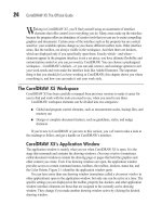
6. Repeat steps 4 and 5 to build the array of evenly spaced squares, as shown in Figure 7-7.
Notice that when an object’s edge is on, or even close to, the grid when Snap To is
turned on, you’ll see a tiny blue label indicating the snap-to point. You’re not limited
to shape edges as the origin of a snapping point; setting behavior for snapping origins
is covered later in this chapter.
182 CorelDRAW X5 The Official Guide
Snapping behavior isn’t limited to the grid. In fact, you don’t even have to have the
grid turned on to snap objects to one another; press
ALT+Z and then all your
objects are sticky.
Setting Snap Behavior
On the Snap To Objects page of the Options dialog, you can control snapping behavior in
precise detail when moving and drawing lines or objects. You choose Tools | Options
(
CTRL+J), click to expand the tree directory under Workspace, and then click Snap To
Objects.
The Snapping Radius feature requires that you have a shape and a different object (or
guideline or grid intersection) to which it snaps. Proximity to the “magnetic” snapping
object is important—you can’t have an object snap to a different object that is miles away.
However, in the Snap To Objects page, you have control over the strength of the magnetism,
by setting the Snapping Radius pixel distance.
To customize snapping behavior to suit the type of drawing you’re building, you enable
or disable the following features on the Options page:
●
Snap To Objects On Clicking this check box toggles the Snap To Objects feature
on or off. You can also do this from the Snap To drop-down list on the property bar.
●
Snapping Radius Use this to set snapping sensitivity, based on screen proximity
to snap points. Experiment with what works best for you in a specific design situation;
CHAPTER 7: Measuring and Drawing Helpers 183
7
FIGURE 7-7 Duplicating and aligning objects makes accurate composition of a design a breeze.