CorelDRAW X5 The Official Guide part 35 ppsx
Bạn đang xem bản rút gọn của tài liệu. Xem và tải ngay bản đầy đủ của tài liệu tại đây (431.85 KB, 10 trang )
fill and is ordered on top of the target objects. Just click a foreground color on the
color strip, and the new object will become immediately apparent.
You can use shaping operations on bitmaps. See Chapter 24 on how to create
in
valuable cropping effects on your photos using shaping operations and other
techniques.
Using the Shaping Docker
Under the Arrange menu, you’ll find all the shaping commands. Also, the Shaping command is
on this menu, which opens the Shaping docker in the workspace. As with all dockers, you can
detach (undock) this palette so it floats near your work (demanding fewer “mouse miles”), and
this docker offers more options than when you use the shaping operations from the property bar.
Because of their operation, Simplify, Front Minus Back, and Back Minus Front only have an
Apply button, and Create Boundary has Place Behind Selected and Leave Original check boxes.
The first three shaping commands in the selector are applied in slightly different ways
from the others. To Weld, Trim, or Intersect, you must have at least one object selected and
another unselected (but still in view) for the commands to be available. Once Weld, Trim, or
Intersect is selected, the docker will display available options, shown here. Clicking the
docker command button begins the action.
304 CorelDRAW X5 The Official Guide
After: new object is moved
Before Create Boundary
Shaping command selector
Preview window
Object options
Command button
The preview window on the docker doesn’t actually change; it’s an illustration that
shows the result of using each operation. The Object options check boxes are what you use
to set what object, if any, remains after an operation. Leave Original is equivalent to “make a
copy so I don’t lose my originals,” and the options are as follows:
●
Source Object(s) When this option is selected, the object you selected before the
shaping operation remains after the command has been applied.
●
Target Object(s) With this option selected, the object you Trim, Weld to, or
Intersect with remains after the command has been applied.
Let’s give this docker a spin. First, create two shapes; the Rectangle tool is fine to make
shapes you won’t need later, so they’re expendable in this example:
1. If you haven’t already done so, create the objects on which you want to base your
new shape, and position them in such a way that the shape created by their
overlapping portions represents your new shape.
2. Select one of these overlapping objects, and open the Shaping docker by choosing
Window | Dockers | Shaping.
3. Choose Weld, Trim, or Intersect from the selector at the top of the docker.
4. Choose which original object(s) you want to remain after the command has been applied
by clicking Source Object(s) and/or Target Object(s), and then click the command button
at the bottom of the docker to apply the command. Notice your cursor has changed to
one of three targeting cursors, depending on your shaping operation.
5. Click the object you want your selected object to Trim, Weld to, or Intersect with.
Your new shape is immediately created based on the overlapping area of your
existing objects.
The outline and fill properties of newly shaped objects are determined by the
properties of the target object.
Choosing Simplify, Front Minus Back, or Back Minus Front requires that at least two
objects are selected. If only one object is selected, you’ll get an attention box politely telling
you so and asking if you’d like to try again. With any of these commands, the shaping is
applied when you click the Apply button in the Shaping docker.
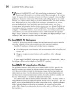
Working Examples of Object Shaping
If you’ve seen some stunning CorelDRAW creations and said to yourself, “Wow, that
must’ve taken that artist ages to do all that work,” nope, it probably didn’t: the artist put
object shaping to work. The following shows just three of thousands of creative possibilities
for shaping operations; these are just a few examples to kindle your efforts.
CHAPTER 11: Editing Objects 305
11
Here is an example problem and a solution using the Trim operation. The chicken came
first, then the need to make the chicken drawing look as though it’s peeking through the
broken eggshell. The chicken drawing is composed of several grouped sub-objects; the Trim
operation trims all objects in a group. Walk through the next set of steps to see how the Trim
operation solves a lot of the manual effort of editing dozens of objects to visually integrate
the chicken drawing into the scene. All the shapes needed to perform the Trim operation
have been added for you; just focus on how to use the Trim operation.
Trimming a Chicken
1. Open Chicken.cdr. The goal is to place the toy chicken drawing so that it looks as
though it’s peeking out of the half-shell at right.
2. With the Pick tool, drag the chicken group’s objects, and position them so the lower
half of the chicken is over the eggshell.
3. Choose Arrange | Shaping | Shaping to display the Shaping docker.
4. Select the dashed outline shape. If you were designing this composition from
scratch, the Pen tool would be ideal for drawing such a shape. The blue dashed
outline is only to call attention to the object in this example—the shape can be any
outline color or style.
5. Choose Trim from the drop-down list. Put a check in the Target Object(s) check box
so a copy of the whole chicken remains in the drawing. Why spoil a perfectly good
drawing?
6. Because only one object is selected, you now click Trim on the Shaping docker, and
the docker queries you on what you want trimmed.
306 CorelDRAW X5 The Official Guide
7. With the special cursor, click over the chicken.
8. With the Pick tool, move the lower (whole) chicken out of the way to see the results.
Try a click-drag over the wing.
Figure 11-1 shows a combination Weld and then a Trim, although Back Minus Front
would work as the second step, too. The problem in this composition is that a specific font
is needed in stencil style, but the artist doesn’t have such a typeface. So Arial is first used,
and then:
1. Draw several rectangles over areas that need to be removed from the text to create
the stencil effect.
2. Create duplicates of one narrow rectangle by using the drop-a-copy technique: drag
a rectangle to a new location, and then tap both mouse buttons before releasing both
buttons. Doing this keeps consistency between areas to be removed from the text.
3. After all the rectangles are in position, marquee-select the rectangles, and then use
the Weld command to make a single object out of the rectangles.
4. Remove the single shape from the text by using it as the Source object in the Trim
operation. The text is trimmed.
5. Finally, use Effects | Add Perspective to make the text appear as though it’s on the
3D crate. The text probably could use some rotation, but you get the idea.
CHAPTER 11: Editing Objects 307
11
Target object
retained and
moved
With the outline selected, click
Trim, and then click the chick.
Figure 11-2 uses Back Minus Front, Weld, and an Arrow shape (covered in Chapter 16)
to create a complex-looking design for a corporate logo. First, a circle is drawn using the
Ellipse tool in combination with holding
CTRL (to constrain ovals to perfect circles). Then,
to put a smaller circle centered inside the first, you hold
SHIFT, drag the original circle’s
corner-bounding box handle toward the center, then right-click before releasing the left
mouse button to create a scaled duplicate. Back Minus Front is chosen on the Shaping
docker with both objects selected; click Apply and you have a perfect doughnut object. The
Arrow shapes come in all four directions on the property bar; four arrows are dragged to
create with this tool, they’re arranged, and then all four arrows are selected. The Weld
operation is chosen on the Shaping docker. Then with the large arrow cursor, the doughnut is
clicked to indicate it’s the target object. This could be the end of the story, but in only a few
clicks, the resulting shape can be extruded and rotated. See Chapter 19 for the complete
details on object extrusion—3D is yours to experiment with within CorelDRAW.
308 CorelDRAW X5 The Official Guide
FIGURE 11-1 Weld and then Trim are used to make a stencil treatment out of the text.
Black rectangles are welded.
Welded rectangles trim text.
Effects | Add
Perspective plus
transparency
Fillet/Scallop/Chamfer
The Fillet/Scallop/Chamfer docker can be displayed by choosing it from Window | Dockers,
and with it, you have your choice of truncating sharp corners of an object you draw. This
docker will not alter a curved path segment: a shape that consists of straight paths is the best
to use with this feature; objects with a combination of curved and straight segments will
only be affected along the convergence of two straight path segments.
When Fillet/Scallop/Chamfer evaluates sharp direction changes along a path, it “rounds
off” the point of a convex area toward the inside of the path and increases concave areas.
This is a terrific feature for quickly building elegant objects such as furniture pieces,
machine parts, and nice ornaments for desktop publishing documents. When you enter a
positive value in the Radius field (or use the elevator buttons on the docker), you see a faint
outline preview in your document, and then you click Apply when you’re happy with the
preview. Fillet/Scallop/Chamfer is a destructive operation, unlike the shaping operations, so
if you want to keep your original object, duplicate it before using this docker.
●
Fillet Rounds the corners of an object
●
Scallop Trims a semicircle from the corner of an object
●
Chamfer Lops a straight angle off a corner at an angle perpendicular to the
interior angle of the corner
CHAPTER 11: Editing Objects 309
11
FIGURE 11-2 Complex illustrations don’t need to take a lot of time. Get to know the Shape
tools, and what you envision is only a few clicks away.
Back (larger circle)
Minus Front
Weld arrow
shapes to
doughnut object.
Extrude with bevel edge.
Figure 11-3 shows the effects of the Fillet/Scallop/Chamfer docker on the same zigzag
object created with a single-click and the Pen tool. Because the Radius of this trimming
effect is measured in page units, it’s usually a good idea to keep rulers visible in your
document, and to refer to them to achieve the exact degree of corner truncation you need.
310 CorelDRAW X5 The Official Guide
FIGURE 11-3 Use the Fillet/Scallop/Chamfer docker to take the corners off an object with
intricacy and classic style.
Use the page rulers.
PowerClips
CorelDRAW PowerClips change the appearance of a shape by hiding certain areas of its exterior
with a different shape. This, unlike other reshaping operations, is completely nondestructive, and
the clipping object can release the inner clipped object(s) at any time. Consider the usefulness
of PowerClips: You can hide most of an object from view and put other objects behind the
PowerClip. You can play a dozen possible scenarios for the composition you have on a page, and
never commit to any of them, unlike with trimming an object.
To give you an idea of the creative power of PowerClips, follow these steps with a
document whose objects have already been created for you. The assignment is to put a
design on the bottom of a flower vase, stencil-style, so parts of the vase’s original color still
show through in different regions. It’s not hard work when you’re familiar with PowerClips.
PowerClipping a Design onto an Object
1. Open Flower and Vase.cdr. To the left you’ll see a grouped pattern with transparency.
Below it is the same pattern with an envelope applied to make the pattern look bulged, as
it would when viewed on the surface of a round shape such as the vase drawing here. At
right, over the vase, is a thin yellow outline shape that is a fairly accurate trace over the
vase. This will be your PowerClip shape for the pattern—it will hide all shapes outside of
it. If you’d like to use the Envelope tool to experiment with the non-enveloped grouped
pattern, Chapter 20 provides the complete documentation on this feature.
CHAPTER 11: Editing Objects 311
11
Pattern with transparency
Clipping object
Pattern with transparency and an envelope
2. Select the bottom pattern with the Pick tool, and then drag it over so it’s on top of
the yellow outline object, making certain that all parts of the pattern overlap the
outline. You don’t want gaps in the pattern as it’s displayed on the vase.
3. Choose Effects | PowerClip | Place Inside Container.
4. A huge arrow becomes your cursor. Click the cursor over the yellow outline, and the
pattern scoots inside the container object.
5. The container object is now selected. Right-click over the No Fill color well on the
Color Palette to remove the outline, or alternatively, choose None for the Outline
Width from the drop-down list on the property bar. See Figure 11-4.
Although the preceding example shows how to mask the exterior of a group of shapes,
a PowerClip container can also have an outline width, color, and a fill. In any case, the
nondestructive property of PowerClips will serve you in a number of design situations.
312 CorelDRAW X5 The Official Guide
FIGURE 11-4 Let empty areas in patterns and other complex drawings show through a
PowerClip object.
Occasionally, an object “inside” the PowerClip container might not be aligned perfectly
relative to your overall composition. You also might like to do a little editing to the contained
object(s). This is not directly done on the page. Here are the editing options for a PowerClipped
object:
●
To reveal the object for editing or repositioning relative to the PowerClip object,
right-click over the object, and then choose Edit Contents from the pop-up menu. A
blue outline indicates the size and position of the PowerClip container. When you’re
done editing, right-click and then choose Finish Editing This Level.
●
To undo the PowerClip effect, you can press CTRL+Z right after making the command,
or right-click over the PowerClip object, and then choose Extract Contents. Your
PowerClipped object(s) and the container are restored to their original condition, but
not always to their original position on the page.
●
To quickly reposition the contents of a PowerClip container, right-click and then
choose Lock Contents To PowerClip. This is a toggle on and off state: when it’s
unlocked, you can reposition the container by dragging with the Pick tool. You can
also scale and rotate the container without affecting the contents. When it’s locked,
the contents travel with the container objects wherever you drag.
The Knife Tool
The Knife tool functions like a knife you’d use in the real world—except you can run with it
and it requires no sharpening— and feels quite natural to use. You begin by hovering over an
object area where you want to begin the cut, your cursor changes its appearance to signify it
is ready, and then you click-drag to the end of the cut, the other side of the object. The result
is two separate closed objects. As with many of CorelDRAW’s tools,
SHIFT and CTRL can be
used as modifier keys as you work with the knife, and in the case of the Knife tool, these
modifier keys add precision to your cuts. You’ll find the Knife tool in the toolbox grouped
together with the Crop, Eraser, and Virtual Segment Delete tools.
CHAPTER 11: Editing Objects 313
11
Knife tool