CorelDRAW X5 The Official Guide part 66 pdf
Bạn đang xem bản rút gọn của tài liệu. Xem và tải ngay bản đầy đủ của tài liệu tại đây (547.53 KB, 10 trang )
Ill 20-19
●
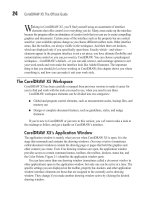
Local Using the Local distortion option has the effect of varying the Amplitude
value of your distortion effect around the center origin. At the center of the distortion
effect, Amplitude is at its maximum value. Amplitude then tapers to 0 as the distortion
emanates from the center origin of the effect. The results of applying the Local
distortion option while the Frequency is varied are shown here:
Ill 20-20
To clear a distortion effect, click Clear Distortion Effect in the property bar or
choose Effects | Clear Distortion. If you’ve applied successive distortions, each
distortion is cleared individually in order, from the last distortion applied to the
first, so you can step out of the effect incrementally.
614 CorelDRAW X5 The Official Guide
Frequency = 21
Frequency = 48
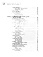
To bring all this Zipper talk down to a practical level, the following illustration shows
two creative, commercial uses. At left, the Zipper distortion is used as a coupon border. The
only finessing needed was to apply a dashed Outline pen style. At right, the diagram of a
sewing pattern is gussied up a little by making the cut marks look as though real pinking
shears were used.
Ill 20-21
Twister Distortion
Twister distorts the outline paths and nodes of objects by rotating the outer areas around the
center (which is largely undistorted), either clockwise or counterclockwise, to achieve an
effect much like a child’s pinwheel toy. Twister options on the property bar include rotation
direction, rotation amount, and degree of additional rotation.
Ill 20-22
CHAPTER 20: Envelope and Distortion Effects 615
20
Twister Mode
Counterclockwise
Rotation
Clockwise
Rotation
Additional
Degrees
Complete
Rotations
(This used to be
a rectangle.)
Controlling a Twister distortion is simple; rotation can be clockwise or counterclockwise,
but increasing the rotation really dramatizes the effect of this mode. Whole rotations can be set
to a maximum of 9; additional rotations can be added up to 359°—nearly another full rotation.
Figure 20-12 shows some of the widely differing effects that can result—it all depends on the
number of rotations and the object used as the target for the effect.
Objects applied with a distortion effect can’t be edited using the Shape tool unless
the effect is cleared. However, you can convert a distorted shape to curves
(
CTRL+Q), and then edit to get the object you need.
Getting Hands-On with the Distortion Tool Markers
The best way to shape a distortion is interactively, by dragging directly on the Distortion
tool markers with your cursor. Depending on which distortion mode you’re using, these
interactive markers serve different purposes.
Which interactive markers are available depends on which mode (Push And Pull, Zipper,
Twister) you’ve chosen, but basically you have a Start handle shaped like a diamond, which
sets the center of the distort effect. The Start handle is connected to the End handle, which is
used to define the direction of the effect and also the amplitude (with the Push And Pull and
616 CorelDRAW X5 The Official Guide
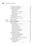
FIGURE 20-12 Using simple objects and the Twister mode of the distort effect, you can create
wild, organic shapes.
Original rectangle
180° clockwise
270° clockwise
Original ellipse
35° clockwise Two complete clockwise
rotations + 240°
Zipper modes). Generally, interactive markers involve a center marker and at least one other,
each joined by a directional guide. When Zipper distortion is being applied, a small extra
slider appears between these two markers and controls the amount of frequency applied. In
the case of Twister distortions, the outer marker serves as a handle for determining the
degree angle and amount of rotation you apply to an object.
To realign the center marker (the Start handle) with the center of the distortion,
click the Center Distortion button in the property bar while the Distortion tool and
the distorted objects are selected. It’s the button with the + symbol, to the left of the
Convert To Curves button.
Changing Push and Pull Interactively
Push and pull distortions are controlled using two markers: a diamond shape indicates
the center of the distortion, and a square marker controls amplitude. The center marker
can be moved around the object, but the amplitude marker movement is constrained to
left or right movement. Dragging the amplitude marker left of center changes the negative
amplitude values, causing the push effect. Dragging it right of the center marker changes
the positive values, causing the pull effect. Figure 20-13 shows the effects of different
marker positions.
CHAPTER 20: Envelope and Distortion Effects 617
20
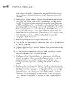
FIGURE 20-13 Push and pull distortions are controlled by a diamond shape and a square
marker onscreen.
Original object
Pull effect
Center marker
Amplitude marker
Push effect Offset pull Offset push
Working with the Zipper Control Handles
Using Zipper distortion, the movable diamond marker represents the center origin, and the
square marker to the right controls the amplitude value. Use the small rectangular slider on
the dashed blue centerline to set frequency by moving it left or right. Dragging it right
increases the frequency, adding more zigzag shapes to your object’s path, while dragging it
left does the opposite. You also have the opportunity with Zipper mode, unlike the fixed
positions of the markers in Push And Pull mode, to move the amplitude handle to slant the
zigs and zags in a direction.
Ill 20-23
Exactly as with envelopes, the distortion effects can be copied using the toolbox
Attributes eyedropper tool.
Changing Twister Interactively
Controlling Twister distortions by dragging with your cursor over the markers is the most
productive (and fun) way to apply this distortion mode; one click-drag lets you set two
properties at once, both of which have a dramatic effect on the distortion. The markers
during a Twister distortion are a diamond-shaped center marker and a round-shaped rotation
handle. Dragging the rotation handle around the center marker causes distortion based on
the angle of the guide between the center and rotation markers and the number of times the
rotation marker is dragged completely around the center marker. You’ll also see a dashed
blue line connecting the markers, which provides a quick visual reference of the beginning
618 CorelDRAW X5 The Official Guide
Original object
Lower frequency
Center marker
Frequency slider
Amplitude marker
Higher frequency
Center offset
Center offset
and Amplitude
marker rotated
angle of the Twister distortion and the current angle of distortion you define. Figure 20-14
shows examples of Twister distortions and positions of the markers.
To copy a distortion to a new object, select an object, click the Copy Distortion
Properties button in the property bar, and use the cursor to target an existing
distortion.
Using Distortion Presets
The property bar Preset list for distortion effects gives you the power to apply, save, and
delete saved distortions, as shown here:
Ill 20-24
CHAPTER 20: Envelope and Distortion Effects 619
20
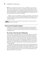
FIGURE 20-14 It’s best to use the control handles to create Twister distortions.
Original
object
One complete
rotation
Center marker
Rotation handle
One complete rotation
using center offset
Partial rotation
Partial rotation, using
center offset
Preset list
Click to delete selected preset from list.
Click to add distortion as preset.
Exploring Distortion Presets
When the Distort tool is the current tool selected, choosing a preset from the list
immediately applies a new distortion effect to a selected object. If you’ve created a really
awesome distortion effect and you want to save the effect while the distorted shape in your
document is selected, you can add it as a new distortion preset by clicking the Add Preset
button. The Delete Preset button permanently removes a selected distortion preset from the
list; therefore, think twice about ever clicking this button. To delete a preset, nothing must be
selected on the page; then the minus button becomes active. Only user presets can be
deleted, not CorelDRAW shipped-with presets.
Between distortion and envelope effects covered in this chapter, you should be well on
your way to massaging an object or object group from something close to what you like to
exactly what you like and need. Remember, these are dynamic effects, so you don’t
permanently change that shape you’ve worked for hours on. And if you need to exchange
data with a client or coworker who doesn’t own CorelDRAW:
●
Take pity on them.
●
Convert a copy of your effects work to curves (CTRL+Q), and then export the distorted
or enveloped object to any number of file formats CorelDRAW supports. Effects are
proprietary to CorelDRAW, but vector information can be used in other vector design
programs and modeling programs or exported as typefaces—you name it.
Blends and contours are the topic of the next chapter, each with their own use, and you
can actually take what you know now about distortions and apply a contour to a distorted
object. Will it look weird? Yep, and interesting. Just think of it as adding to weirdness, and
building on your knowledge!
620 CorelDRAW X5 The Official Guide
CHAPTER 21
Blends and Contours
621
A
lthough they’re different effects, blends and contours share the common trait of
creating many shapes based on control shapes; the additional shapes are dynamically
linked to the control object, and the “in-between” objects will vary in size, color, and outline
shape depending on how you set up the effect. Blends and contours are a boon to the designer
who wants to add shading to flat color fills in a way that fountain fills do not. Additionally,
blend objects can be used to illustrate the transition between two objects of similar or completely
dissimilar shape. This chapter takes you through the use of blends and contours so you can
add these effects to your bag of illustration tricks and create outstanding, intriguing work.
Blend and Contour Effects: Similarities with Distinctions
The blend effects create a series of objects between objects in a number of steps you
define—an object can be a closed path, a group of objects, and even a line (an open path).
The properties of each step are influenced by the objects used in the blend. The contour
effect also creates additional objects in steps; however, only one object is used to produce a
contour. When you imagine a contour effect, think of an object surrounded by the same
shape radiating outward (or inward) in a concentric pattern, like the waves produced when
you drop a pebble in a still pond. Depending on the assignment, you’ll choose the contour or
blend to achieve the exact look you need. The following sections explain the properties of
the effects you can manipulate, and then you can decide which effect to reach for when you
need a complex graphic or a smooth, shaded fill in an illustration area.
Blending as Illustration Shading
If you’ve ever tried to add depth to a drawing and found that you’re not up to speed with the
Mesh fill tool and that a fountain fill doesn’t do the trick, the solution is to blend a large shape
through transition objects to a smaller object inside the large one. By making, for example, the
outer shape darker than the inner one, you can position a highlight wherever you need it on
the face of a drawing of a hardware tool or a fork or a drinking glass . . . you get the picture.
Similarly, a contour can be used to create a highlight; however, the contour object should be
symmetrical, such as an ellipse, to achieve the highlight effect. You’ll often see blend effects
used in illustration work for creating photorealistic illustrations, but regardless of whether the
visual content of a drawing is real-life accurate or a whimsical cartoon, with blends you add
depth and suggest lighting and the type of material on an object. The left side of Figure 21-1
shows a decent drawing of a frankfurter in perspective, but you and other viewers detect that
there’s something missing from the illustration. At right, you can see a Wireframe view of the
same drawing, except several blends and contours have been added on a new layer in
CorelDRAW. You’ll see how to do this stuff later in this chapter.
In Figure 21-2 you can see the finished illustration in Enhanced view in CorelDRAW’s
drawing window. About eight pairs of objects were used, different sizes and different colors,
and what you see here is smooth shading and highlights that suggest lighting and a little
622 CorelDRAW X5 The Official Guide
CHAPTER 21: Blends and Contours 623
21
FIGURE 21-1 A drawing, especially a perspective drawing of an object, can appear flat until
you add shading with blends and contours.
Uniform fills
Blends
Contours
Extruded text
FIGURE 21-2 The main difference between this illustration and that in Figure 21-1 is depiction
in Figure 21-1 and illustration here. Illustrations are complete visual ideas, from
outline shape to interior fills.