CorelDRAW X5 The Official Guide part 67 pptx
Bạn đang xem bản rút gọn của tài liệu. Xem và tải ngay bản đầy đủ của tài liệu tại đây (646.58 KB, 10 trang )
shininess on the frankfurter, thus creating a visual impression of strength, size, and other
qualities that help the audience read very quickly, “Oh, that’s a frankfurter! It looks really
large and bright! It probably has a lot of calories and nitrites, and the bun doesn’t look like
whole wheat…” Seriously, the more complexity you build into an object’s fill, the more you
tell your visual story, and the more readily the audience will pick up on that story and fill in
more details. And before you know it, you’ve sustained your audience’s attention.
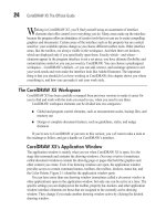
Blends can also be used to create a lot of similar objects very quickly; the trick is to
blend between similar objects that are quite a distance apart on the page. Figure 21-3 shows
an example of two groups of objects blended to create a bar graph; the reference lines were
blended from two identical lines. This is a graph with an even, upward progression. However,
when you need to create similar blend objects that don’t follow an even progression, you
use the Break Apart (
CTRL+K) command to break the relationship between the blend control
objects, then ungroup the blend group, and finally, you edit the individual blend objects to
create a more random transition from object to object.
624 CorelDRAW X5 The Official Guide
Photorealism Is Achieved Through Complex Fills
Many world-class designers—particularly in the field of 3D animations—have made
the observation that the shape—the silhouette—of an object is usually not as visually
interesting as the texture on the surface of that object. This is one of the reasons for
using CorelDRAW blends and contours to make drawings not only more visually
interesting, but also more photorealistic in appearance. For example, just about anyone
can draw rectangles that represent a box viewed in perspective; in fact, this task takes
about 1 minute using the Extrude tool. However, your audience probably won’t
immediately see the drawing as a box until it has shading; the side facing a hypothetical
light source would be lighter than the side(s) facing away from the light. Additionally,
some text or a simple drawing placed in the correct perspective on one face of the box
drawing would also help convey an image of a box. Graphics inside of graphics add
visual complexity to illustrations. They are the “fills” for objects, and the more
complex you make an illustration, the more closely the drawing suggests a real object:
the world is a visually complex place.
The more attention you pay to fills for objects, the more quickly and successfully
you’ll communicate a visual idea to an audience. With the speed of today’s
communications, you need to make your point—a selling point or just a point about
fine art—fast and thoroughly before someone loses interest and moves on to a different
web page!
The Blend Tool and Property Bar
The tool to use for the blend effect is the Blend tool; it’s in the toolbox, grouped with other
effects tools, shown here.
Ill 21-1
CHAPTER 21: Blends and Contours 625
21
FIGURE 21-3 Objects in this chart were created using blends.
Blend tool
When the Blend tool is chosen, the property bar offers options (shown in Figure 21-4)
for customizing the effect. By default, 20 intermediate steps are created between two blend
control objects.
Creating a Simple Blend Effect
You might want to work with similar objects to create blends that look like repeats—
rubberstamped copies of the original objects—but there’s another creative use for the Blend
tool. You can morph totally dissimilar objects, and the resulting blend will probably contain
a lot of interesting and useful transitional shapes. Work through the following tutorial to
experiment with a basic blend effect between a star and an ellipse object.
A Basic Blend Between Very Different Shapes
1. Choose the Star tool; it’s in the group on the toolbox with the Polygon tool. Click-
drag a star that’s about 1" in size at the top left of the drawing page. Fill it with
yellow on the Color Palette, and give it a 4-point blue outline. First, choose 4 pts.
from the Outline width drop-down box on the property bar, and then right-click any
blue color well on the Color Palette.
2. Choose the Ellipse tool (F7) and then click-drag an ellipse at the top right of the
page. Fill it with blue and give it a yellow outline, but keep the outline width at the
default of 0.5 pt.
3. Choose the Blend tool from the toolbox. Your cursor changes and the property bar’s
options are all dimmed because a blend doesn’t exist yet on the page.
626 CorelDRAW X5 The Official Guide
FIGURE 21-4 When the Blend tool is used, the property bar has options to customize your
blend effects.
Blend Preset
Options
Blend
Steps
Blend
Spacing
Number of
Blend Steps
Blend
Direction
Loop
Blend
Clockwise
Blend
Acceleration
Options
More Blend
Options
Path
Properties
Clear
Blend
Blend Offset Spacing
Direct
Blend
Counterclockwise
Blend
Size
Acceleration
Starting And
Ending Objects
Copy Blend Properties
4. Click inside the star and then drag until your cursor is inside the ellipse. Once you
release the mouse button, a series of new objects appears, and the property bar
comes to life with almost all options available.
5. Twenty steps is too many for this example: type 2 in the Blend Steps field on the
property bar, and then press
ENTER. As you can see in the following illustration, the
blend shapes make an interesting progression; the outline color makes the transition
from blue to yellow; the fill color transitions from yellow to blue; and the intermediate
shapes are some interesting stars in stages of distortion as they become the ellipse.
These intermediate star-like objects are actually a little difficult to make using the
standard drawing tools!
Ill 21-2
To remove a blend effect, click the blend portion of the effect to select it, and choose
Effects | Clear Blend; or, while using the Blend tool, click to select the blend effect
portion, and click the Clear Blend button in the property bar.
Looking at the Components of a Blend
The blend effect you built in the previous tutorial creates a fun composition, but to build
on your knowledge—to be able to create more complex blends—it’s a good idea to now
examine what really went on, and what properties the objects on your page now have.
A two-object blend includes several key components: the original objects become control
objects; any changes made to either the star or the ellipse will change the blend itself. The
effect portion—called a blend group—and the control objects maintain a relationship as
long as the blend exists.
Each of the interactive markers around a blend effect corresponds to an option in the
property bar. Figure 21-5 shows the various parts of a two-object blend.
Editing a blend is a little more of a challenge than making dinner reservations, but
significantly less challenging than brain surgery. With the Pick tool, click the blend group to
begin editing it using the property bar options. Single-clicking selects both the blend and its
control objects. To select either control object, click only the control object itself. You’ll see
that the status bar tells you that a “Control Whatever” (Object, Curve, Rectangle) is selected,
confirming that the correct object is selected for editing. To display the interactive control
handles for the blend, double-click the blend, the intermediate objects.
CHAPTER 21: Blends and Contours 627
21
The Blend tool has several different cursor states, as shown in Figure 21-6. Cursor states
tell you when you’re over a control marker and can extend a blend to include another object
(more on this shortly), when you’re over an object or acceleration marker (you can then
move the marker and change the effect), and when you’re over an area where the tool can’t
do anything, such as a blank space on the page.
628 CorelDRAW X5 The Official Guide
FIGURE 21-5 This blend between two objects shows the interactive markers controlling
the effect.
Blend Group
Object selection
markers
Object
acceleration
marker
Blend direction indicator
Control object markers
Blend path
indicator
Color acceleration
marker
FIGURE 21-6 The Blend tool has several cursor states.
Blend cursor over
control marker
Blend cursor over
object and/or
acceleration marker
Blend cursor over area where
no operation is possible
Editing Blend Effects
You can create a custom blend effect by directly manipulating markers and objects with your
cursor, setting specific values for options using the property bar, and occasionally by using a
combination of the two interface elements. The following sections take you through the
features you’ll use most often; then it’s on to useful but less frequently used options. Think
of this as a journey from mildly amusing, to wonderful, and then on to totally bizarre effects
as you progress through these sections.
Setting Blend Options
Options controlling a blend effect can have an impact on each intermediate step of the blend
itself. You can change the steps’ value, rotation, color, and the acceleration of the blend
objects, as well as save the effect you’ve custom-designed as a preset.
Controlling Blend Steps
The number of steps in the blend group can be set within a range of 1 to 999, as shown in
Figure 21-7. To set a number of steps, enter a value in the property bar Blend Steps num box
and then press
ENTER. Notice that as you set higher step numbers, depending on the closeness
of the blend control objects, they might overlap. This is an interesting effect, but if you need
intermediate blend objects that don’t touch one another, you can resize both blend control
objects, or move them farther apart from one another.
Specifying Blend Spacing
To set spacing values between blend steps, use the Blend Spacing option, which becomes
available only if a blend has been applied to a path, as shown in Figure 21-8. This limitation
is because the distance between the blend control objects must be fixed by the length of the
CHAPTER 21: Blends and Contours 629
21
FIGURE 21-7 You can create dozens—and even hundreds—of objects and object groups by
using a blend effect.
5-step blend effect
20-step blend effect
path. Use the Blend Spacing option in the property bar; enter the value to a specific unit
measure. CorelDRAW automatically calculates the number of objects required to fit the
path’s length. Blend Spacing works within a range of 0.010 inch to 10.00 inches, in
increments of 0.010 inch. To learn how to blend objects along a path, see “Assigning a
Blend Path,” later in this chapter.
Rotating a Blend
You can rotate the objects in a blend group by fixed degree values using the Blend Direction
option, shown in Figure 21-9. Enter an angle value (based on degrees of rotation). Positive
values rotate the objects counterclockwise; negative values rotate them clockwise. With a
rotation value specified, the last object in the blend group is rotated the full angle, with the
intermediate steps rotated in even increments starting at 0° rotation—the rotation value of the
Start blend control object. This is a handy feature for suggesting action or even an animation.
When Blend Direction is set to anything other than 0° on the property bar, the Loop
Blend option is available. Choosing the Loop Blend option has the effect of applying both
rotation and path offset effects to the blend group. Looping a blend works in combination
with the Blend Direction value, offsetting the objects from their original direction and
rotating them simultaneously, as shown in Figure 21-10. If you then modify a blend control
object, as done in the illustration on the bottom, you can achieve a different loop effect, sort
of like one of those children’s toys that never really got the hang of walking down stairs.
630 CorelDRAW X5 The Official Guide
FIGURE 21-8 Fixed spacing between blend objects applied to a path can be controlled using
the Blend Spacing feature on the property bar.
Blend applied to a path,
fixed spacing at 0.9
inch; 10 blend steps
are the result.
Blend applied to a path,
fixed spacing at 0.1
inch; 98 blend steps
are the result.
Blend Spacing
CHAPTER 21: Blends and Contours 631
21
FIGURE 21-9 Rotate the objects in a blend group using the Blend Direction option.
Last object in a blend group rotated 45°
Blend Direction
FIGURE 21-10 The Loop Blend option applies rotation and path offset effects to the
blend group.
Loop Blend
Blend control object
horizontally mirrored
Changing Color Rotation
By default, the object colors in your blend group are blended directly from one color to the
next to create a smooth color transition. However, you can change this using either Blend
Clockwise or Blend Counterclockwise on the property bar. Ideally, if you want, for example,
a rainbow effect, one control object should be red and the other filled with blue so the Blend
Clockwise and Blend Counterclockwise can cycle through the visible spectrum.
Acceleration Options
Acceleration increases or decreases the rate at which your blend group objects change
shape; think of it as “preferring” one control object over the other—the technical term is
bias. When a default blend effect is applied, both of these settings are at the midpoint of the
blend; the blend group objects change in color and size evenly between the two control
objects. You change object and color acceleration rates simultaneously (the default) when
the two options are linked, or make acceleration changes independently of one another by
clicking the link button to toggle it to the off state, shown here.
Ill 21-3
Moving either slider in this popout box to the left of the center position reduces (or
slows) the acceleration from the Start object toward the End object of the blend effect.
Moving either of the sliders to the right increases the acceleration of your blend group
objects from the Start object toward the End object of the blend effect. Interactive
acceleration markers can also be used to adjust these values. While the two rates are
unlinked, changing the Object acceleration affects only the progression of shapes in the
blend group. Figure 21-11 shows the effects of increasing and decreasing the Object
acceleration.
632 CorelDRAW X5 The Official Guide
Object acceleration marker
Color acceleration marker
Link
With Object acceleration sliders unlinked, changing the Color acceleration affects only
the change in progression of the fill and outline colors between the two objects, leaving the
blend group’s shapes unchanged. Moving the sliders, or the interactive markers, left or right
changes the acceleration. Changing the Color acceleration also affects the width properties
applied to outline paths of objects. Figure 21-12 shows the results of changing the Color
acceleration unlinked from Object acceleration.
Using Blend Presets
It’s taken up to now to learn how to change blend steps, rotation, color, and acceleration
rates of blend effects; naturally, you want to be able to save an elegantly customized blend
so you can apply it to other objects. Saving your hard work as presets is accomplished
through the Blend preset list when a blend is selected; you can also tap into some nice
existing presets on the list, shown here:
Ill 21-4
Blend paths, multipoint blends, and multi-object blends (covered later in this
chapter) have to be created manually and cannot be saved as presets.
CHAPTER 21: Blends and Contours 633
21
FIGURE 21-11 By modifying Object acceleration, you can increase/decrease how many
intermediate objects appear in the blend.
Object acceleration decreased, slider moved left of center
Object acceleration increased, slider moved right of center
Blend preset list
Add preset or click to add
selected blend effect as preset.
Delete preset or click to delete
selected preset from list.