DISCRETE-SIGNAL ANALYSIS AND DESIGN- P33 pdf
Bạn đang xem bản rút gọn của tài liệu. Xem và tải ngay bản đầy đủ của tài liệu tại đây (166.8 KB, 5 trang )
146 DISCRETE-SIGNAL ANALYSIS AND DESIGN
N := 128 ω := 0, 1 N a := 20 T(ω) :=
atan2 Re(T(ω)), Im(T(ω)) ⋅
180
π
0
650
650
1300
1300
1950
1950
2600
2600
3250
3250
3900
3900
−1
0
1
Hz
Hz
0
0
100
200
−
+
22K
22K
100K
0.0025μF
Degrees
φ(f)
φ(ω) :=
Mag
Real
Imag
90 deg
j⋅ω − a
j⋅ω + a
[
[
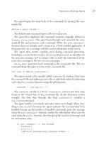
Figure 8-5 Elementary all-pass active RC network.
is at +180
◦
, according to the usual conventions [Dorf, 1990, Figs. 7-15b
and 7-16].
T(jω) =
jω − a
jω + a
, T(s)=
s − z
s + p
THE HILBERT TRANSFORM 147
Note the use of the Mathcad function atan2(x, y) that measures phase
out to ±180
◦
(see also Chapter 2). The values 0.0025 μF and 100 K
are modiÞed in each usage of this circuit. Metal Þlm resistors and stable
NP0 capacitors are used. The op-amp is of high quality because several
of them in cascade are usually dc coupled.
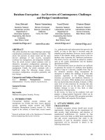
Figure 8-6 shows how these basic networks can be combined to produce
a wideband −90
◦
phase shift with small phase error and almost constant
amplitude over a baseband frequency range. Each of the two all-pass net-
works (I and Q) is derived from a computer program that minimizes
the phase error between the I and Q channels on two separate “wires.”
[Bedrosian, 1963] is the original and deÞnitive IRE article on this subject.
Examples of the circuit design and component values of RC op-amp net-
works are in [Williams and Taylor, 1995, Chap. 7] and numerous articles.
A simulation of this circuit from 300 to 3000 Hz using Multisim and the
values from the book of Williams and Taylor (p. 7.36) shows a maxi-
mum phase error of 0.4
◦
. The 6 capacitors are 1000 pF within 1.0%. The
input and output of each channel may require voltage-follower op-amps
to assure minimal external loading by adjacent circuitry. Copying R and
C values from a handbook in this manner is sometimes quite sensible
when the alternatives can be unreasonably labor- intensive. A high- speed
PC could possibly be used to Þne-tune the phase error in a particular appli-
cation (see, for example, [Cuthbert, 1987], and also Mathcad’s optimizing
algorithms).
-
+
−
+
R
R
Iout
Qou
t
16.2k
C
−
+
R
R
118k
C
−
+
−
+
R
R
511k
C
−
+
−
+
R
R
54.9k
C
−
+
R
R
267k
C
−
+
−
+
R
R
17.4Meg
C
R = 10k 1% C = 1000pF 1%
IN
90°
+
−
Figure 8-6 Two sets of basic all-pass networks create I and Q outputs
with a 90
◦
phase difference across the frequency range 300 to 3000 Hz.
148 DISCRETE-SIGNAL ANALYSIS AND DESIGN
The following brief discussion provides some examples regarding the
usage of the Hilbert transform and its mathematical equivalent in radio
equipment. Analog methods are used for visual convenience.
SSB TRANSMITTER
We illustrate in Fig. 8-7 the analog design of an SSB transmitter sig-
nal using the phase-shift method. It uses the −90
◦
lowpass (positive-
frequency) Þlter of Fig. 8-6, two double-balanced mixers, and an HF
local oscillator [Krauss et al., 1980, Chap. 8]. The mixers create two
double-sideband suppressed carrier (DSBSC) signals. The combiner at
the output uses the sum of these two inputs to create at the local oscil-
lator frequency ω
0
an LSB or the difference of the two inputs to create
an USB. The BPF restricts the output to some desired frequency band.
The end result is equivalent mathematically to a synthesis of the Hilbert
transform and the analytic signal translated to RF that we have considered
in this chapter.
There is an interesting artifact of this circuit that we should look at.
1. Start at the input, where the baseband signal is cos ω
m
t at 0
◦
refer-
ence.
2. The I -channel output (a) has a phase shift ∠θ
◦
, relative to the 0
◦
reference input, that varies from +64
◦
at 300 Hz to −154
◦
at 3 kHz.
The I -channel output (a) is cosω
m
t +θ
◦
. This effect is inherent in
the design of this Þlter.
USB
or
LSB
Outpu
t
L.O.
AF In
x(n)
+
+
−
Lowpass
Filter
Fig 8-6
90°
+
−
cos w
o
t
sin w
o
t
DSBSC mixer
DSBSC mixer
Q
I
q
q − 90°
(b)
(e)
(d )
(c)
(a)
−90°
Figure 8-7 SSB generator using the phasing method.
THE HILBERT TRANSFORM 149
3. Because the wideband phase shift from 300 to 3000 Hz is very nearly
−90
◦
from I to Q,theQ output (c) has the same additional shift θ
◦
as the I -channel output (a).
If we compare locations (a) and (c) we see that they differ only in
phase and not in frequency. So this process is not phase modulation,
which would have to be a nonlinear process that creates phase modula-
tion sidebands. It is an additive process that does not contribute additional
spectrum components. For a typical SSB speech signal this phase shift is
usually not noticed by a human listener, although some amplitude mod-
iÞcation (not the same as nonlinear distortion) can occur if the circuitry
is not almost linear-phase. It could be noticed in data modes that are not
normally used in SSB. The important thing is that the I and Q channels
are separated by very nearly 90
◦
, positive at the I channel and negative
at the Q channel.
In a DSP SSB transmitter an FIR design HT would need only a single
channel, located, for example, on the Q side [Sabin and Schoenike, 1998,
Chap. 8].
Also, other phase errors in the circuit can reduce the degree of cancel-
lation of the undesired sideband. A practical goal for this cancellation is
in the range 40 to 50 dB.
FILTER METHOD TRANSMITTER
Figure 8-8 shows the Þlter method of creating an SSB signal. The DSBSC
signal goes through a narrowband mechanical or crystal Þlter. The Þlter
creates the one-sided real SSB signal at IF, and the result is indistinguish-
able from the phasing method. Both methods are basically equivalent
mathematically in terms of the analytic signal [Carlson, 1986, Chap. 6].
In other words, the result of a frequency translation of the transmit signal
to baseband is indistinguishable from the analytic signal in Eq. (8-5.)
PHASING METHOD SSB RECEIVER
Figure 8-9 illustrates a phase-shift, image-canceling SSB receiver. It is
similar to the SSB transmitter except that two identical lowpass Þlters are
150 DISCRETE-SIGNAL ANALYSIS AND DESIGN
IF Ou
t
L.O.
AF In
DSBSC mixer
Mechanical
or
Crystal Filter
IF freq
Figure 8-8 SSB generator using the IF Þlter method.
AF Ou
t
IF in
Lowpass
Filter
Fig 8-6
I
mixer
Q mixer
Q
I
LPF
LPF
cos w
o
t
sin w
o
t
−90°
L.O.
90°
+
−
+
+
−
Figure 8-9 Phasing method image-canceling SSB demodulator.
used after the IF or RF down-conversion to baseband (especially in the
direct-conversion receiver) to establish the desired audio-frequency range
and attenuate undesired mixer outputs that can interfere with the desired
input frequency range. The lowpass Þlter of Fig. 8-6 provides the I and
Q audio. The combiner selects the USB or LSB mode. The mixers are
identical double-balanced types that perform the DSBSC function. Digital
circuitry that divides four times the desired L.O. frequency by four and
also provides two quadrature outputs, I
LO
and Q
LO
, is frequently used
[Sabin and Schoenike, 1998, Chap. 4], especially when the L.O. frequency
must be variable to cover an input signal range.
FILTER METHOD RECEIVER
Figure 8-8, ßipped from left to right, shows the receiver IF Þlter method.
The narrowband Þlter precedes the down-converter mixer. This method
is also equivalent to the phasing method, which has a possible advan-
tage in circuit cost, where crystal and mechanical Þlters are usually more