The Illustrated Network- P15 pps
Bạn đang xem bản rút gọn của tài liệu. Xem và tải ngay bản đầy đủ của tài liệu tại đây (204.63 KB, 10 trang )
CHAPTER
What You Will Learn
In this chapter, you will learn about the addressing used in IPv4 and IPv6. We’ll
assign addresses of both types to various interfaces on the hosts and routers of the
Illustrated Network. We’ll mention older classful IPv4 addressing and the current
classless system. We will start to explore the differences between IPv4 and IPv6
addressing and why both exist.
You will learn about the important concept of subnetting and supernetting
and other aspects of IP addressing. We’ll detail the IP subnet mask as well.
IPv4 and IPv6
Addressing
4
In many ways, IPv4 and IPv6 are distinct protocols with important differences. Never-
theless, both IPv4 and IPv6 are valid IP layer addresses, some networks use both IPv4
and IPv6, and the packet data content is the same in both. Network engineers often
deal with both every day, and we will too. In the future, the importance of IPv6 will
only grow.
IPv4 addressing was fairly straightforward to understand before the Internet
exploded all over the world. Then the original (“classful”) rules for assigning networks
IPv4 addresses didn’t work as well, and routers were getting overwhelmed by the size
and resources needed to maintain routing and forwarding tables.
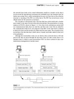
This chapter investigates both IPv4 and IPv6 addressing, and the host and router
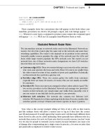
interfaces on the Illustrated Network have both IPv4 and IPv6 addresses (see
Figure 4.1). We’ll assign these addresses manually in this chapter.
We’ll start the discussion by describing the classless Internet routing (CIDR) rules
created so that we did not run out of IPv4 addresses in 1994, shortly after the Web
exploded onto the scene. Then we’ll describe the older classful system, and, fi nally,
we’ll talk about IPv6 addressing. This chapter also explores important aspects of IP
addressing subnetting and supernetting.
CE0
lo0: 192.168.0.1
fe-1/3/0: 10.10.11.1
MAC: 00:05:85:88:cc:db
(Juniper_88:cc:db)
IPv6: fe80:205:85ff:fe88:ccdb
P9
lo0: 192.168.9.1
PE5
lo0: 192.168.5.1
P4
lo0: 192.168.4.1
so-0/0/1
79.2
so-0/0/1
24.2
so-0/0/0
47.1
so-0/0/2
29.2
so-0/0/3
49.2
so-0/0/3
49.1
so-0/0/0
59.2
so-0/0/2
45.1
so-0/0/2
45.2
so-0/0/0
59.1
ge-0/0/3
50.2
ge-0/0/3
50.1
Ethernet LAN Switch with Twisted-Pair Wiring
bsdclient lnxserver wincli1
em0: 10.10.11.177
MAC: 00:0e:0c:3b:8f:94
(Intel_3b:8f:94)
IPv6: fe80::20e:
cff:fe3b:8f94
eth0: 10.10.11.66
MAC: 00:d0:b7:1f:fe:e6
(Intel_1f:fe:e6)
IPv6: fe80::2d0:
b7ff:fe1f:fee6
LAN2: 10.10.11.51
MAC: 00:0e:0c:3b:88:3c
(Intel_3b:88:3c)
IPv6: fe80::20e:
cff:fe3b:883c
LAN2: 10.10.11.111
MAC: 00:0e:0c:3b:87:36
(Intel_3b:87:36)
IPv6: fe80::20e:
cff:fe3b:8736
winsvr1
LAN1
Los Angeles
Office
Ace ISP
AS 65459
DSL Link
Wireless
in Home
Solid rules
ϭ
SONET/SDH
Dashed rules
ϭ
Gig Ethernet
Note: All links use 10.0.x.y
addressing only the last
two octets are shown.
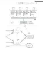
FIGURE 4.1
The Illustrated Network IP addressing, showing the interfaces on the LANs and customer-edge
routers that we will be working with. Note that in most cases, all of the network interfaces will
have both IPv4 and IPv6 addresses.
110 PART II Core Protocols
CE6
lo0: 192.168.6.1
fe-1/3/0: 10.10.12.1
MAC: 0:05:85:8b:bc:db
(Juniper_8b:bc:db)
IPv6: fe80:205:85ff:fe8b:bcdb
Ethernet LAN Switch with Twisted-Pair Wiring
bsdserver lnxclient winsvr2 wincli2
eth0: 10.10.12.77
MAC: 00:0e:0c:3b:87:32
(Intel_3b:87:32)
IPv6: fe80::20e:
cff:fe3b:8732
eth0: 10.10.12.166
MAC: 00:b0:d0:45:34:64
(Dell_45:34:64)
IPv6: fe80::2b0:
d0ff:fe45:3464
LAN2: 10.10.12.52
MAC: 00:0e:0c:3b:88:56
(Intel_3b:88:56)
IPv6: fe80::20e:
cff:fe3b:8856
LAN2: 10.10.12.222
MAC: 00:02:b3:27:fa:8c
IPv6: fe80::202:
b3ff:fe27:fa8c
LAN2
New York
Office
P7
lo0: 192.168.7.1
PE1
lo0: 192.168.1.1
P2
lo0: 192.168.2.1
so-0/0/1
79.1
so-0/0/1
24.1
so-0/0/0
47.2
so-0/0/2
29.1
so-0/0/3
27.2
so-0/0/3
27.1
so-0/0/2
17.2
so-0/0/2
17.1
so-0/0/0
12.2
so-0/0/0
12.1
ge-0/0/3
16.2
ge-0/0/3
16.1
Best ISP
AS 65127
Global Public
Internet
CHAPTER 4 IPv4 and IPv6 Addressing 111
IP ADDRESSING
In Chapter 2 we worked a lot with the Linux and Windows clients and servers. Let’s
start with our FreeBSD hosts and routers to look at IPv4 and IPv6 addresses on the
device’s interfaces.
Figure 4.1 shows through shading the portion of the network we’ll be working
with in this chapter. All of the ISP routers have IP addresses, of course, both IPv4 and
IPv6, but we’ll only look at the addressing of the customer routers. Although it can be
important, we won’t worry about the addressing used internally by service providers.
The things that can go wrong there are far beyond this introductory discussion.
When the Illustrated Network was fi rst confi gured, we manually assigned an IPv4
address to the bsdserver Ethernet interface (em0) with ifconfig. The only tricky part
was translating the prefi x length used on our network (/24) to a decimal network mask
for this host (this was done only to show this common method). We could have used
10.10.12.77/24 as well, or even hex (0xffffff00). We’ll talk about prefi x lengths and
network masks later on in this chapter. The ifconfig command generates no output,
but we can look at the result using ifconfig without any parameters.
bsdserver# ifconfig em0 inet 10.10.12.77 netmask 255.255.255.0
bsdserver# ifconfig
em0: flags=8843<UP,BROADCAST,RUNNING,SIMPLEX,MULTICAST> mtu 1500
options=3<RXCSUM,TXCSUM>
inet6 fe80::20e:cff:fe3b:8732%em0 prefixlen 64 scopeid 0x1
inet 10.10.12.77 netmask 0xffffff00 broadcast 10.10.12.255
ether 00:0e:0c:3b:87:32
media: Ethernet autoselect (100baseTX <full-duplex>)
status: active
Automatic IP Addressing
This chapter assigns IPv4 and IPv6 addresses manually on each device. This is still
done, but it is more common by far to assign IP addresses automatically with the
Dynamic Host Confi guration Protocol, or DHCP. Routers can use DHCP as well.
We’ll look at DHCP in a later chapter.
The interface fl ags are interpreted on the fi rst line of the output. Interface
em0 is up
and running, and can send or receive, but not at the same time (simplex). It can send
and receive broadcasts and multicast, and has a Maximum Transmission Unit (MTU)
of 1500 bytes (a normal Ethernet frame). If a packet is queued for output and is too
large for this 1500-byte frame, then the packet content must be fragmented into mul-
tiple frames, each in its own packet. We’ll talk about fragmentation in detail in a later
chapter. The option line says that the frame check sequence is generated when trans-
mitting and checked when receiving.
112 PART II Core Protocols
Note that we got an IPv6 address (the inet6 line) as well. This is called the link-
local (0xfe80) IPv6 address. It is based on the MAC address and generated automati-
cally, with a prefi x length (
prefixlen) of /64. Newer versions of FreeBSD function
this way, as long as the local router is properly confi gured to run IPv6. You can use
the ifconfig command with the inet6 option to assign a specifi c IPv6 address to the
interface. (There’s a lot more to IPv6 addressing, such as router-assigned prefi xes, but
we’re keeping it very basic here.)
The next line lists the IPv4 address, netmask, and the address used as an IP broad-
cast address to send packets to every device on the network. The MAC address has a
line all its own, followed by the type of media: 100-Mbps, twisted-pair Ethernet, capable
of sending and receiving (full-duplex) at the same time (but em0 will not do that). The
interface is active as well as up, which means that it is sending and receiving bits.
Linux uses slightly different syntax to assign IPv4 addresses to interfaces. Let’s assign
an IPv4 address to the lnxclient Ethernet interface (eth0) using ifconfig. In this case,
the network mask format is easier to read. We’ll look at the interface before the address
is assigned, and then after, and fi nd something very different from FreeBSD with regard
to the network broadcast address.
[root@lnxclient admin]# ifconfig
eth0 Link encap:Ethernet HWaddr 00:B0:D0:45:34:64
UP BROADCAST RUNNING MULTICAST MTU:1500 Metric:1
RX packets:43993 errors:0 dropped:0 overruns:1 frame:0
TX packets:0 errors:0 dropped:0 overruns:0 carrier:0
collisions:0 txqueuelen:100
RX bytes:7491082 (7.1 Mb) TX bytes:0 (0.0 b)
Interrupt:5 Base address:0xec00
[root@lnxclient admin]# ifconfig eth0 10.10.12.166 netmask 255.255.255.0
[root@lnxclient admin]# ifconfig
eth0 Link encap:Ethernet HWaddr 00:B0:D0:45:34:64
inet addr:10.10.12.166 Bcast:10.255.255.255 Mask:255.255.255.0
UP BROADCAST RUNNING MULTICAST MTU:1500 Metric:1
RX packets:44000 errors:0 dropped:0 overruns:1 frame:0
TX packets:0 errors:0 dropped:0 overruns:0 carrier:0
collisions:0 txqueuelen:100
RX bytes:7492614 (7.1 Mb) TX bytes:0 (0.0 b)
Interrupt:5 Base address:0xec00
This output gives much the same information as FreeBSD, but provides more details
for traffi c statistics and error conditions. The last line of output gives details about how
the interface card communicates with the operating system and has nothing directly
to do with the network. Note that no automatic IPv6 addresses are generated. All ver-
sions of the Linux kernel newer than 2.2, regardless of distribution, now support ways
to give an interface an IPv6 address, but we will not do that.
However, Linux has also done something very odd with the broadcast address. We’ll
talk more about broadcast address formats later in this chapter, but it is supposed to be
formed by setting all of the host bits that follow the network bits in the IP address to 1.
CHAPTER 4 IPv4 and IPv6 Addressing 113
Now, we set a network mask for 24 bits (255.255.255.0), but Linux has set all the bits in
the fi eld to a string of 1 bits in the broadcast mask to the last 24 bits of the IPv4 address,
or
10.255.255.255. As we saw with FreeBSD, the correct broadcast address for this net-
work mask should be 10.10.12.255.
This means, as we’ll soon discover, that this older version of Linux expects classful
IPv4 addresses, and today we mostly use classless IPv4 addresses. (There was some
debate as to whether this was a “broken” version or install, but the behavior is consis-
tent and all else seems well.)
To fi x the broadcast address so that the network functions properly (yes, it mat-
ters), we’ll have to specify a broadcast address for lnxclient (and do the same for
lnxserver).
[root@lnxclient admin]# ifconfig eth0 broadcast 10.10.12.255
[root@lnxclient admin]# ifconfig
eth0 Link encap:Ethernet HWaddr 00:B0:D0:45:34:64
inet addr:10.10.12.166 Bcast:10.10.12.255 Mask:255.255.255.0
UP BROADCAST RUNNING MULTICAST MTU:1500 Metric:1
RX packets:44000 errors:0 dropped:0 overruns:1 frame:0
TX packets:0 errors:0 dropped:0 overruns:0 carrier:0
collisions:0 txqueuelen:100
RX bytes:7492614 (7.1 Mb) TX bytes:0 (0.0 b)
Interrupt:5 Base address:0xec00
Let’s move on to the Windows devices. In Windows, IPv4 and IPv6 address assign-
ment can be awkward. In Windows XP, you typically use the graphical interface to assign
IPv4 addresses, subnet masks, and default gateways. The method is well-documented
in many places and need not be detailed here. You can easily view the current IP
addresses by running the Windows ipconfig command. Here’s the result on wincli2.
Microsoft Windows XP [Version 5.1.2600]
(C) Copyright 1985-2001 Microsoft Corp.
C:\Documents and Settings\Owner>ipconfig
Windows IP Configuration
Ethernet adapter Local Area Connection:
Connection-specific DNS Suffix . :
IP Address . . . . . . . : 10.10.12.222
Subnet Mask . . . . . . . : 255.255.255.0
Default Gateway . . . . . . : 10.10.12.1
Unlike the Unix-based output, Windows XP associates a default gateway with the
interface. This information is properly part of the host routing and forwarding routing
table, and we’ll talk more about default gateways in a later chapter on routing.
How can we give the LAN interface an IPv6 address? In XP, the graphical version
depends on the service packs installed. The easiest way is to use the command prompt
to fi rst install the IPv6 protocol stack as a dual stack on the host. XP can generate
a series of IPv6 addresses automatically as well (you can also set them manually). It
should be noted that in Vista, IPv6 is typically turned on by default.
114 PART II Core Protocols
C:\Documents and Settings\Owner>ipv6 install
Installing. . .
Succeeded.
C:\Documents and Settings\Owner>
Once IPv6 support is available, the output of the ipconfig command shows some
very interesting things.
C:\Documents and Settings\Owner>ipconfig
Windows IP Configuration
Ethernet adapter Local Area Connection:
Connection-specific DNS Suffix . :
IP Address . . . . . . . : 10.10.12.222
Subnet Mask . . . . . . . : 255.255.255.0
IP Address . . . . . . . : fe80::202:b3ff:fe27:fa8c%4
Default Gateway . . . . . . : 10.10.12.1
Tunnel adapter Automatic Tunneling Pseudo-Interface:
Connection-specific DNS Suffix . :
IP Address . . . . . . . : fe80::5efe:10.10.12.222%2
Default Gateway . . . . . . :
Not only has the IPv6 installation created an IPv6 address for the LAN interface, it is a
site-local address based on the MAC address of the interface (see Chapter 3). The “%”
number is just an index for the order in which certain types of IPv6 addresses were
generated by the IPv6 installation.
On working networks, more than just the automatic tunnel IPv6 address is usually
created. It is not unusual to see a Tunnel adapter Teredo Tunneling Pseudo-Interface.
Teredo is a Microsoft initiative, defi ned in RFC 3904, that allows devices to reach the
IPv6 Internet from behind a network address translation (NAT) device. There is often
a Tunnel adapter 6to4 Tunneling Pseudo-Interface as well, depending on how the
routers are confi gured. A full discussion of these Windows IPv6 interfaces is beyond the
scope of this book, but we’ll discuss IPv6 tunneling in more detail in Chapter 9.
The customer edge routers are Juniper Networks routers. The confi guration fi les on
these routers look very different from those on a Cisco router. Juniper Networks router
confi gurations are more like C language programs and are organized with braces in
indented stanzas. However, Juniper Networks router confi gurations can be rendered
in “set” language that looks more like Cisco’s style. For example, on router CE0, the
addressing on interface fe-1/3/0 is more complex than on a host:
admin@CE0> show interface fe-1/3/0
unit 0 {
family inet {
address 10.10.11.1/24;
}
CHAPTER 4 IPv4 and IPv6 Addressing 115
family inet6 {
address FC00:ffb3:d5:b:205:85ff:fe88:ccdb/64;
}
}
user@CE0>
In this format, all statements confi gured under another statement (indented) apply
to that higher level statement. Thus, both family inet and family inet6 apply to
unit 0, but only the address 10.10.11.1/24 applies to family inet. The form is used
often in this book, and becomes more familiar with repetition.
This form can also be shown in the following more compact format, which is the
style we will use in this book:
admin@CE0> set interface fe-1/3/0 unit 0 family inet address 10.10.11.1/24;
admin@CE0> set interface fe-1/3/0 unit 0 family inet6 address
FC00:ffb3:d5:b:205:85ff:fe88:ccdb/64;
This output is for logical unit 0, the simplest case. Juniper Networks router interfaces
can have logical units numbered from 0 to 65535, and each can have more than one
IPv4 or IPv6 address. The LAN interface on CE6 looks very much the same, except for
the address specifi cs.
We’ll talk about the specifi cs of the IPv4 and IPv6 address formats, network marks,
and prefi x lengths, and other topics, in the rest of this chapter. At the end, we’ll see just
what the complex IPv6 address format is telling us about the Illustrated Network.
One type of address we won’t be exploring in this chapter is the anycast address.
To understand anycast addresses, consider that there are three major types of IP
addresses.
Unicast—This type of IP address is used to identify a single network interface.
It establishes a one-to-one relationship between the network address and
network endpoint (interface). So each unicast address uniquely identifies a
network source or destination.
Broadcast/Multicast—This type of IP address is used to identify a changeable
group of interfaces. Broadcast addresses are used to send a message to every
reachable interface, and broadcast domains are typically defined physically.
Multicast addresses are not limited to a single domain and multicast groups
are established logically. IPv6 relies on multicast addresses for many of the
discovery features of IPv6 and things that are done with broadcasts in IPv4.
In both multicast and broadcast, there is a many-to-one association between
network address and network endpoints. Consequently, one address identifies
a group of network endpoints, and information is replicated by routers to
reach them all.
Anycast—This type of IP address, formally defined in IPv6, is used to identify a
defined set of interfaces, usually on different devices. Anycast addresses are
116 PART II Core Protocols
used to deliver packets to the “nearest” interface, where nearness is defined
as a routing parameter. The same can be done in IPv4, but not as elegantly.
However, multicasts deliver to many interface destinations, while anycasts
deliver to only one, although many might be reachable. Anycasts are useful for
redundancy purposes, so servers can exist around the world, all with the same
address, but traffic is only sent to the one that is the “closest” to the source.
This book uses mainly unicast IP addresses. Multicast and anycast addresses will be
introduced and used as necessary.
THE NETWORK/HOST BOUNDARY
We just saw that the mask determines where the boundary between the network
and host portions of the IP address lies. This boundary is important: If it is set too far
to the right, there are lots of networks, but none of them can have many hosts. If it
is set too far to the left, then there are plenty of hosts allowed, but fewer networks
overall.
In IP, the address boundary is moveable, and always has been. But in the past, right
through the big Internet explosion in the mid-1990s, the network/host boundary in
IPv4 could only be in one of three places. This produced lots of networks that were too
small in terms of hosts, and many that were far too large, capable of holding millions
of hosts. Not only that, but there were so many small networks, each of which needing
a separate routing table entry in each and every core Internet router, that the Internet
threatened to drown under its own weight.
In a nutshell, the inability to aggregate Class C blocks drove routing table pressure
and the unsustainable rate of allocation of Class A and Class B addresses. This would
have caused IPv4 exhaustion by 1994 to 1995, as projected in 1990.
So the rules were changed to allow the network/host boundary in IPv4 and IPv6
addresses to be set almost anywhere (there are still some basic rules). When applied
to the former, fi xed, IPv4 octet boundaries, if you moved the “natural” boundary
of the mask to the right of its normal position, this was called subnetting and
the address space gets smaller. (Actually, even the older “natural” IPv4 addresses
could always be subnetted.) And if you moved the “natural” boundary of the mask
to the left of its normal position, this was called supernetting and the address space
became larger.
In this chapter, we will talk about subnetting and supernetting in detail. Supernet-
ting is more commonly called “aggregation” today, but we’ll call it supernetting in this
chapter just to make the contrast with subnetting explicit. We will also talk about the
current system of rules for hosts and routers concerning the positioning of the bound-
ary between the network and host portion of the IP address, variable-length subnet
masking (VLSM), and classless interdomain routing (CIDR). But fi rst, let’s look at the
IPv4 address in detail.
CHAPTER 4 IPv4 and IPv6 Addressing 117
THE IPV4 ADDRESS
The IPv4 address is a network layer concept and has nothing to do with the addresses
that the data link layer uses, often called the hardware address on LANs. IPv4 addresses
must be mapped to LAN hardware addresses and WAN serial link addresses. However,
there is no real relationship between LAN media access control (MAC) or WAN serial
link addresses in the frame header and the IPv4 addresses used in the packet header,
with the special exception of multicast addresses.
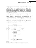
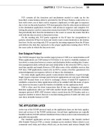
The original IPv4 addressing scheme established in RFC 791 is known as classful
addressing. The 32 bits of the IPv4 address fall into one of several classes based on
the value of the initial bits in the IPv4 address. The major classes used for addresses
were A, B, and C. Class D was (and is) used for IPv4 multicast traffi c, and Class E was
“reserved” for experimental purposes. Each class differs in the number of IPv4 address
bits assigned to the network and the host portion of the IP address. This scheme is
shown in Figure 4.2.
Note that with Class A, B, and C, we are referring to the size of the blocks being allo-
cated as well as the region from which they were allocated by IANA. However, Classes
D and E refer to the whole respective region. Multicast addresses, when they were
assigned for applications, for example, were assigned one at a time like (for instance)
port numbers. (We’ll talk about port numbers in a later chapter.) In the rest of this
chapter, references to Classes A, B, and C are concerned with address space sizes and
not locations.
The 4 billion (actually 4,294,967,296) possible IPv4 addresses are split up into fi ve
classes. The fi ve classes are not equal in size, and Class A covers a full half of the whole
32-bit Address Starts with:
Class A
Class B
Class C
Class D
Class E
0 (0–127)
10 (128–191)
110 (192–223)
1110 (224–239)
1111 (240–255)
First
byte
Second
byte
Third
byte
Fourth
byte
Number of
Addresses:
% of
Address Space
2
31
5 2,147,483,648
2
30
5 1,073,741,824
2
29
5 536,870,912
2
28
5 268,435,456
2
28
5 268,435,456
50
25
12.5
6.25
6.25
FIGURE 4.2
Classful IPv4 addressing, showing the number of addresses possible and percentage of the total
address space for each class. Class D is still the valid IPv4 address range used for multicasting.
118 PART II Core Protocols