The Illustrated Network- P23 docx
Bạn đang xem bản rút gọn của tài liệu. Xem và tải ngay bản đầy đủ của tài liệu tại đây (417.98 KB, 10 trang )
CHAPTER
What You Will Learn
In this chapter, you will learn about ICMP messages, their types, and (in many
cases) the codes used in each type. We’ll look at which ICMP messages are routinely
blocked at fi rewalls and which are essential for proper device operation.
You will learn about the common ping utility for determining device accessibility
(“reachability”) on an IP network. We’ll discuss the mechanics of both ping and
traceroute, and use several ping examples to illustrate ICMP on the network.
Internet Control Message
Protocol
7
The only function of the IP layer is to provide addressing for and route the IP packet.
That’s all. Once an IP packet has been dealt with, the IP layer just looks for the next
packet. But IP is a connectionless, “best effort,” or “unreliable” method of packet
delivery. The terms “best effort” and “unreliable” often make it sound like IP is casual
about the delivery of packets, which is why they are in quotes so that no one takes
them too literally. IP’s best effort is usually just fi ne, given the low error rates on modern
transports, and it is mostly unreliable with regard to a lack of guarantees, as has been
pointed out. Besides, there is nothing wrong with letting other layers, such as the TCP
segments or the Ethernet frames, have the major responsibility for error detection and
correction.
This is not to say that IP should be oblivious to errors. The network layer, in its ubiq-
uitous and key position at the heart of the protocol stack, should know about packet
errors and is in a good position to let layers above know what’s going on (although IP
lets the upper layers decide what to do about the condition).
And there’s plenty that can still go wrong, and not just with regard to bit errors.
A packet might wander the router cloud until the TTL fi eld hits zero. A destination
server might be down. A destination server might no longer exist. The “do not frag-
ment” bit might forbid fragmentation when it is needed to send a packet, stopping the
routing process cold. In all of these situations, the sender should be informed of the
condition.
CE0
lo0: 192.168.0.1
fe-1/3/0: 10.10.11.1
MAC: 00:05:85:88:cc:db
(Juniper_88:cc:db)
IPv6: fe80:205:85ff:fe88:ccdb
P9
lo0: 192.168.9.1
PE5
lo0: 192.168.5.1
P4
lo0: 192.168.4.1
so-0/0/1
79.2
so-0/0/1
24.2
so-0/0/0
47.1
so-0/0/2
29.2
so-0/0/3
49.2
so-0/0/3
49.1
so-0/0/0
59.2
so-0/0/2
45.1
so-0/0/2
45.2
so-0/0/0
59.1
ge-0/0/3
50.2
ge-0/0/3
50.1
Ethernet LAN Switch with Twisted-Pair Wiring
bsdclient lnxserver wincli1
em0: 10.10.11.177
MAC: 00:0e:0c:3b:8f:94
(Intel_3b:8f:94)
IPv6: fe80::20e:
cff:fe3b:8f94
eth0: 10.10.11.66
MAC: 00:d0:b7:1f:fe:e6
(Intel_1f:fe:e6)
IPv6: fe80::2d0:
b7ff:fe1f:fee6
LAN2: 10.10.11.51
MAC: 00:0e:0c:3b:88:3c
(Intel_3b:88:3c)
IPv6: fe80::20e:
cff:fe3b:883c
LAN2: 10.10.11.111
MAC: 00:0e:0c:3b:87:36
(Intel_3b:87:36)
IPv6: fe80::20e:
cff:fe3b:8736
winsvr1
LAN1
Los Angeles
Office
Ace ISP
AS 65459
DSL Link
Wireless
in Home
Solid rules ϭ SONET/SDH
Dashed rules
ϭ
Gig Ethernet
Note: All links use 10.0.x.y
addressing only the last
two octets are shown.
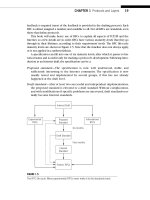
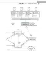
FIGURE 7.1
ICMP is used on all devices on the Illustrated Network, routers, and hosts. In this chapter,
we’ll work with the hosts on the LANs.
190 PART II Core Protocols
CE6
lo0: 192.168.6.1
fe-1/3/0: 10.10.12.1
MAC: 0:05:85:8b:bc:db
(Juniper_8b:bc:db)
IPv6: fe80:205:85ff:fe8b:bcdb
Ethernet LAN Switch with Twisted-Pair Wiring
bsdserver lnxclient winsvr2 wincli2
eth0: 10.10.12.77
MAC: 00:0e:0c:3b:87:32
(Intel_3b:87:32)
IPv6: fe80::20e:
cff:fe3b:8732
eth0: 10.10.12.166
MAC: 00:b0:d0:45:34:64
(Dell_45:34:64)
IPv6: fe80::2b0:
d0ff:fe45:3464
LAN2: 10.10.12.52
MAC: 00:0e:0c:3b:88:56
(Intel_3b:88:56)
IPv6: fe80::20e:
cff:fe3b:8856
LAN2: 10.10.12.222
MAC: 00:02:b3:27:fa:8c
IPv6: fe80::202:
b3ff:fe27:fa8c
LAN2
New York
Office
P7
lo0: 192.168.7.1
PE1
lo0: 192.168.1.1
P2
lo0: 192.168.2.1
so-0/0/1
79.1
so-0/0/1
24.1
so-0/0/0
47.2
so-0/0/2
29.1
so-0/0/3
27.2
so-0/0/3
27.1
so-0/0/2
17.2
so-0/0/2
17.1
so-0/0/0
12.2
so-0/0/0
12.1
ge-0/0/3
16.2
ge-0/0/3
16.1
Best ISP
AS 65127
Global Public
Internet
CHAPTER 7 Internet Control Message Protocol 191
Without error condition feedback from the network, the natural response to an
unexpected result (in this case, a reply) is to simply repeat the original message. Some-
times this might work, especially if the condition is transient, but semipermanent or
permanent error conditions must be reported to the source. Otherwise, repetitive
sending might result in an endless error loop, and certainly adds unnecessary traffi c
loads to the network.
This chapter explores aspects of IP’s built-in error reporting protocol, the Internet
Control Message Protocol (ICMP). Note that ICMP does not deal with “error messages,”
but “control messages,” a better term to cover all of the roles that have evolved for
ICMP. We’ll start by looking at one indispensable utility used on all TCP/IP network:
ping. We’ll be using the same LAN-based hosts as in the previous chapter, as shown in
Figure 7.1.
ICMP AND PING
The easiest way to look at ICMP on the Illustrated Network is with ping and traceroute.
Both utilities have been used before in this book, but because traceroute will be used
again in the chapters on routing, this chapter will use ICMP and ping.
The ping utility is just a way to “bounce” packets off a target device and see if it is
there—that is, it has the IP address that was provided, is powered on, and alive. The
device might still not function in the correct way (i.e., the router might not be rout-
ing properly), but at least the device is present and accounted for. It is routine to ping
a newly installed device, host, router, or anything else, just to see if it responds. If it
doesn’t, network administrators have a place to start troubleshooting.
Let’s use ping from the lnxclient to the bsdserver, both on LAN2 to start exploring
ICMP. Windows XP only sends four pings by default, but Unix systems will just keep
going until stopped with ^C (which is what was done here).
[root@lnxclient admin]# ping 10.10.12.77
PING 10.10.12.77 (10.10.12.77) 56(84) bytes of data.
64 bytes from 10.10.12.77: icmp_seq=1 ttl=64 time=0.549 ms
64 bytes from 10.10.12.77: icmp_seq=2 ttl=64 time=0.169 ms
64 bytes from 10.10.12.77: icmp_seq=3 ttl=64 time=0.171 ms
64 bytes from 10.10.12.77: icmp_seq=4 ttl=64 time=0.187 ms
64 bytes from 10.10.12.77: icmp_seq=5 ttl=64 time=0.216 ms
^C
10.10.12.77 ping statistics
5 packets transmitted, 5 received, 0% packet loss, time 3996ms
rtt min/avg/max/mdev = 0.169/0.258/0.549/0.146 ms
[root@lnxclient admin]#
The output shows the ICMP sequence numbers and round-trip time (rtt) for the
group in terms of minimum, average, maximum, and even the maximum deviation from
the mean. We do not have DNS on the network, so we have to use IP addresses. Most
192 PART II Core Protocols
ping implementations will accept host names, and some (such as Cisco routers) will
even do a reverse DNS lookup when given an IP address and report the host name
in the result. This can be very helpful when an IP address is entered incorrectly or
assigned to a different device than anticipated.
We can look at the ICMP packets used with ping in more detail. Let’s use both LANs
this time, and ping from
wincl1 (10.10.11.51) on LAN1 to wincli2 (10.10.12.222) on
LAN2. With XP, we won’t have to worry about stopping the sequence.
C:\Documents and Settings\Owner> ping 10.10.12.222
Pinging 10.10.12.222 with 32 bytes of data:
Reply from 10.10.12.222: bytes=32 time<1ms TTL=126
Reply from 10.10.12.222: bytes=32 time<1ms TTL=126
Reply from 10.10.12.222: bytes=32 time<1ms TTL=126
Reply from 10.10.12.222: bytes=32 time<1ms TTL=126
Ping statistics for 10.10.12.222:
Packets: Sent = 4, Received = 4, Lost = 0 (0% less),
Approximate round-trip times in milliseconds:
Minimum = 0ms, Maximum = 0ms, Average = 0ms
Due to the way the Windows operating systems handle timing, it’s not unusual to have
RTTs of 0.
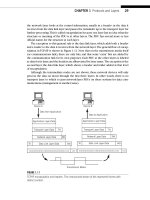
What does this group of packets look like at the target? Figure 7.2 shows us.
We can see that the four pings are accomplished with eight packets sent over the
network. Look at the last column in the upper part of the fi gure. Ping employs messages
in request–reply pairs using the ICMP protocol. An Echo request is sent out which
basically tells the receiver to “send an ICMP Echo message back to me, okay?” Once
the reply is received, the next request is sent, statistics compiled as the procedure goes
along, and so on.
The details of Frame 1 show that the ICMP message is carried directly inside an IP
packet (and then Ethernet II frame). But ICMP is not often shown as a transport layer
protocol. That would make ICMP function at the same level as things like TCP and
UDP, and this is simply not true. ICMP, as we will fi nd, is concerned with network layer
problems, so portraying ICMP as a type of special protocol associated with IP is not
really a mistake.
So technically, because IPv4 packets carry ICMP messages as protocol number 1,
ICMP is as valid a layer above IP as TCP or UDP or any other of the 200 or so defi ned
IP protocols that can be carried inside IP packets. But because every IP implementa-
tion must include ICMP (and IPv6 has ICMPv6), it makes sense to bundle ICMP and IP
together. This also implies that ICMP messages do not report their own errors.
What if no reply is received by the source of a ping? The source then times out
and another ICMP Echo request message is sent. Naturally, no statistics can be gener-
ated, and we get a “host unreachable” message in most cases. We can force a timeout
simply by trying to ping a nonexistent address (this could also be the result of a
simple typo).
CHAPTER 7 Internet Control Message Protocol 193
[root@lnxclient admin]# ping 10.10.12.55
PING 10.10.12.55 (10.10.12.55) 56(84) bytes of data.
From 10.10.12.166 icmp_seq=1 Destination Host Unreachable
From 10.10.12.166 icmp_seq=2 Destination Host Unreachable
From 10.10.12.166 icmp_seq=3 Destination Host Unreachable
10.10.12.55 ping statistics
3 packets transmitted, 0 received, +3 errors, 100% packet loss, time 5022ms,
pipe 3
[root@lnxclient admin]#
Many ping implementations report either “unreachable” or “unknown” errors. The
unreachable report implies that the target was once known to the source and reach-
able, but isn’t “reachable” at the moment. The unknown report implies that the source
has never heard of the target address or port. However, unreachable reports are often
returned by a host source pinging a new device, which obviously should be unknown.
FIGURE 7.2
Ping ICMP requests and replies showing details of the ping echo request in the middle pane. Note
that the content of the packet is the ICMP message, not TCP or UDP.
194 PART II Core Protocols
Most network people treat both error condition reports the same way: Something is
just plain wrong.
Ping remains the fi rst choice for checking connectivity on the Internet, between
hosts, and between host and router. On LANs, the fi rst troubleshooting step is “can
you ping it?” If you cannot, there’s no sense of going further. If you can, and things like
applications still do not function as expected, at least the troubleshooting process can
continue productively.
Firewalls sometimes screen out ICMP messages in the name of security. In these
cases, even a failed ping does not prove that a device is not working properly. How-
ever, diagnostics become more complex, although not impossible. Of course, screening
out all ICMP messages from a site usually also eliminates correct error reporting and
proper operation of the device. After we list the ICMP message types, we’ll discuss
which ICMP messages are essential.
Ping works with IPv6, too. On most Unix hosts, it’s called
ping6. When used with the
special IPv6 multicast address ff02::1, the %em0 addition probes for the IPv6 address of
every interface on the LAN, a form of forced neighbor discovery in IPv6. Here’s what it
looks like on LAN2 when run from the bsdserver.
bsdserver# ping6 ff02::1%em0
PING6(56=40+8+8 bytes) fe80::20e:cff:fe3b:8732%em0 —> ff02::1%em0
16 bytes from fe80::20e:cff:fe3b:8732%em0, icmp_seq=0 hlim=64 time=0.154 ms
16 bytes from fe80::202:b3ff:fe27:fa8c%em0, icmp_seq=0 hlim=128 time=0.575
ms(DUP!)
16 bytes from fe80::5:85ff:fe8b:bcdb%em0, icmp_seq=0 hlim=64 time=1.192
ms(DUP!)
16 bytes from fe80::20e:cff:fe3b:8856%em0, icmp_seq=0 hlim=64 time=0.097
ms(DUP!)
^C
—- ff02::1%em0 ping6 statistics —-
1 packets transmitted, 1 packets received, +3 duplicates, 0% packet loss
round-trip min/avg/max/std-dev = 0.071/2.520/39.406/8.950 ms
bsdserver#
All four systems on LAN2 are listed, except for lnxclient, which does not have an
IPv6 address. But hosts winsrv2 (fe80::20e:cff:fe3b:8856), wincli2 (fe80::202:b3ff:
fe27:fa8c), router TP6 (fe80::5:85ff:fe8b:bcdb), and even bsdserver (fe80::20e:
cff:fe3b:8732) itself have all replied. Oddly, the Windows XP client replies with a hop
limit of 128.
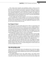
IPv6 traffi c (and ICMPv6) is also visible to Ethereal, so we can explore the for-
mat of these packets a little further. Figure 7.3 shows how the exchange of the ping6
ff02::1%em0 packets looks like from wincli2 when run from bsdserver. Note that this
only captures the exchange of packets that wincli2 processes.
CHAPTER 7 Internet Control Message Protocol 195
IPv6 uses its own version of ICMP, called (not surprisingly) ICMPv6. The ICMPv6
Echo reply message, sent in response to the ping to multicast group ff02::1, is high-
lighted in the fi gure. From the source address, we can tell this is from wincli2. We
looked at the details of the IPv6 header in the last chapter. Note that the hop limit is
128 in the reply, and that the protocol number for ICMP is 0x3a (58 decimal).
THE ICMP MESSAGE FORMAT
ICMP is usually considered to be part of the IP layer itself, and that is how ICMP is pre-
sented here. Hosts are supposed to set the IPv4 packet header TOS fi eld to 0 if the packet
carries an ICMP message, and routers are supposed to set the precedence fi eld to 6 or 7.
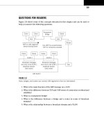
Figure 7.4 shows the format of two ICMP messages. All ICMP messages start with
the same three fi elds: an 8-bit Type and Code, followed by a 16-bit Checksum. Then,
depending on the value of the Type, the details of what follows varies. So to be more
informative, a second ICMP message is shown. The second message displays the format
used for a very common network condition, Destination Unreachable, which we saw
earlier.
FIGURE 7.3
ICMPv6 capture showing the ICMPv6 echo reply message from wincli2. The header details are
shown in the middle pane.
196 PART II Core Protocols
Destinations on a TCP/IP network can be unreachable for a number of reasons. The
host could be down, or have a new IP address that is not yet known to all systems. The
destination’s Internet name could have been typed incorrectly (but still maps to an
existing IP address), the only link to the site could have failed, and so on.
ICMP Message Fields
The fi elds that appear in all ICMP messages follow:
Type—This 8-bit field defines the major purpose of the ICMP message. Most
indicate error conditions, but two of the most common type values, 8 and 0,
mean Echo Request and Echo Reply, respectively. A Type value of 3 means Des-
tination Unreachable. All Types determine the format of the rest of the ICMP
message beyond the first three fields.
Code—This 8-bit field gives additional information about the condition in the
Type field. This is often not necessary, and many Types have only a Code = 0
defined. Other Types have many Code values defined to allow the source to
1 byte 1 byte 1 byte 1 byte
ChecksumCode
ICMP Data
(content and format depends on Type)
(a)
(b)
Type
ChecksumCode
Unused (all 0 bits)
IP Header (20 bytes)
and
First 8 bytes of Original Packet Data (usually TCP/UDP header)
Type 3
1 byte 1 byte 1 byte 1 byte
FIGURE 7.4
ICMP message format, showing how a specifi c message such as Destination Unreachable uses
the fi elds following the initial three. (a) General format of ICMP message. (b) Format of Destination
Unreachable ICMP message.
CHAPTER 7 Internet Control Message Protocol 197
focus on the real problem. For example, Destination Unreachable (Type = 3)
has 16 codes (0–15) defined.
Checksum—This is the same type of checksum as used for the IP packet header.
This points out that ICMP, although considered part of IP itself, is really just as
much a separate layer as anything else in TCP/IP and so must provide for its
own error checking.
ICMP Types and Codes
There are about 40 defi ned ICMP message types, and message types 41 through 255 are
reserved for future use. Only a handful of the types have more than a Code value of 0
defi ned, but these are the more important ICMP message types.
There are two major categories of ICMP messages: error messages (reports that do
not expect a response) and queries (messages sent with the expectation of a match-
ing response). Some others do not fall neatly into either category. The structure of
the fi elds following the checksum depends on the type of ICMP message. These two
formats are shown in Figure 7.5.
Note that the Destination Unreachable format shown in Figure 7.4 is an ICMP error
message and does not generate a reply. The fi elds that appear following the initial three
in the ICMP Destination Unreachable message are very common.
Unused—This 32-bit field must be set to all 0 bits for Destination Unreachable,
but in other ICMP messages it is often used as a sequence number to allow
requests and responses to be coordinated by senders and receivers.
IP Header and More—The last 28 bytes of the ICMP Destination Unreachable
message consist of the original IP header (usually 20 bytes, but can be up to
60 bytes) and the first 8 bytes of the segment inside the packet. Usually, this
includes the ports used by the TCP or UDP segment. This practice allows send-
ers to realize exactly what field value is objectionable. It’s one thing to say
“Port unreachable,” but better to say “Hey! The port in the UDP segment you
sent, which is port 6735, can’t be reached here right now ”
Usually, the error messages have the all-zero unused byte followed by the 28-byte
header and packet data, but not always. Identifi ers track Query message request/
response pairs, and the sequence numbers help sort out queries sent by the same
process (the process identifi er, the PID, is often the ICMP Query identifi er in Unix
systems).
The suite of the 40 ICMP message types can be implemented by hosts or rout-
ers. Some of the types are mandatory, some are optional, some are for experimental
use, and some are obsolete. In some cases, specifi cations explicitly state that hosts
or routers be able to transmit and receive (process) ICMP messages, but not in all
cases.
198 PART II Core Protocols