The Illustrated Network- P29 ppsx
Bạn đang xem bản rút gọn của tài liệu. Xem và tải ngay bản đầy đủ của tài liệu tại đây (352.83 KB, 10 trang )
(called VTY lines on a Cisco router), with a more secure remote access program called
secure shell (SSH), using a Web browser (HTTP is the protocol), or with SNMP (Sim-
ple Network Management Protocol), a protocol invented expressly for remote router
management.
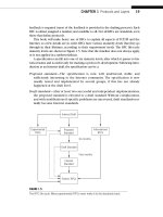
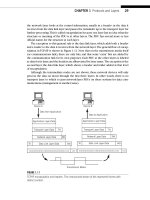
These arrangements are shown in Figure 9.4. Small routers usually only have a con-
sole port. With the proper cables, these console ports can be hooked up to a modem
for remote access, but obviously cannot be used simultaneously for local access. On
some routers, the console ports are labeled “Admin” or “Management.” It is tempting to
try and access a console or AUX ports using the normal graphical interface provided by
Windows, a Mac, or Unix X-Windows. But the console and AUX ports only understand a
simple, character-based serial protocol. On Windows PCs, for example, only HyperTer-
minal (or another serial terminal emulation program) can communicate with a router
through the console or AUX ports.
FORWARDING TABLE LOOKUPS
In the connectionless, best-effort world of IP, every packet is forwarded independently,
hop by hop, toward the destination. Each router determines the next hop for the
destination address in the packet header based on information gathered into the rout-
ing table and distilled into the forwarding table. The essential operation of a router
is the looking up of the packet’s destination IP address in this table to determine the
next hop.
Router
Console
Port
AUX
Port
Network
Interface
Local
Cable
Modem
Modem
Dial-up
Management
Terminal
Management
Terminal
Management
Terminal
Telnet, HTTP, SNMP
Network
FIGURE 9.4
The three router access methods. Note that the console port requires access to the router, while
the others allow remote access.
CHAPTER 9 Forwarding IP Packets 249
It’s unusual that a packet address is an exact match for a table entry. Otherwise,
routing and forwarding tables would need an entry for every host in the world—all
32 bits for IPv4 and 128 bits for IPv6! So in the current classless (prefi x) world of IP
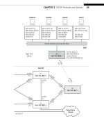
addressing, the host-hop destination is chosen by the longest match rule. Figure 9.5
shows how the next-hop address and interface information are used with the ARP pro-
cess (cache or query) to forward the packet in a frame toward the destination.
Consider a packet sent to
10.10.11.77 (bsdclient) from LAN2. Remember, the net-
work is 10.10.11.0/24. Suppose the Best ISP edge router, PE1, has the entries shown
in Table 9.1 about 10.10/16 networks in its tables; the longest match determines the
correct interface that should forward the packet.
Which interface is the “best” next hop toward the destination? It would be easy if
we had an entry like 10.10.11/24 to work with, but routers closer to the backbone
use aggregate addresses in their tables. In most cases, Internet backbone routers will
accept prefi xes of /24 or shorter. (It would be nice to accept only /19 or shorter, but
not many could get away with that.)
So where should the router send a packet for network 10.10.11.0/24? Which next
hop should it use? All three table entries are “close” to the destination address, but
which one is “best”?
According to the longest-match rule, the router will send the packet for 10.10.11.77
to 10.10.17.2 on interface so-0/0/2. But how exactly does it work?
Forwarding Module
Extract
Destination
Address
Packet
Lookup
Table
Next-hop Address
and Interface
Information
To ARP
Interface
Next-hop
Address
Prefix
Network
Address
FIGURE 9.5
How the longest match rule applies to a forwarding table lookup. More specifi c (longer) routes
are preferred to less specifi c (shorter) routes.
250 PART II Core Protocols
Routers today can “mix and match” prefi xes of differing lengths in a routing or for-
warding table and still send packets to the correct next hop. In the table, 10.10.8/21
and 10.10.8/22 are different routes, as would be 10.10.8/23 and 10.10.8/24.
Now, the 32-bit destination address, 10.10.11.77, in bits is 00001010 00001010
00001011 01001101. There is, of course, no subnet mask associated with a host address.
Looking at the table, the fi rst 20 bits are exactly the same in all three entries, as well as
the destination address. But which is the longest match? The router will keep compar-
ing the addresses in the table to the destination address bit by bit until the table runs
out of entries. The last match is the longest match, no matter if it’s all 32 bits, or none
(the default 0/0 entry matches everything).
The 21st bit is a 1 bit in the table entry for 10.10.8/21, and so is the 21st bit in the
destination address. The 22nd bit is a 0 bit in the table entry for 10.10.8/22, and so is
the 22nd bit in the destination address. There is no longer entry. This makes the /22
entry the longest match for the destination address, and the packet is forwarded to
10.10.17.2. The rest of the bits are used for local delivery of the packet on LAN2.
The longest match is also often called the best match or the more specifi c route for a
given destination IP address. But whatever it is called, the point is the same: The longest-
match next hop is always used in favor of a potential, but shorter match, next hop.
What if there were other entries such as 10.10.8/23 or 10.10.8/24? It doesn’t
matter. The 1 bit in the 23rd position will not match these entries, which all have 0s at
the end of the entry. The same longest match rules apply at each router.
DUAL STACKS, TUNNELING, AND IPV6
So far, we’ve seen how routers forward packets, what the routers look like internally,
and how the longest match determines the output port. But most of this chapter dealt
with IPv4. But what about IPv6 packets? It’s one thing to say that some routers can
handle both IPv4 and IPv6, but what about older or smaller routers and hosts that don’t
integrate IPv6 support and handle IPv4 only? This chapter ends with a consideration of
the role of the router in a world that is slowly making its way toward IPv6.
The transition to IPv6 will be a long one for most networks. There might be net-
works where it will be necessary to mix hosts and routers that run IPv4 only, IPv6 only,
and a combination of the two. Why would a host need to run both IPv4 and IPv6? Well,
a Web site that only ran IPv6 would be forever unreachable by IPv4 browsers. Routers,
of course, can be used to build separate IPv4 and IPv6 router networks. For example,
Table 9.1 Tables for Router PE1
Network (Network Bits in Bold) Prefi x Next-Hop Address Interface
10.10.0 (00001010 00001010 0000xxxx xxxx) /20 10.0.12.2 so-0/0/0
10.10.8 (00001010 00001010 00001xxx xxxx) /21 10.0.19.2 so-0/0/1
10.10.8 (00001010 00001010 000010xx xxxx) /22 10.0.17.2 so-0/0/2
CHAPTER 9 Forwarding IP Packets 251
LAN1 and LAN2 could have two routers each—one for IPv4 and one for IPv6 traffi c.
But a lot of newer routers should be able to handle both IPv4 and IPv6 packets, and
many do.
There are two main strategies that have emerged for dealing with mixed IPv4 and
IPv6 environments. These are dual protocol stacks and tunneling.
Dual Protocol Stacks
All of the hosts on the Illustrated Network, as we have seen, are capable of assigning
both an IPv6 and IPv4 address to their network interfaces. This is possible because they
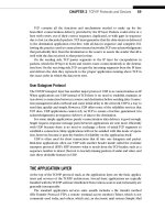
all implement a sort of “split” IP network layer. For example, if the Ethernet Type fi eld is
set to 0x0800 the packet is handed off to the IPv4 process, and if the Type fi eld is set to
0x86DD, then the packet is handed off to the IPv6 process. This is shown conceptually
in Figure 9.6.
The dual protocol stack must provide error messages that are IPv6 “aware,” and rout-
ing protocols have to adapt to IPv6 addresses as well (as we’ll see). And in spite of the
fi gure, which is a very common representation, the TCP/UDP layer is also dual.
Dual protocols stacks are not new with IPv6. This method was frequently used
whenever two or more protocol stacks had to share a single host interface. In fact, very
complex arrangements were not unknown, with IBM’s (and Microsoft’s) NetBios shar-
ing the network with Novell’s NetWare and IP itself (for Internet access).
Tunneling
Tunneling is a much misunderstood topic in general. This section talks about IPv6 tun-
nels, but networks also feature IPSec tunnels, VPN tunnels, and possibly even more. But
they all employ tunnels. Tunneling occurs whenever the normal sequence of encap-
sulation headers is violated. That’s all.
Application Services
TCP/UDP
IPv4 IPv6
Network Access (Ethernet, etc.)
Physical Network
FIGURE 9.6
Dual protocol stacks for IPv4 and IPv6 sharing a single network connection. Technically, TCP and
UDP have to be adjusted for an IPv6 environment.
252 PART II Core Protocols
Normally, a message is broken up into segments, which are put inside packets placed
inside frames that are sent as a sequence of bits to an adjacent system. The receiver
usually expects that the frame contains a packet, and so on, but what if it doesn’t? Then
the device is using tunneling.
We’ve already seen a form of tunneling in action. When we put PPP frames inside
Ethernet frames, we put a frame inside a frame and violated the normal OSI-RM
sequence of headers. That’s okay, as long as the receiver knows the sequence of head-
ers the sender is generating.
Not all devices need to know the exact sequence of encapsulations used by the
sender and receiver. Only the endpoints (usually hosts, but not always) need to know
how to encapsulate the data at one end and process the headers correctly at the des-
tination. In between, inside the tunnel, all other devices can treat the data units as
usual.
Tunneling in a mixed IPv4 and IPv6 network is used to transport IPv6 packets over
a series of IPv4 routers or to an IPv4 host. There is a lot of variation in tunnels to sup-
port IPv4/IPv6 operation. For example, a native IPv6 backbone might tunnel IPv4 to
reduce address consumption in the network core. For the sake of simplicity, let’s con-
sider four types of tunnels and two major scenarios for their use:
1. Host to router—Hosts with dual-stack capabilities can tunnel IPv6 packets to a
dual-stack router that is only reachable over a series IPv4-only device.
2. Router to router—Routers with dual-stack capabilities can tunnel IPv6 packets
over an IPv4 infrastructure to other routers.
3. Router to host—Routers with dual-stack capabilities can tunnel IPv6 packets
over an IPv4 infrastructure to a dual-stack destination host.
4. Host to host—Hosts with dual-stack capabilities can tunnel IPv6 packets over an
IPv4 infrastructure to other dual-stack IP hosts without an intervening router.
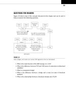
The four types of tunnels are shown in Figure 9.7. When the IPv6 packet is sent to
a router (the fi rst two tunneling methods), the endpoint of the tunnel is not the same
as the destination, so the destination address of the IPv6 packet does not indicate the
same device as the IPv4 tunnel endpoint address that carries the IPv6 packet. The
source host or router must have the tunnel endpoint’s IPv4 address confi gured. This is
called confi gured tunneling.
In contrast, the last two methods send the encapsulated IPv6 packet directly to the
destination host, so the IPv4 and IPv6 addresses used correspond to the same host. This
lets the IPv6 destinations use IPv4-compatible addresses that are derived automatically
by the devices. This is called automatic tunneling because it does not require explicit
confi guration.
Automatic tunneling uses a special form of the IPv6 address. The 32-bit IPv4 address
is simply prepended with 96 zero bits in the form
0:0:0:0:0:0:<IPv4 address>. This
format is abbreviated as ::<IPv4 address>.
All dual-stack IP hosts recognize this format and encapsulate the IPv6 packet inside
an IPv4 packet using the embedded IPv4 address, creating an end-to-end tunnel. The
CHAPTER 9 Forwarding IP Packets 253
receiver simply strips off the IPv4 header and processes the IPv6 header and packet
inside.
Hosts that only run IPv6 can use dual-stack routers to communicate using this spe-
cial form of IPv6 address also. Dual-stack routers recognize the IPv6 traffi c and use the
last 32 bits to create the IPv4 address for the IPv4 “wrapper.” Figure 9.8 shows how this
special addressing format works. Naturally, this requires IPv6-only hosts to have valid
and routable IPv4 addresses, which clearly marks the format as a transitional method.
If the IPv6 address is not in this special address form, then a confi gured tunnel must
be used, or, if every device on the path from source to destination uses dual protocol
stacks, or IPv6 only, well-formed IPv6 addresses can be used.
IPv4/IPv6
Host
Host to Router
Router to Router
(intermediate
hops)
Router to Host
(last hop)
Host to Host
IPv4 Network
(IPv4 routers)
IPv4 Network
(IPv4 routers)
IPv4 Network
(IPv4 routers)
IPv4 Network
(IPv4 routers)
IPv4/IPv6
Host
IPv4/IPv6
Host
IPv4/IPv6
Router
IPv6-only
Router
IPv4/IPv6
Router
IPv4-only
Router
IPv4/IPv6
Host
FIGURE 9.7
The various types of IPv6 tunnels, showing host and router situations that can be used to connect.
IPv4 Header IPv6 Header
IPv6 Header
IPv4
Dest.
Addr.:
192.168.38.156
TCP/UDP Header
TCP/UDP Header
Data
Data
IPv6 Destination Address:
0:0:0:0:0:0:192.168.38.156
(::192.168.38.156)
FIGURE 9.8
The special IPv6 tunnel-addressing format for dual-stack routers.
254 PART II Core Protocols
TUNNELING MECHANISMS
The theory of tunneling IPv6 packets through a collection of IPv4 routers is one thing.
Exactly how to do it is another. There are several tunnel mechanisms that embody the
concepts discussed previously.
Manually configured tunnels—These are defined in RFC 2893, and both end-
points of the tunnel must have both IPv4 and IPv6 addresses. These tunnels are
usually used between dual-stack edge routers.
Generic Routing Encapsulation (GRE) tunnels—GRE tunnels were designed to
transport non-IP protocols over an IP network. But GRE is also a good way to
carry IPv6 across the IPv4 routers. We used a GRE tunnel earlier in this chapter.
IPv4-compatible (6over4) tunnels—Also defined in RFC 2893, these are the
automatic tunnels based on IPv4-compatible IPv6 addresses using the ::<IPv4
address> form of IPv6 address.
6to4 tunnels—Another form of automatic tunnel defined in RFC 3065. They use an
IPv4 address embedded in the IPv6 address to identify the tunnel endpoint.
Intra-site Automatic Tunnel Addressing Protocol (ISATAP) tunnels—ISATAP tun-
nels are a mechanism much like 6to4 tunneling, but for local site (campus)
networks. An ISATAP address uses a special prefix and the IPv4 address to
identify the endpoint.
The differences between the 6to4 tunnel and the ISATAP tunnel address are shown
in Figure 9.9.
128 bits
16 bits 32 bits
32 bits64 bits
Subnet Prefix 0005EFE IPv4 Address
32 bits
16 bits 64 bits
Interface IDSubnet ID
(a)
(b)
001000000000000010
2002:
IPv4 Address
FIGURE 9.9
The differences between 6to4 and ISATAP tunnel addressing, showing how the 128 bits of the
IPv6 address are structured in each case. (a) 6to4 tunneling address format (b) ISATAP tunneling
address format
CHAPTER 9 Forwarding IP Packets 255
TRANSITION CONSIDERATIONS
Routers occupy a key position during the transition period between IPv4 and
IPv6. There are still a lot of routers, mostly older ones, that do not handle IPv6 or
understand only the ::<IPv4 address> form of IPv6 address. How will IPv4 and IPv6
routers and hosts interoperate?
A transition plan has been put in place and contains some distinct terminology that
is new. The IPv4 to IPv6 transition plan defi nes the following terms for nodes:
■ IPv4-only Node—A host or router that implements only IPv4.
■ IPv6/IPv4 (dual) Node—A host or router that implements both
IPv4 and IPv6.
■ IPv6-only Node—A host or router that implements only IPv6.
■ IPv6 Node—A host or router that implements IPv6. Both IPv4/IPv6 dual
nodes and IPv6-only nodes are included in this category.
■ IPv4 Node—A host or router that implements IPv4. Both IPv4/IPv6 dual
nodes and IPv4-only nodes are included in this category.
In addition, the plan defi nes three types of addresses:
1. IPv4-compatible IPv6 address—An address assigned to an IPv6 node that can
be used in both IPv6 and IPv4 packets. The ::<IPv4 address> format is used for
this type of IP address. For example, an address such as ::10.10.11.66 is used
when there is no IPv6 router available.
2. IPv4-mapped IPv6 address—An address assigned to an IPv4-only node rep-
resented as an IPv6 address. These addresses always identify IPv4-only nodes,
never IPv4/IPv6 or IPv6-only nodes. These are provided when an IPv6 applica-
tion requests the host name for a node with an IPv4 address only. For example,
::FFFF:10.10.12.166 is an IPv4-mapped IPv6 address.
3. IPv6-only address—An address globally assigned to any IPv4/IPv6 or IPv6-only
node. These addresses never identify IPv4-only nodes.
These terms can be somewhat confusing, but all they mean is that hosts and routers
can be classifi ed either as IPv4 devices, IPv6 devices, or both IPv4 and IPv6 devices.
The IPv4/IPv6 devices are capable of understanding and using both IPv4 and IPv6.
However, the IPv6-only address (an address that has no relationship to an IPv4 address)
can be used in an IPv6/IPv4 device.
256 PART II Core Protocols
QUESTIONS FOR READERS
Figure 9.10 shows some of the concepts discussed in this chapter and can be used to
help you answer the following questions.
1. Which router, based on the architecture in the fi gure, is probably a small site
router? Which is probably a large Internet backbone router?
2. Which output interface, based on the routing table shown in the fi gure, will
packets arriving from the directly attached host for IPv4 address
10.10.11.1 use
for forwarding? Assume longest match is used.
3. Which output interface will packets for 10.10.192.10 use? Assume the longest
match is used.
4. Which IPv6 tunneling protocol can be used between the two hosts? How many
bits will be used for the subnet identifi er?
5. Do the routers require IPv6 support to deliver packets between the two hosts?
Router with
NVRAM
and DRAM
Interface 1
Interface 2
Interface 3
Router
with RE
and PFE
Host
Supporting
6to4 and
ISATAP
Tunnels
Host
Supporting
6to4
Tunnels
admin@router0> show route
inet.0: 2 destinations, 2 routes (2 active
10.10.0.0/16 >via interface #1
10.10.64.0/18 >via interface #2
10.10.128.0/18 >via interface #3
FIGURE 9.10
A simple network of routers and hosts, showing architecture, a routing table, and tunnel support.
257