The Illustrated Network- P32 pdf
Bạn đang xem bản rút gọn của tài liệu. Xem và tải ngay bản đầy đủ của tài liệu tại đây (242.85 KB, 10 trang )
CHAPTER
What You Will Learn
In this chapter, you will learn about the TCP transport layer protocol, which is
the connection-oriented, more reliable companion of UDP. We’ll talk about all
the fi elds in the TCP header (which are many) and how TCP’s distinctive three-way
handshake works.
You will learn how TCP operates during the data transfer and disconnect phase,
as well as some of the options that have been established to extend TCP’s use for
today’s networking conditions.
Transmission Control
Protocol
11
The Transmission Control Protocol (TCP) is as complex as UDP is simple. Some of the
same concepts apply to both because both TCP and UDP are end-to-end protocols.
Sockets and ports, well-known, dynamic, and private, apply to both. TCP is IP protocol
6, but the ports are usually the same as UDP and run from 0 to 65,535. The major dif-
ference between UDP and TCP is that TCP is connection oriented. And that makes all
the difference.
Internet specifi cations variously refer to connections as “virtual circuits,” “fl ows,”
or “packet-switched services,” depending on the context. These subtle variations are
unnecessary for this book, and we simply use the term “connection.” A connection is
a logical relationship between two endpoints (hosts) on a network. Connections can
be permanent (although the proper term is “semipermanent”) or on demand (often
called “switched”). Permanent connections are usually set up by manual confi guration
of the network nodes. (On the Internet, this equates to a series of very specifi c static
routes.) On-demand connections require some type of signaling protocol to estab-
lish connections on the fl y, node by node through the network from the source (the
“caller”) host to the destination (the “callee”) host.
Permanent connections are like intercoms: You can talk right away or at any time
and know the other end is there. However, you can only talk to that specifi c endpoint
on that connection. On-demand connections are like telephone calls: You have to wait
until the other end “answers” before you talk or send any information, but you connect
to (call) anyone in the world.
CE0
lo0: 192.168.0.1
fe-1/3/0: 10.10.11.1
MAC: 00:05:85:88:cc:db
(Juniper_88:cc:db)
IPv6: fe80:205:85ff:fe88:ccdb
P9
lo0: 192.168.9.1
PE5
lo0: 192.168.5.1
P4
lo0: 192.168.4.1
so-0/0/1
79.2
so-0/0/1
24.2
so-0/0/0
47.1
so-0/0/2
29.2
so-0/0/3
49.2
so-0/0/3
49.1
so-0/0/0
59.2
so-0/0/2
45.1
so-0/0/2
45.2
so-0/0/0
59.1
ge-0/0/3
50.2
ge-0/0/3
50.1
DSL Link
Ethernet LAN Switch with Twisted-Pair Wiring
bsdclient lnxserver wincli1
em0: 10.10.11.177
MAC: 00:0e:0c:3b:8f:94
(Intel_3b:8f:94)
IPv6: fe80::20e:
cff:fe3b:8f94
eth0: 10.10.11.66
MAC: 00:d0:b7:1f:fe:e6
(Intel_1f:fe:e6)
IPv6: fe80::2d0:
b7ff:fe1f:fee6
LAN2: 10.10.11.51
MAC: 00:0e:0c:3b:88:3c
(Intel_3b:88:3c)
IPv6: fe80::20e:
cff:fe3b:883c
LAN2: 10.10.11.111
MAC: 00:0e:0c:3b:87:36
(Intel_3b:87:36)
IPv6: fe80::20e:
cff:fe3b:8736
winsvr1
LAN1
Los Angeles
Office
Ace ISP
AS 65459
Wireless
in Home
Solid rules ϭ SONET/SDH
Dashed rules ϭ Gig Ethernet
Note: All links use 10.0.x.y
addressing only the last
two octets are shown.
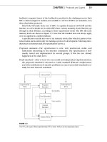
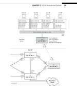
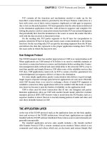
FIGURE 11.1
TCP client–server connections, showing that this chapter uses a client and server pair on the
same LAN.
280 PART II Core Protocols
CE6
lo0: 192.168.6.1
fe-1/3/0: 10.10.12.1
MAC: 0:05:85:8b:bc:db
(Juniper_8b:bc:db)
IPv6: fe80:205:85ff:fe8b:bcdb
Ethernet LAN Switch with Twisted-Pair Wiring
bsdserver lnxclient winsvr2 wincli2
eth0: 10.10.12.77
MAC: 00:0e:0c:3b:87:32
(Intel_3b:87:32)
IPv6: fe80::20e:
cff:fe3b:8732
eth0: 10.10.12.166
MAC: 00:b0:d0:45:34:64
(Dell_45:34:64)
IPv6: fe80::2b0:
d0ff:fe45:3464
LAN2: 10.10.12.52
MAC: 00:0e:0c:3b:88:56
(Intel_3b:88:56)
IPv6: fe80::20e:
cff:fe3b:8856
LAN2: 10.10.12.222
MAC: 00:02:b3:27:fa:8c
IPv6: fe80::202:
b3ff:fe27:fa8c
LAN2
New York
Office
P7
lo0: 192.168.7.1
PE1
lo0: 192.168.1.1
P2
lo0: 192.168.2.1
so-0/0/1
79.1
so-0/0/1
24.1
so-0/0/0
47.2
so-0/0/2
29.1
so-0/0/3
27.2
so-0/0/3
27.1
so-0/0/2
17.2
so-0/0/2
17.1
so-0/0/0
12.2
so-0/0/0
12.1
ge-0/0/3
16.2
ge-0/0/3
16.1
Best ISP
AS 65127
Global Public
Internet
CHAPTER 11 Transmission Control Protocol 281
TCP AND CONNECTIONS
As much as router discussions become talks about IP packets and headers, host discus-
sions tend to become talks about TCP. However, a lot of the demonstrations involving
TCP revolve around things that can go wrong. What happens if an acknowledgment
(ACK) is lost? What happens when two hosts send almost simultaneous connection
requests (SYN) to open a connection? With the emphasis on corner cases, many pages
written on TCP become exercises in exceptions. Yet there is much to be learned about
TCP just by watching it work in a normal, error-free environment.
Instead of watching to check whether TCP recovers from lost segments (it does),
we’ll just capture the sequence of TCP segments used on various combinations of
the three operating system platforms and see what’s going on. Later, we’ll use an FTP
data transfer between wincli2 and bsdserver (both on LAN2) to look at TCP in action.
In many ways it is an odd protocol, but we’ll only look at the basics and examine FTP
in detail in a later chapter. Figure 11.1 shows these hosts on the network.
As before, we’ll use Ethereal to look at frames and packets. There is also a utility
called tcpdump, which is bundled with almost every TCP/IP implementation. The major
exception, as might be expected, is Windows. The Windows version, windump, is not
much different than our familiar Ethereal, so we’ll just use Ethereal to capture our Win-
dows TCP sessions. Because TCP operation is complicated, let’s look at some details of
TCP operation before looking at how TCP looks on the Illustrated Network.
THE TCP HEADER
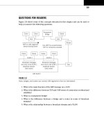
The TCP header is the same for IPv4 and IPv6 and is shown in Figure 11.2. We’ve
already talked about the port fi elds in the previous chapter on UDP. Only the features
unique to TCP are described in detail.
Source and destination port—In some Unix implementations, source port num-
bers between 1024 and 4999 are called ephemeral ports. If an application
does not specify a source port to use, the operating systems will use a source
port number in this range. This range can be expanded and changed (but not
always), and 49,152 through 65,535 is more in line with current standards. Use
of ephemeral ports impacts firewall use and limits the number of connections
a host can have open at any one time.
Sequence number—Each new connection (re-tries of failed connections do not
count) uses a different initial sequence number (ISN) as the basis for tracking
segments. Windows uses a very simple time-based formula to compute that
ISN, while Unix ISNs are more elaborate (ISNs can be spoofed by hackers).
Acknowledgment number—This number must be greater than or equal to zero
(even a TCP SYN consumes one sequence number) except for the all 1’s ISN.
All segments on an established connection must have this bit set. If there is no
282 PART II Core Protocols
actual data in the received segment, the acknowledgment number increments
by 1. (Every byte in TCP is still counted, but that’s not all that contributes to
the sequence number field.)
Header length—The TCP header length in 4-byte units.
Reserved—Four bits are reserved for future use.
ECN flags—The two explicit congestion notification (ECN) bits are used to tell
the host when the network is experiencing congestion and send windows
should be adjusted.
URG, ACK, PSH, RST, SYN, FIN—These six single-bit fields (Urgent, Acknowledg-
ment, Push, Reset, Sync, and Final) give the receiver more information on how
to process the TCP segment. Table 11.1 shows their functions.
Window size—The size of receive window that the destination host has set. This
field is used in TCP flow control and congestion control. It should not be set
to zero in an initial SYN segment.
Checksum—An error-checking field on the entire TCP segment and header as
well as some fields from the IP datagram (the pseudo-header). The fields are
1 byte
32 bits
H
e
a
d
e
r
1 byte
Source Port
Sequence Number
Acknowledgment Number
Window SizeRESV
E
C
N
E
C
N
U
R
G
A
C
K
P
S
H
R
S
T
S
Y
N
F
I
N
Header
Length
TCP Checksum
DATA (application message)
Options Field (variable length, maximum 40 bytes, 0 padded to 4-byte multiple)
Urgent Pointer
Destination Port
1 byte 1 byte
FIGURE 11.2
The TCP header fi elds. Note that some fi elds are a single bit wide, and others, like the options
fi eld, can be up to 40 bytes (320 bits) long.
CHAPTER 11 Transmission Control Protocol 283
the same as in UDP. If the checksum computed does not match the received
value, the segment is silently discarded.
Urgent pointer—If the URG control bit is set, the start of the TCP segment con-
tains important data that the source has placed before the “normal” contents
of the segment data field. Usually, this is a short piece of data (such as CTRL-C).
This field points to the first nonurgent data byte.
Options and padding—TCP options are padded to a 4-byte boundary and can be
a maximum of 40 bytes long. Generally, a 1-byte Type is followed by a 1-byte
Length field (including these initial 2 bytes), and then the actual options. The
options are listed in Table 11.2.
Table 11.1 TCP Control Bits by Abbreviation and Function
Bit Function
URG If set, the Urgent Pointer fi eld value is valid (often resulting from an interrupt-like
CTRL-C). Seldom used, but intended to raise the priority of the segment.
ACK If set, the Acknowledgment Number fi eld is valid.
PSH If set, the receiver should not buffer the segment data, but pass them directly to the
application. Interactive applications use this, but few others.
RST If set, the connection should be aborted. A favorite target of hackers “hijacking” TCP
connections, a series of rules now govern proper reactions to this bit.
SYN If set, the hosts should synchronize sequence numbers and establish a connection.
FIN If set, the sender had fi nished sending data and initiated a close of the connection.
Table 11.2 TCP Option Types, Showing Abbreviation (Meaning), Length, and RFC
in Which Established
Type Meaning Total Length and Description RFC
0 EOL 1 byte, indicates end of option list (only used if end of
options is not end of header)
793
1 NOP 1 byte, no option (used as padding to align header with
Header-Length Field)
793
2 MSS 4 bytes, the last 2 of which indicate the maximum payload
that one host will try to send another. Can only appear in
SYN and does not change.
793
879
284 PART II Core Protocols
TCP MECHANISMS
It might not be obvious why TCP connections should be such a complication. One of
the reasons is that TCP adds more to connectionless IP than connection capability. The
TCP service also provides aspects of what the ISO-RM defi nes as Session Layer services,
services that include the history (a popular term is “state variables”) of the connection
progress. Connections also provide a convenient structure with which to associate
QoS parameters, although every layer of any protocol stack always has some QoS duties
to perform, even if it is only error checking.
Offi cially, TCP is a virtual circuit service that adds reliability to the IP layer, reli-
ability that is lacking in UDP. TCP also provides sequencing and fl ow control to the
host-to-host interaction, which in turn provides a congestion control mechanism to the
routing network as a whole (as long as TCP, normally an end-to-end concern, is aware
of the congested condition). The fl ow control mechanism in TCP is a sliding window
procedure that prevents senders from overwhelming receivers and applies in both
directions of a TCP connection.
TCP was initially defi ned in RFC 793, refi ned in RFCs 879, 1106, 1110, and 1323
(which obsoleted RFC 1072 and RFC 1185). RFCs 1644 and 1693 extended TCP to
support transactions, which can be loosely understood as “connection-oriented
Table 11.2 (continued)
Type Meaning Total Length and Description RFC
3 WSCALE 3 bytes, the last establishing a multiplicative (scaling) factor.
Supports bit-shifted window values above 65,535.
1072
4 SACKOK 2 bytes, indicating that selective ACKs are permitted. 2018
5 SACK Of variable length, these are the selective ACKs. 1072
6 Echo 6 bytes, the last 4 of which are to be echoed. 1072
7 Echo reply 6 bytes, the last 4 of which echo the above. 1072
8 Timestamp 10 bytes, the last 8 of which are used to compute the retrans-
mission timer through the RTT calculation. Makes sure that an
old sequence number is not accepted by the current connection.
1323
9 POC perm 2 bytes, indicating that the partial order service is permitted. 1693
10 POC profi le 3 bytes, the last carrying 2-bit fl ags. 1693
11 CC 6 bytes, the last 4 providing a segment connection count. 1644
12 CCNEW 6 bytes, the last 4 providing new connection count. 1644
13 CCECHO
6 bytes, the last 4 echoing previous connection count.
1644
CHAPTER 11 Transmission Control Protocol 285
request–response pairs that cannot use UDP.” RFC 3168 added explicit congestion noti-
fi cation (ECN) bits to the TCP header. These bits were “added” by redefi ning bits 6 and
7 in the TOS fi eld of the packet header.
TCP and Transactions
It is important to note that TCP does not use the term “transaction” to describe
those peculiar interactions that require coordinated actions among multiple hosts
on the network. A familiar “transaction” is an accounting process that is not com-
plete until both one account has been debited and another has been credited.
Database transactions are a completely different notion than what a transaction
means in TCP.
But this is not the purpose of transactions for TCP (T/TCP)! TCP “transactions”
are a way to sneak a quick burst of request–response data into an exchange of con-
nection setup segments, similar to the way that UDP works.
TCP headers can be between 20 bytes (typical) and 60 bytes long when options are
used (not often). A segment, which is the content of a TCP data unit, is essentially a por-
tion of the application’s send buffer. As bytes accumulate in the send buffer, they will
exceed the maximum segment size (MSS) established for the connection. These bytes
receive a TCP header and are sent inside an IP packet. There are also ways to “push” a
partially full send buffer onto the network.
At the receiver, the segment is added to a receive buffer until complete or until the
application has enough data to process. Naturally, the amount of data exchanged varies
greatly.
Let’s look at how TCP works and then examine the header fi elds that make it all
happen. It might seem strange to talk about major TCP features before the TCP header
has been presented, but the operation of many of the fi elds in the TCP header depend
on terminology and concepts used during TCP connection and other procedures.
CONNECTIONS AND THE THREE-WAY HANDSHAKE
TCP establishes end-to-end connections over the unreliable, best-effort IP packet ser-
vice using a special sequence of three TCP segments sent from client to server and
back called a three-way handshake. Why three ways? Because packets containing the
TCP segment that ask a server to accept another connection and the server’s response
might be lost on the IP router network, leaving the hosts unsure of exactly what is
going on.
Once the three segments are exchanged, data transfer can take place from host
to host in either direction. Connections can be dropped by either host with a simple
286 PART II Core Protocols
exchange of segments (four in total), although the other host can delay the dropping
until fi nal data are sent, a feature rarely used.
TCP uses unique terminology for the connection process. A single bit called the
SYN (synchronization) bit is used to indicate a connection request. This single bit is
still embedded in a complete 20-byte (usually) TCP header, and other information, such
as the initial sequence number (ISN) used to track segments, is sent to the other host.
Connections and data segments are acknowledged with the ACK bit, and a request to
terminate a connection is made with the FIN (fi nal) bit.
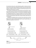
The entire TCP connection procedure, from three-way handshake to data transfer
to disconnect, is shown in Figure 11.3. TCP also allows for the case where two hosts
performs an active open at the same time, but this is unlikely.
This example shows a small fi le transfer to a server (with the server sending 1000
bytes back to the client) using 1000-byte segments, but only to make the sequence
numbers and acknowledgments easier to follow. The whole fi le is smaller than the
CLIENT
Active OPEN
SERVER
Passive OPEN
Client–Server File Transfer Using
1000-byte Segments
OPEN
3-way Handshake
Complete
(sends 1000
bytes back)
(3000 bytes of
window full)
CLOSING
WAIT!
OPEN
Data Transfer
SEQ and ACK
SEQ (ISN) 2000 WIN 5840
SYN SEQ (ISN) 4000 WIN 8760
SEQ 2001 WIN 5840
MSS (OPT)1460
MSS (OPT)1460
SEQ 2001 ACK 4001
SEQ 4001 ACK 3001
ACK 4001SEQ 3001
ACK 4001SEQ 4001
ACK 4001SEQ 5001
ACK 6001(no data)
(Transfer
continues )
Connection
Release
CLOSING
FIN SEQ 4001 ACK 10001
ACK SEQ 10001 ACK 4002
FIN SEQ 10001 ACK 4002
ACK SEQ 4002 ACK 10002
ACK
SYN
ACK 4001
WAIT!
.
.
FIGURE 11.3
Client–server interaction with TCP, showing the three connection phases of setup, data transfer,
and release (disconnect).
CHAPTER 11 Transmission Control Protocol 287
server host’s receive window and nothing goes wrong (but things often go wrong in
the real world).
Note that to send even one exchange of a request–response pair inside segments,
TCP has to generate seven additional packets. This is a lot of packet overhead, and the
whole process is just slow over high latency (delay) links. This is one reason that UDP
is becoming more popular as networks themselves become more reliable.
Connection Establishment
Let’s look at the normal TCP connection establishment’s three-way handshake in some
detail. The three messages establish three important pieces of information that both
sides of the connection need to know.
1. The ISNs to use for outgoing data (in order to deter hackers, these should not
be predictable).
2. The buffer space (window) available locally for data, in bytes.
3. The Maximum Segment Size (MSS) is a TCP Option and sets the largest segment
that the local host will accept. The MSS is usually the link MTU size minus the 40
bytes of the TCP and IP headers, but many implementations use segments of 512
or 536 bytes (it’s a maximum, not a demand).
A server issues a passive open and waits for a client’s active open SYN, which in
this case has an ISN of 2000, a window of 5840 bytes and an MSS of 1460 (common
because most hosts are on Ethernet LANs). The window is almost always a multiple
of the MSS (1460 3 4 5 5840 bytes). The server responds with a SYN and declares the
connection open, setting its own ISN to 4000, and “acknowledging” sequence number
2001 (it really means “the next byte I get from you in a segment should be numbered
2001”). The server also established a window of 8760 bytes and an MSS of 1460 (1460 3
6 5 8760 bytes).
Finally, the client declares the connection open and returns an ACK (a segment with
the ACK bit set in the header) with the sequence number expected (2001) and the
acknowledgment fi eld set to 4001 (which the server expects). TCP sequence numbers
count every byte on the data stream, and the 32-bit sequence fi eld allows more than
4 billion bytes to be outstanding (nevertheless, high-speed transports such as Gigabit
Ethernet roll this fi eld over too quickly for comfort, so special “scaling” mechanisms are
available for these link speeds).
TCP’s three-way handshake has two important functions. It makes sure that both
sides know that they are ready to transfer data and it also allows both sides to agree
on the initial sequence numbers, which are sent and acknowledged (so there is no
mistake about them) during the handshake. Why are the initial sequence numbers so
important? If the sequence numbers are not randomized and set properly, it is possible
for malicious users to hijack the TCP session (which can be reliable connections to a
bank, a store, or some other commercial entity).
288 PART II Core Protocols