The Illustrated Network- P33 pptx
Bạn đang xem bản rút gọn của tài liệu. Xem và tải ngay bản đầy đủ của tài liệu tại đây (322.31 KB, 10 trang )
Each device chooses a random initial sequence number to begin counting every
byte in the stream sent. How can the two devices agree on both sequence number val-
ues in about only three messages? Each segment contains a separate sequence number
fi eld and acknowledgment fi eld. In Figure 11.3, the client chooses an initial sequence
number (ISN) in the fi rst SYN sent to the server. The server ACKs the ISN by adding one
to the proposed ISN (ACKs always inform the sender of the next byte expected) and
sending it in the SYN sent to the client to propose its own ISN. The client’s ISN could
be rejected, if, for example, the number is the same as used for the previous connection,
but that is not considered here. Usually, the ACK from the client both acknowledges the
ISN from the server (with server’s ISN 1 1 in the acknowledgment fi eld) and the con-
nection is established with both sides agreeing on ISN. Note that no information is sent
in the three-way handshake; it should be held until the connection is established.
This three-way handshake is the universal mechanism for opening a TCP connec-
tion. Oddly, the RFC does not insist that connections begin this way, especially with
regard to setting other control bits in the TCP header (there are three others in addition
to SYN and ACK and FIN). Because TCP really expects some control bits to be used dur-
ing connection establishment and release, and others only during data transfer, hackers
can cause a lot of damage simply by messing around with wild combinations of the six
control bits, especially SYN/ACK/FIN, which asks for, uses, and releases a connection
all at the same time. For example, forging a SYN within the window of an existing SYN
would cause a reset. For this reason, developers have become more rigorous in their
interpretation of RFC 793.
Data Transfer
Sending data in the SYN segment is allowed in transaction TCP, but this is not typical.
Any data included are accepted, but are not processed until after the three-way hand-
shake completes. SYN data are used for round-trip time measurement (an important
part of TCP fl ow control) and network intrusion detection (NID) evasion and inser-
tion attacks (an important part of the hacker arsenal).
The simplest transfer scenario is one in which nothing goes wrong (which, fortu-
nately, happens a lot of the time). Figure 11.4 shows how the interplay between TCP
sequence numbers (which allow TCP to properly sequence segments that pop out of
the network in the wrong order) and acknowledgments allow both sides to detect
missing segments.
The client does not need to receive an ACK for each segment. As long as the estab-
lished receive window is not full, the sender can keep sending. A single ACK covers a
whole sequence of segments, as long as the ACK number is correct.
Ideally, an ACK for a full receive window’s worth of data will arrive at the sender
just as the window is fi lled, allowing the sender to continue to send at a steady rate.
This timing requires some knowledge of the round-trip time (RTT) to the partner host
and some adjustment of the segment-sending rate based on the RTT. Fortunately, both
of these mechanisms are available in TCP implementations.
CHAPTER 11 Transmission Control Protocol 289
What happens when a segment is “lost” on the underlying “best-effort” IP router net-
work? There are two possible scenarios, both of which are shown in Figure 11.4.
In the fi rst case, a 1000-byte data segment from the client to the server fails to arrive
at the server. Why? It could be that the network is congested, and packets are being
dropped by overstressed routers. Public data networks such as frame relay and ATM
(Asynchronous Transfer Mode) routinely discard their frames and cells under certain
conditions, leading to lost packets that form the payload of these data units.
If a segment is lost, the sender will not receive an ACK from the receiving host.
After a timeout period, which is adjusted periodically, the sender resends the last unac-
knowledged segment. The receiver then can send a single ACK for the entire sequence,
covering received segments beyond the missing one.
But what if the network is not congested and the lost packet resulted from a sim-
ple intermittent failure of a link between two routers? Today, most network errors are
caused by faulty connectors that exhibit specifi c intermittent failure patterns that
steadily worsen until they become permanent. Until then, the symptom is sporadic lost
packets on the link at random intervals. (Predictable intervals are the signature of some
outside agent at work.)
Client–Server Response to Lost Segments
CLIENT SERVER
ACK 3001SEQ 8001
ACK 3001SEQ 8001
ACK 3001SEQ 10001
ACK 3001SEQ 11001
ACK 10001(no data)
ACK 10001(no data)
ACK 14001(no data)
ACK 10001(no data)
ACK 10001(no data)
ACK 3001SEQ 12001
ACK 3001SEQ 13001
ACK 3001SEQ 10001
ACK 3001SEQ 9001
(Where is 8001?)
LOST!
LOST!
(Where is 10001?
Repeat ACK for
100001)
(Ah! There it is )
(Ah! There it is )
(Sending data )
(Thanks!)
(Where’s my
ACK for 8001
and 9001?)
Timeout!
(resend)
(Sending data )
.
.
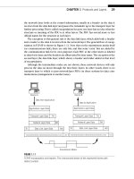
FIGURE 11.4
How TCP handles lost segments. The key here is that although the client might continue to send
data, the server will not acknowledge all of it until the missing segment shows up.
290 PART II Core Protocols
Waiting is just a waste of time if the network is not congested and the lost packet
was the result of a brief network “hiccup.” So TCP hosts are allowed to perform a “fast
recovery” with duplicate ACKs, which is also shown in Figure 11.4.
The server cannot ACK the received segments 11,001 and subsequent ones because
the missing segment 10,001 prevents it. (An ACK says that all data bytes up to the ACK
have been received.) So every time a segment arrives beyond the lost segment, the
host only ACKs the missing segment. This basically tells the other host “I’m still waiting
for the missing 8001 segment.” After several of these are received (the usual number
is three), the other host fi gures out that the missing segment is lost and not merely
delayed and resends the missing segment. The host (the server in this case) will then
ACK all of the received data.
The sender will still slow down the segment sending rate temporarily, but only in
case the missing segment was the result of network congestion.
Closing the Connection
Either side can close the TCP connection, but it’s common for the server to decide just
when to stop. The server usually knows when the fi le transfer is complete, or when the
user has typed logout and takes it from there. Unless the client still has more data to
send (not a rare occurrence with applications using persistent connections), the hosts
exchange four more segments to release the connection.
In the example, the server sends a segment with the FIN (fi nal) bit set, a sequence
number (whatever the incremented value should be), and acknowledges the last data
received at the server. The client responds with an ACK of the FIN and appropriate
sequence and acknowledgment numbers (no data were sent, so the sequence number
does not increment).
The TCP releases the connection and sends its own FIN to the server with the
same sequence and acknowledgment numbers. The server sends an ACK to the FIN
and increments the acknowledgment fi eld but not the sequence number. The connec-
tion is down.
But not really. The “best-effort” nature of the IP network means that delayed dupli-
cated could pop out of a router at any time and show up at either host. Routers don’t
do this just to be nasty, of course. Typically, a router that hangs or has a failed link rights
itself and fi nds packets in a buffer (which is just memory) and, trying to be helpful,
sends them out. Sometimes routing loops cause the same problem.
In any case, late duplicates must be detected and disposed of (which is one reason
the ISN space is 32 bits—about 4 billion—wide). The time to wait is supposed to be
twice as long as it could take a packet to have its TTL go to zero, but in practice this is
set to 4 minutes (making the packet transit time of the Internet 2 minutes, an incred-
ibly high value today, even for Cisco routers, which are fond of sending packets with
the TTL set to 255).
The wait time can be as high as 30 minutes, depending on TCP/IP implementation,
and resets itself if a delayed FIN pops out of the network. Because a server cannot
accept other connections from this client until the wait timer has expired, this often
led to “server paralysis” at early Web sites.
CHAPTER 11 Transmission Control Protocol 291
Today, many TCP implementations use an abrupt close to escape the wait-time
requirement. The server usually sends a FIN to the client, which fi rst ACKs and then
sends a RST (reset) segment to the server to release the connection immediately and
bypass the wait-time state.
FLOW CONTROL
Flow control prevents a sender from overwhelming a receiver with more data than it
can handle. With TCP, which resends all lost data, a receiver that is discarding data that
overfl ows the receive buffers is just digging itself a deeper and deeper hole.
Flow control can be performed by either the sender or the receiver. It sounds
strange to have senders performing fl ow control (how could they know when receiv-
ers are overwhelmed?), but that was the fi rst form of fl ow control used in older
networks.
Many early network devices were printers (actually, teletype machines, but the
point is the same). They had a hard enough job running network protocols and print-
ing the received data, and could not be expected to handle fl ow control as well. So
the senders (usually mainframes or minicomputers with a lot of horsepower for the
day) knew exactly what kind of printer they were sending to and their buffer sizes. If
a printer had a two-page buffer (it really depended on byte counts), the sender would
know enough to fi re off two pages and then wait for an acknowledgment from the
printer before sending more. If the printer ran out of paper, the acknowledgment was
delayed for a long time, and the sender had to decide whether it was okay to continue
or not.
Once processors grew in power, fl ow control could be handled by the receiver, and
this became the accepted method. Senders could send as fast as they could, up to a
maximum window size. Then senders had to wait until they received an acknowledg-
ment from the receiver. How is that fl ow control? Well, the receiver could delay the
acknowledgments, forcing the sender to slow down, and usually could also force the
sender to shrink its window. (Receivers might be receiving from many senders and
might be overwhelmed by the aggregate.)
Flow control can be implemented at any protocol level or even every protocol layer.
In practice, fl ow control is most often a function of the transport layer (end to end). Of
course, the application feeding TCP with data should be aware of the situation and also
slow down, but basic TCP could not do this.
TCP is a “byte-sequencing protocol” in which every byte is numbered. Although
each segment must be acknowledged, one acknowledgment can apply to multiple seg-
ments, as we have seen. Senders can keep sending until the data in all unacknowledged
segments equals the window size of the receiver. Then the sender must stop until an
acknowledgment is received from the receiving host.
This does not sound like much of a fl ow control mechanism, but it is. A receiver is
allowed to change the size of the receive window during a connection. If the receiver
292 PART II Core Protocols
fi nds that it cannot process the received window’s data fast enough, it can establish
a new (smaller) window size that must be respected by the sender. The receiver can
even “close” the window by shrinking it to zero. Nothing more can be sent until the
receiver has sent a special “window update ACK” (it’s not ACKing new data, so it’s not
a real ACK) with the new available window size.
The window size should be set to the network bandwidth multiplied by the round-
trip time to the remote host, which can be established in several ways. For example, a
100-Mbps Ethernet with a 5-millisecond (ms) round-trip time (RTT) would establish
a 64,000-byte window on each host (100 Mbps 3 5 ms 5 0.5 Mbits 5 512 kbits 5
64 kbytes). When the window size is “tuned” to the RTT this way, the sender should
receive an ACK for a window full of segments just in time to optimize the sending
process.
“Network” bandwidths vary, as do round-trip times. The windows can always shrink
or grow (up to the socket buffer maximum), but what should their initial value be?
The initial values used by various operating systems vary greatly, from a low of 4096
(which is not a good fi t for Ethernet’s usual frame size) to a high of 65,535 bytes. Free-
BSD defaults to 17,520 bytes, Linux to 32,120, and Windows XP to anywhere between
17,000 and 18,000 depending on details.
In Windows XP, the
TCPWindowSize can be changed to any value less that 64,240.
Most Unix-based systems allow changes to be made to the /etc/sysctl.conf fi le. When
adjusting TCP transmit and receive windows, make sure that the buffer space is suffi -
cient to prevent hanging of the network portion on the OS. In FreeBSD, this means
that the value of nmbclusters and socket buffers must be greater than the maximum
window size. Most Linux-based systems autotune this based on memory settings.
TCP Windows
How do the windows work during a TCP connection? TCP forms its segments in mem-
ory sequentially, based on segment size, each needing only a set of headers to be added
for transmission inside a frame. A conceptual “window” (it’s all really done with point-
ers) overlays this set of data, and two moveable boundaries are established in this series
of segments to form three types of data. There are segments waiting to be transmitted,
segments sent and waiting for an acknowledgment, and segments that have been sent
and acknowledged (but have not been purged from the buffer).
As acknowledgments are received, the window “slides” along, which is why the
process is commonly called a “sliding window.”
Figure 11.5 shows how the sender’s sliding window is used for fl ow control. (There
is another at the receiver, of course.) Here the segments just have numbers, but each
integer represents a whole 512, 1460, or whatever size segment. In this example, seg-
ments 20 through 25 have been sent and acknowledged, 26 through 29 have been sent
but not acknowledged, and segments 30 through 35 are waiting to be sent. The send
buffer is therefore 15 segments wide, and new segments replace the oldest as the buf-
fer wraps.
CHAPTER 11 Transmission Control Protocol 293
Flow Control and Congestion Control
When fl ow control is used as a form of congestion control for the whole network, the
network nodes themselves are the “receivers” and try to limit the amount of data that
senders dump into the network.
But now there is a problem. How can routers tell the hosts using TCP (which is an
end-to-end protocol) that there is congestion on the network? Routers are not sup-
posed to play around with the TCP headers in transit packets (routers have enough to
do), but they are allowed to play around with IP headers (and often have to).
Routers know when a network is congested (they are the fi rst to know), so they can
easily fl ip some bits in the IPv4 and IPv6 headers of the packets they route. These bits
are in the TOS (IPv4) and Flow (IPv6) fi elds, and the hosts can read these bits and react
to them by adjusting windows when necessary.
RFC 3168 establishes support for these bits in the IP and TCP headers. However,
support for explicit congestion notifi cation in TCP and IP routers is not mandatory,
and rare to nonexistent in routers today. Congestion in routers is usually indicated by
dropped packets.
PERFORMANCE ALGORITHMS
By now, it should be apparent that TCP is not an easy protocol to explore and understand.
This complexity of TCP is easy enough to understand: Underlying network should be
fast and simple, IP transport should be fast and simple as well, but unless every applica-
tion builds in complex mechanisms to ensure smooth data fl ow across the network, the
complexity of networking must be added to TCP. This is just as well, as the data transfer
concern is end to end, and TCP is the host-to-host layer, the last bastion of the network
shielding the application from network operations.
Sliding Window
Data sent and
acknowledged
Data sent and waiting
for acknowledgment
Data to
be sent
Data to
be sent
(Each integer represents a segment of
hundreds or thousands of bytes)
2120 22 23 24 25 26 27 28 29 30 31 32 33 34 35
FIGURE 11.5
TCP sliding window.
294 PART II Core Protocols
To look at it another way, if physical networks and IP routers had to do all that the
TCP layer of the protocol stack does, the network would be overwhelmed. Routers
would be overwhelmed by the amount of state information that they would need to
carry, so we delegate carrying that state information to the hosts. Of course, applica-
tions are many, and each one shouldn’t have to do it all. So TCP does it. By the way,
this consistent evolution away from “dumb terminal on a smart network” like X.25 to
“smart host on a dumb network” like TCP/IP is characteristic of the biggest changes in
networking over the years.
This chapter has covered only the basics, and TCP has been enhanced over the
years with many algorithms to enhance the performance of TCP in particular and the
network in general. ECN is only one of them. Several others exist and will only be men-
tioned here and not investigated in depth.
Delayed ACK—TCP is allowed to wait before sending an ACK. This cuts down
on the number of “stand-alone” ACKs, and lets a host wait for outgoing data
to “piggyback” an acknowledgment onto. Most implementations use a 200-ms
wait time.
Slow Start—Regardless of the receive window, a host computes a second con-
gestion window that starts off at one segment. After each ACK, this window
doubles in size until it matches the number of segments in the “regular”
window. This prevents senders from swamping receivers with data at the start
of a connection (although it’s not really very slow at all).
Defeating Silly Window Syndrome Early—TCP implementations processed
receive buffer data slowly, but received segments with large chunks of data.
Receivers then shrunk the window as if this “chunk” were normal. So windows
often shrunk to next to nothing and remained here. Receivers can “lie” to pre-
vent this, and senders can implement the Nagle algorithm to prevent the send-
ing of small segments, even if PUSHed. (Applications that naturally generate
small segments, such as a remote login, can turn this off.)
Scaling for Large Delay-Bandwidth Network Links—The TCP window-scale
option can be used to count more than 4 billion or so bytes before the sequence
number field wraps. A timestamp option sent in the SYN message helps also.
Scaling is sometimes needed because the Window field in the TCP header is
16 bits long, so the maximum window size is normally 64 kbytes. Larger
windows are needed for large-delay times, high-bandwidth product links
(such as the “long fat pipes” of satellite links). The scaling uses 3 bytes: 1 for type
(scaling), 1 for length (number of bytes), and 2 for a shift value called S. The
shift value provides a binary scaling factor to be applied to the usual value
in the Window field. Scaling shifts the window field value S bits to the left to
determine the actual window size to use.
Adjusting Resend Timeouts Based on Measured RTT—How long should a sender
wait for an ACK before resending a segment? If the resend timeout is too short,
CHAPTER 11 Transmission Control Protocol 295
resends might clutter up a network slow in relaying ACKs because it is teeter-
ing on the edge of congestion. If it is too long, it limits throughput and slows
recovery. And a value just right for TCP connection over the local LAN might
be much too short for connections around the globe over the Internet. TCP
adjusts its value for changing network conditions and link speeds in a rational
fashion based on measured RTT, how fast the RTT has change in the past.
TCP AND FTP
First we’ll use a Windows FTP utility on wincli2 (10.10.12.222) to grab the 30,000-
byte fi le test.stuff from the server bsdserver (10.10.12.77) and capture the TCP
(and FTP) packets with Ethereal. Both hosts are on the same LAN segment, so the pro-
cess should be quick and error-free.
The session took a total of 91 packets, but most of those were for the FTP data
transfer itself. The Ethereal statistics of the sessions note that it took about 55 seconds
from fi rst packet to last (much of which was “operator think time”), making the average
about 1.6 packets per second. A total of 36,000 bytes were sent back and forth, which
sounds like a lot of overhead, but it was a small fi le. The throughput on the 100 Mbps
LAN2 was about 5,200 bits per second, showing why networks with humans at the
controls have to be working very hard to fi ll up even a modestly fast LAN.
We’ve seen the Ethereal screen enough to just look at the data in the screen shots.
And Ethereal lets us expand all packets and create a PDF out of the capture fi le. This in
turn makes it easy to cut-and-paste exactly what needs to be shown in a single fi gure
instead of many.
For example, let’s look at the TCP three-way handshake that begins the session in
Figure 11.6.
FIGURE 11.6
Capture of three-way handshake. Note that Ethereal sets the “relative” sequence number to zero
instead of presenting the actual ISN value.
296 PART II Core Protocols
The fi rst frame, from 10.10.12.222 to 10.10.12.77, is detailed in the fi gure. The
window size is 65,535, the MSS is 1460 bytes (as expected for Ethernet), and selective
acknowledgments (
SACK) are permitted. The server’s receive window size is 57,344
bytes. Figure 11.7 shows the relevant TCP header values from the capture for the initial
connection setup (which is the FTP control connection).
Ethereal shows “relative” sequence and acknowledgment numbers, and these always
start at 0. But the fi gure shows the last bits of the actual hexadecimal values, showing
how the acknowledgment increments the value in sequence and acknowledgment
number (the number increments from 0x E33A to 0x E33B), even though no data
have been sent.
Note that Windows XP uses 2790 as a dynamic port number, which is really in the
registered port range and technically should not be used for this purpose.
This example is actually a good study in what can happen when “cross-platform”
TCP sessions occur, which is often. Several segments have bad TCP checksums. Since
we are on the same LAN segment, and the frame and packet passed error checks cor-
rectly, this is probably a quirk of TCP pseudo-header computation and no bits were
changed on the network. There is no ICMP message because TCP is above the IP layer.
Note that the application just sort of shrugs and keeps right on going (which happens
not once, but several times during the transfer). Things like this “non–error error” hap-
pen all the time in the real world of networking.
At the end of the session, there are really two “connections” between wincli2 and
bsdserver. The FTP session rides on top of the TCP connection. Usually, the FTP session
is ended by typing BYE or QUIT on the client. But the graphical package lets the user
just click a disconnect button, and takes the TCP connection down without ending the
FTP session fi rst. The FTP server objects to this breach of protocol and the FTP server
process sends a message with the text, You could at least say goodbye, to the client.
(No one will see it, but presumably the server feels better.)
TCP sessions do not have to be complex. Some are extremely simple. For example,
the common TCP/IP “echo” utility can use UDP or TCP. With UDP, an echo is a simple
Checksum Bad!
(But 3-way handshake
complete anyway )
OPEN
Passive OPEN
bsdserverwincli2
Active OPEN
(Client port 2790)
OPEN
FTP Handshake Using 1460-byte Segments
SYN SEQ (ISN) 72d1 WIN 65535
ACK SEQ 72d2 WIN 65535
ACK e33b
SYN SEQ (ISN) e33a WIN 57344
MSS (OPT) 1460
MSS (OPT) 1460
FIGURE 11.7
FTP three-way handshake, showing how the ISNs are incremented and acknowledged.
CHAPTER 11 Transmission Control Protocol 297
exchange of two segments, the request and reply. In TCP, the exchange is a 10-packet
sequence.
This is shown in Figure 11.8, which captures the echo “TESTstring” from lnxclient
to lnxserver. It includes the initial ARP request and response to fi nd the server.
Why so many packets? Here’s what happens during the sequence.
Handshake (packets 3 to 5)—The utility uses dynamic port 33,146, meaning
Linux is probably up-to-date on port assignments. The connection has a win-
dow of 5840 bytes, much smaller than the FreeBSD and Windows XP window
sizes. The MMS is 1460, and the exchange has a rich set of TCP options, includ-
ing timestamps (TSV) and windows scaling (not used, and not shown in the
figure).
Transfer (packets 6 to 9)—Note that each ECHO message, request and response, is
acknowledged. Ethereal shows relative acknowledgment numbers, so ACK=11
means that 10 bytes are being ACKed (the actual number is 0x0A8DA551, o r
177,055,057 in decimal.
Disconnect (packets 10 to 12)—A typical three-way “sign-off” is used.
We’ll see later in the book that most of the common applications implemented on
the Internet use TCP for its sequencing and resending features.
FIGURE 11.8
Echo using TCP, showing all packets of the ARP, three-way handshake, data transfer, and
connection release phases.
298 PART II Core Protocols