The Illustrated Network- P34 pdf
Bạn đang xem bản rút gọn của tài liệu. Xem và tải ngay bản đầy đủ của tài liệu tại đây (322.85 KB, 10 trang )
QUESTIONS FOR READERS
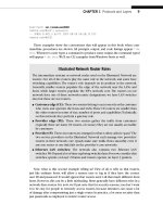
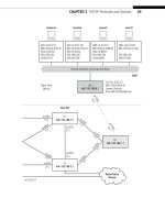
Figure 11.9 shows some of the concepts discussed in this chapter and can be used to
help you answer the following questions.
1. What are the three phases of connection-oriented communications?
2. Which fi elds are present in the TCP header but absent in UDP? Why are they not
needed in UDP?
3. What is the TCP fl ow control mechanism called?
4. What does it mean when the initial sequence and acknowledgment numbers are
“relative”?
5. What is the silly window syndrome? What is the Nagle algorithm?
1 byte
Source Port
1 byte 1 byte 1 byte
Destination Port
Sequence Number
Acknowledgment Number
Header
Length
RESV Control Bits Window Size
TCP Checksum
wincli2
Active OPEN
(Client port 2790)
Urgent Pointer
Options Field (variable length, maximum 40 bytes, 0 padded to 4-byte multiple)
DATA (application message)
H
e
a
d
e
r
FTP Handshake Using 1460-byte Segments bsdserver
Passive OPEN
OPEN
OPEN
SYN SEQ (ISN) e33a WIN 57344
MSS (OPT) 1460
ACK SEQ 72d2 WIN 65535
ACK e33b
SYN SEQ(ISN) 72d1 WIN 65535
MSS (OPT) 1460
3-Way Handshake
Complete
FIGURE 11.9
The TCP header fi elds and three-way handshake example.
299
What You Will Learn
In this chapter, you will learn about how multiplexing (and demultiplexing) and
sockets are used in TCP/IP. We’ll see how multiplexing allows many applications
can share a single TCP/IP stock process.
You will learn how layer and applications interact to make multiplexing and
the socket concept very helpful in networking. We’ll use a small utility program to
investigate sockets and illustrate the concepts in this chapter.
Multiplexing and Sockets
12
Now that we’ve looked at UDP and TCP in detail, this chapter explores two key
concepts that make understanding how UDP and TCP work much easier: multiplex-
ing and sockets. Technically, the term should be “multiplexing and demultiplexing,” but
because mixing things together makes little sense unless you can get them back again,
most people just say “multiplexing” and let it go at that.
Why is multiplexing necessary? Most TCP/IP hosts have only one TCP/IP stack pro-
cess running, meaning that every packet passing into or out of the host uses the same
software process. This is due to the fact that the hosts usually have only one network
connection, although there are exceptions. However, a host system typically runs many
(technically, if other systems can access them, the host system is a server). All these
applications share the single network interface through multiplexing.
LAYERS AND APPLICATIONS
Both the source and destination port numbers, each 16 bits long, are included as the
fi rst fi elds of the TCP or UDP segment header. Well-known ports use numbers between
0 and 1023, which are reserved expressly for this purpose. In many TCP/IP implemen-
tations, there is a process (usually inetd or xinetd, the “Internet daemon”) that listens
for all TCP/IP activity on an interface. This process then launches to FTP or other appli-
cation processes on request, using the well-known ports as appropriate.
CE0
lo0: 192.168.0.1
fe-1/3/0: 10.10.11.1
MAC: 00:05:85:88:cc:db
(Juniper_88:cc:db)
IPv6: fe80:205:85ff:fe88:ccdb
P9
lo0: 192.168.9.1
PE5
lo0: 192.168.5.1
P4
lo0: 192.168.4.1
so-0/0/1
79.2
so-0/0/1
24.2
so-0/0/0
47.1
so-0/0/2
29.2
so-0/0/3
49.2
so-0/0/3
49.1
so-0/0/0
59.2
so-0/0/2
45.1
so-0/0/2
45.2
so-0/0/0
59.1
ge-0/0/3
50.2
ge-0/0/3
50.1
DSL Link
Ethernet LAN Switch with Twisted-Pair Wiring
bsdclient lnxserver wincli1
em0: 10.10.11.177
MAC: 00:0e:0c:3b:8f:94
(Intel_3b:8f:94)
IPv6: fe80::20e:
cff:fe3b:8f94
eth0: 10.10.11.66
MAC: 00:d0:b7:1f:fe:e6
(Intel_1f:fe:e6)
IPv6: fe80::2d0:
b7ff:fe1f:fee6
LAN2: 10.10.11.51
MAC: 00:0e:0c:3b:88:3c
(Intel_3b:88:3c)
IPv6: fe80::20e:
cff:fe3b:883c
LAN2: 10.10.11.111
MAC: 00:0e:0c:3b:87:36
(Intel_3b:87:36)
IPv6: fe80::20e:
cff:fe3b:8736
winsvr1
LAN1
Los Angeles
Office
Ace ISP
AS 65459
Wireless
in Home
Solid rules
ϭ
SONET/SDH
Dashed rules
ϭ
Gig Ethernet
Note: All links use 10.0.x.y
addressing only the last
two octets are shown.
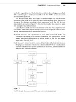
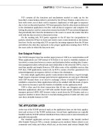
FIGURE 12.1
Sockets between Linux client and server, showing the devices used in this chapter to illustrate socket
operation.
302 PART II Core Protocols
CE6
lo0: 192.168.6.1
fe-1/3/0: 10.10.12.1
MAC: 0:05:85:8b:bc:db
(Juniper_8b:bc:db)
IPv6: fe80:205:85ff:fe8b:bcdb
Ethernet LAN Switch with Twisted-Pair Wiring
bsdserver lnxclient winsvr2 wincli2
eth0: 10.10.12.77
MAC: 00:0e:0c:3b:87:32
(Intel_3b:87:32)
IPv6: fe80::20e:
cff:fe3b:8732
eth0: 10.10.12.166
MAC: 00:b0:d0:45:34:64
(Dell_45:34:64)
IPv6: fe80::2b0:
d0ff:fe45:3464
LAN2: 10.10.12.52
MAC: 00:0e:0c:3b:88:56
(Intel_3b:88:56)
IPv6: fe80::20e:
cff:fe3b:8856
LAN2: 10.10.12.222
MAC: 00:02:b3:27:fa:8c
IPv6: fe80::202:
b3ff:fe27:fa8c
LAN2
New York
Office
P7
lo0: 192.168.7.1
PE1
lo0: 192.168.1.1
P2
lo0: 192.168.2.1
so-0/0/1
79.1
so-0/0/1
24.1
so-0/0/0
47.2
so-0/0/2
29.1
so-0/0/3
27.2
so-0/0/3
27.1
so-0/0/2
17.2
so-0/0/2
17.1
so-0/0/0
12.2
so-0/0/0
12.1
ge-0/0/3
16.2
ge-0/0/3
16.1
Best ISP
AS 65127
Global Public
Internet
CHAPTER 12 Multiplexing and Sockets 303
However, the well-known server port numbers can be statically mapped to their
respective application on the TCP/IP server, and that’s how we will explore them in
this introduction to sockets. With static mapping, the DNS (port number 53) or FTP
(port number 21) server processes (for example) must be running on the server at all
times in order for the server TCP protocol to accept connections to these application
form clients. Things are more complex when both IPv4 and IPv6 are running, but this
chapter considers the situation for IPv4 for simplicity.
This chapter will be a little different than the others. Instead of jumping right in and
capturing packets and then analyzing them, the socket packet capture is actually the
whole point of the chapter. So we’ll save that until last. In the meantime, we’ll develop
a socket-based application to work between the
lnxclient (10.10.12.166 on LAN2)
and lnxserver (10.10.11.66 on LAN1), as shown in Figure 12.1.
THE SOCKET INTERFACE
Saying that applications share a single network connection through multiplexing is
not much of an explanation. How does the TCP/IP process determine the source and
destination application for the contents of an arriving segment? The answer is through
sockets. Sockets are the combination of IP address and TCP/UDP port number. Hosts
use sockets to identify TCP connections and sort out UDP request–response pairs, and
to make the coding of TCP/IP applications easier.
The server TCP/IP application processes that “listen” through passive opens for con-
nection requests use well-known port numbers, as already mentioned. The client TCP/
IP application processes that “talk” through active opens and make connection requests
must choose port numbers that are not reserved for these well-known numbers. Serv-
ers listen on a socket for clients talking to that socket. There is nothing new here, but
sockets are more than just a useful concept. The socket interface is the most common
way that application programs interact with the network.
There are several reasons for the socket interface concept and construct. One rea-
son has already been discussed. Suppose there are two FTP sessions in progress to
the same server, and both client processes are running over the same network con-
nection on a host with IP address 192.168.10.70. It is up to the client to make sure
that the two processes use different client port numbers to control the sessions to
the server. This is easy enough to do. If the clients have chosen client port numbers
14972 and 14973, respectively, the FTP server process replies to the two client sockets
as 192.168.10.79:14972 and 192.168.10.70:14973. So the sockets allow simultaneous
fi le transfer sessions to the same client from the same FTP server. If the client sessions
were distinguished only by IP address or port number, the server would have no way
of uniquely identifying the client FTP process. And the FTP server’s socket address is
accessed by all of the FTP clients at the same time without confusion.
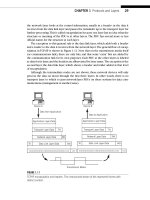
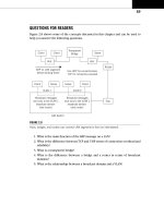
Now consider the server shown in Figure 12.2. Here there is a server that has more
than one TCP/IP interface for network access, and thus more than one IP address. Yet
these servers may still have only one FTP (or any other TCP/IP application) server process
304 PART II Core Protocols
running. With the socket concept, the FTP server process has no problem separating
client FTP sessions from different network interfaces because their socket identifi ers
will differ on the server end. Since a TCP connection is always identifi ed by both the cli-
ent and server IP address and the client and server port numbers, there is no confusion.
This illustrates the sockets concept in more depth, but not the use of the socket
interface in a TCP/IP network. The socket interface forms the boundary between the
application program written by the programmer and the network processes that are
usually bundled with the operating system and quite uniform compared to the myriad
of applications that have been implemented with programs.
Socket Libraries
Developers of applications for TCP/IP networks will frequently make use of a sockets
library to implement applications. These applications are not the standard “bundled”
TCP/IP applications like FTP, but other applications for remote database queries and
the like that must run over a TCP/IP network. The sockets library is a set of program-
ming tools used to simplify the writing of application programs for TCP or UDP. Since
these “custom” applications are not included in the regular application services layer
of TCP/IP, these applications must interface directly with the TCP/IP stack. Of course,
these applications must also exist in the same client–server, active–passive open envi-
ronment as all other TCP/IP applications.
The socket is the programmer’s identifi er for this TCP/IP layer interface. In Unix
environments, the socket is treated just like a fi le. That is, the socket is created, opened,
read from, written to, closed, and deleted, which are exactly the same operations that
a programmer would use to manipulate a fi le on a local disk drive. Through the use of
the socket interface, a developer can write TCP/IP networked client–server applica-
tions without thinking about managing TCP/IP connections on the network.
The programmer can use sockets to refer to any remote TCP/IP application layer
entity. Many developers use socket interfaces to provide “front-end” graphical interfaces
FTP Process
Socket 1:
172.16.24.17:22
Socket 2:
172.16.43.11:22
172.16.24.17 172.16.43.11
FIGURE 12.2
The concept of sockets applied to FTP. Note how sockets allow a server with two different IP
addresses to access the FTP server process using the same port.
CHAPTER 12 Multiplexing and Sockets 305
to common remote TCP/IP server processes such as FTP. Of course, the developers may
choose to write applications that implement both sides of the client–server model.
The socket can interface with either TCP (called a “stream” socket), UDP (called a
“datagram” socket), or even IP directly (called the “raw” socket). Figure 12.3 shows the
three major types of socket programming interfaces. There are even socket libraries
that allow interfaces with the frames of the network access layer below IP itself. More
details must come from the writers of the sockets libraries themselves, since socket
libraries vary widely in operational specifi cs.
TCP Stream Service Calls
When used in the stream mode, the socket interface supplies the TCP protocol with
the proper service calls from the application. These service calls are few in number,
but enough to completely activate, maintain, and terminate TCP connections on the
TCP/IP network. Their functions are summarized in the following:
OPEN—Either a passive or active open is defined to establish TCP connections.
SEND—Allows a client or server application process to pass a buffer of informa-
tion to the TCP layer for transmission as a segment.
RECEIVE—Prepares a receive buffer for the use of the client or server application
to receive a segment from the TCP layer.
STATUS—Allows the application to locate information about the status of a TCP
connection.
CLOSE—Requests that the TCP connection be closed.
Application Programs
Stream
Interface
Network
Datagram
Interface
Raw Socket
Interface
TCP UDP
IP Layer
FIGURE 12.3
The three socket types. Note that the raw socket interface bypasses TCP and UDP. (The socket
program often builds its own TCP or UDP header.)
306 PART II Core Protocols
ABORT—Asks that the TCP connection discard all data in buffers and terminate
the TCP connection immediately.
These commands are invoked on the application’s behalf by the socket interface,
and therefore are not seen by the application programmer. But it is always good to
keep in mind that no matter how complicated a sockets library of routines might seem
to a programmer, at heart the socket interface is a relatively simple procedure.
THE SOCKET INTERFACE: GOOD OR BAD?
However, the very simplicity of socket interfaces can be deceptive. The price of this
simplicity is isolating the network program developers from any of the details of how
the TCP/IP network actually operates. In many cases, the application programmers
interpret this “transparency” of the TCP/IP network (“treat it just like a fi le”) to mean
that the TCP/IP network really does not matter to the application program at all.
As many TCP/IP network administrators have learned the hard way, nothing could
be further from the truth. Every segment, datagram, frame, and byte that an applica-
tion puts on a TCP/IP network affects the performance of the network for everyone.
Programmers and developers that treat sockets “just like a fi le” soon fi nd out that the
TCP/IP network is not as fast as the hard drive on their local systems. And many appli-
cations have to be rewritten to be more effi cient just because of the seductive transpar-
ency of the TCP/IP network using the socket interface.
For those who have been in the computer and network business almost from the
start, the socket interface controversy in this regard closely mirrors the controversy that
erupted when COBOL, the fi rst “high-level” programming language, made it possible for
people who knew absolutely nothing about the inner workings of computers to be
trained to write application programs. Before COBOL, programmers wrote in a low-level
assembly language that was translated (assembled) into machine instructions. (Some
geniuses wrote directly in machine code without assemblers, a process known as “bare
metal programming.”)
Proponents then, as with sockets, pointed out the effi ciencies to be enjoyed by
freeing programmers from reinventing the wheel with each program and writing
the same low-level routines over and over. There were gains in production as well—
programmers who wrote a single instruction in COBOL could rely on the compiler
to generate about 10 lines of underlying assembly language and machine code. Since
programmers all wrote about the same number of lines of code a day, a 10-fold gain in
productivity could be claimed.
The same claims regarding isolation are often made for the socket interface. Freed
from concerns about packet headers and segments, network programmers can con-
centrate instead on the real task of the program and benefi t from similar productivity
gains. Today, no one seriously considers the socket interface to be an isolation liabil-
ity, although similar claims of “isolation” are still heard when programmers today can
generate code by pointing and clicking at a graphical display in Visual Basic or another
even higher level “language.”
CHAPTER 12 Multiplexing and Sockets 307
The “Threat” of Raw Sockets
A more serious criticism of the socket interface is that it forms an almost perfect tool
for hackers, especially the raw socket interface. Many network security experts do not
look kindly on the kind of abuses that raw sockets made possible in the hands of
hackers.
Why all the uproar over raw sockets? With the stream (TCP) and datagram (UDP)
socket interfaces, the programmer is limited with regard to what fi elds in the TCP/UDP
or IP header that they can manipulate. After all, the whole goal is to relieve the program-
mer of addressing and header fi eld concerns. Raw sockets were originally intended as
a protocol research tool only, but they proved so popular among the same circle of
trusted Internet programmers at the time that use became common.
But raw sockets let the programmer pretty much control the entire content of the
packet, from header to fl ags to options. Want to generate a SYN attack to send a couple
of million TCP segments with the SYN bit sent one after the other to the same Web
site, and from a phony IP address? This is diffi cult to do through the stream socket, but
much easier with a raw socket. Consequently, this is one reason why you can fi nd and
download over the Internet hundreds of examples using TCP and UDP sockets, but raw
socket examples are few and far between. Not only could users generate TCP and UPD
packets, but even “fake” ICMP and traceroute packets were now within reach.
Microsoft unleashed a storm of controversy in 2001 when it announced support
for the “full Unix-style” raw socket interface in Windows XP. Limited support for raw
sockets in Windows had been available for years, and third-party device drivers could
always be added to Windows to support the full raw socket interface, but malicious
users seldom bestirred themselves to modify systems that were already in use. How-
ever, if a “tool” was available to these users, it would be exploited sooner or later.
Many saw the previous limited support for raw sockets in Windows as a blessing
in disguise. The TCP/UDP layers formed a kind of “insulation” to protect the Internet
from malicious application programs, a protective layer that was stripped away with
full raw socket support. They also pointed out that the success of Windows NT servers,
and then Windows 95/98/Me, all of which lacked full raw socket support, meant that
no one needed full raw sockets to do what needed doing on the Internet. But once full
raw sockets came to almost everyone’s desktop, these critics claimed, hackers would
have a high-volume, but poorly secured, operating system in the hands of consumers.
Without full raw sockets, Windows PCs could not spoof IP addresses, generate TCP
segment SYN attacks, or create fraudulent TCP connections. When taken over by email-
delivered scripts in innocent-looking attachments, these machines could become “zom-
bies” and be used by malicious hackers to launch attacks all over the Internet.
Microsoft pointed out that full raw sockets support was possible in previous edi-
tions of Windows, and that “everybody else had them.” Eventually, with the release of
Service Pack 2 for Windows XP, Microsoft restricted the traffi c that could be sent over
the raw socket interface (receiving was unaffected) in two major ways: TCP data could
not be sent and the IP source address for UDP data must be a valid IP address. These
changes should do a lot to reduce the vulnerability on Windows XP in this regard.
308 PART II Core Protocols