The Illustrated Network- P39 pdf
Bạn đang xem bản rút gọn của tài liệu. Xem và tải ngay bản đầy đủ của tài liệu tại đây (119.3 KB, 10 trang )
Now, let’s see what it takes to get RIPng up and running on these routers. So far, the
link-local fe80 addresses have been fi ne for running ping and for neighbor discovery
from router to host, but these won’t be useful for LAN1 to LAN2 communications with
IPv6. For this, we’ll use routable fc00 private ULA IPv6 addresses. Once we get RIPng
up and running with routable addresses on our hosts and routers, we should be able to
successfully ping from LAN1 to LAN2 using only IPv6 addresses. While we’ll be confi g-
uring IGPs on both Ace and Best ISP’s AS routing domains, we won’t be running IGPs
between them. That’s the job of the EGP (Border Gateway Protocol, or BGP), and we’ll
add that in Chapter 15.
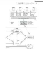
We need to create four routable IPv6 addresses and prefi xes—two for the hosts
and two for the router’s LAN interfaces (both are fe-1/3/0). We’ve already done this in
Chapter 4. The site IPv6 addresses, and the IPv4 and MAC addresses used on the same
interfaces, are shown in Table 14.1. We don’t need to change the link-local addresses on
the link between the routers because, well, they are link-local.
We know from Chapter 13 that we have these IPv6 addresses confi gured on wincli1
and wincli2. We have to do three things to enable RIPng on the routers:
■ Confi gure routable addresses on interface fe-1/3/0
■ Confi gure the RIPng protocol to run on the site (customer-edge) routers (CE0 and
CE6), the provider-edge routers (PE5 and PE1), and the internal links on the provider-
backbone routers (P9, P7, P4, and P2).
■ Create and apply a routing policy on CE0 and CE6 to advertise the fe-1/3/0 IPv6
addresses with RIPng.
Since 2007, ASNs are allocated as 4-byte values. Because each fi eld can run
from 0 to 65535, the current way of designating ASNs is as two numbers in the
form nnnnn.nnnnnn. The full range of ASNs now is from 0.0 to 65535.65535
(0 to 4,294,967,295 in decimal).
For example, 0.65525 is how the former 2-byte ASN 65535 would be written
today. In this book, we’ll drop the leading “0,” and just use the “legacy” 2-byte AS
format for Ace and Best ISP: 65459 and 65127.
Table 14.1 Routable IPv6 Addresses Used on the Network
System
IPv4 Network
Address MAC Address IPv6 Address
wincli1 10.10.11/24 02:0e:0c:3b:88:3c fc00:ffb3:d5:b:20e:cff:fe3b:883c
CE0 (fe-1/3/0) 10.10.11/24 00:05:85:88:cc:db fc00:ffb3:d5:b:205:85ff:fe88:ccdb
CE6 (fe-1/3/0) 10.10.12/24 00:05:85:8b:bc:db fc00:fe67:d4:c:205:85ff:fe8b:bcdb
Wincli2 10.10.12/24 00:02:b3:27:fa:8c fc00:fe67:d4:c:202:b3ff:fe27:fa8c
CHAPTER 14 IGPs: RIP, OSPF, and IS–IS 349
The confi gurations are completely symmetrical, so one of each type will do for
illustration purposes. Let’s use router CE0 as the customer-edge router. First, the
addresses for IPv4 (
family inet) and IPv6 (family net6) must be confi gured on LAN
interface fe-1/3/0.
set interfaces fe-1/3/0 unit 0 family inet address 10.10.11.1/24
set interfaces fe-1/3/0 unit 0 family inet6 address fe80::205:85ff:fe88:ccdb/64
s et interfaces fe-1/3/0 unit 0 family inet6 address fc00:fe67:d4:c:205:85ff:fe88:
ccdb/64
Note that the link-local address is fi ne as is. We usually have many addresses on
an interface in most IPv6 implementations, including multicast. We just added the
second address to it. Now we can confi gure RIPng itself on the link between CE0 and
PE5. We have to explicitly tell RIPng to announce (export) the routing information
specifi ed in the send-ipv6 routing policy (which we’ll write shortly) and tell it the
RIPng “ neighbor” (routing protocol partner) is found on interface ge-0/0/3 logical
unit 0.
set protocols ripng group ripv6group export send-ipv6
set protocols ripng group ripv6group neighbor ge-0/0/3.0
Because RIPv2 and RIPng use multicast addresses, we specify the router’s neigh-
bor location with the physical address information (ge-0/0/3) instead of unicast
address. And because Juniper Network’s implementation of RIP always listens for rout-
ing information but never advertises or announces routes unless told, we’ll have to
write a routing policy to “export” the IPv6 addresses we want into RIPng. There’s only
one interface needed in this case, fe-1/3/0.0 to LAN1. It seems odd to say from when
sending, but in a Juniper Networks routing policy, from really means “out of”—“Out of
all the interfaces, this applies to interface fe-1/3/0.”
set policy-options policy-statement send-ipv6 from interface fe-1/3/0.0
set policy-options policy-statement send-ipv6 from family inet6
set policy-options policy-statement send-ipv6 then accept
All this routing policy says is that “if the routing protocol (which is RIPng) running
on the LAN1 interface (fe-1/3/0) wants to advertise an IPv6 route (from family inet6),
let it (accept).”
We also have to confi gure RIPng on the other routers. We know that we can’t
run RIPng on the external links on the border routers (P7, P9, P2, and P4), but we
can show the full confi gurations on PE5 and PE1. These routers have to run RIPng
on three interfaces, not just one, so that RIPng routing information fl ows from site
router to backbone (and from backbone to site router). Let’s look at PE5 (PE1 is about
the same).
350 PART III Routing and Routing Protocols
set interfaces fe-1/3/0 unit 0 family inet address 10.10.50.1/24
set interfaces fe-1/3/0 unit 0 family inet6 address fe80::205:85ff:fe85:aafe/64
set interfaces fe-1/3/0 unit 0 family inet6 address fc00:fe67:d4:c:205:85ff:fe85:
aafe/64
We have IPv6 addresses on the SONET links to P9 and P4, so-0/0/0 and so-0/0/2,
but the details are not important. What is important is that we run RIPng on all three
interfaces.
set protocols ripng group ripv6group export send-ipv6
set protocols ripng group ripv6group neighbor ge-0/0/3.0
set protocols ripng group ripv6group neighbor so-0/0/0.0
set protocols ripng group ripv6group neighbor so-0/0/2.0
The routing policy now will export the interface IPv6 addresses we want into
RIPng. This policy has one term for each interface and is more complex than the one
for the site routers.
set policy-options policy-statement send-ipv6 term A from interface ge-0/0/3.0
set policy-options policy-statement send-ipv6 term A from family inet6
set policy-options policy-statement send-ipv6 term A then accept
set policy-options policy-statement send-ipv6 term B from interface so-0/0/0.0
set policy-options policy-statement send-ipv6 term B from family inet6
set policy-options policy-statement send-ipv6 term B then accept
set policy-options policy-statement send-ipv6 term C from interface so-0/0/2.0
set policy-options policy-statement send-ipv6 term C from family inet6
set policy-options policy-statement send-ipv6 term C then accept
The policy simply means this: “Out of all interfaces, look at ge-0/0/3, so-0/0/0, and
so-0/0/2. If the routing protocol running on those links (which is RIPng) wants to
advertise an IPv6 route (from family inet6), let it (accept).”
The backbone routers run RIPng on their internal interfaces, but the confi gurations
and policies are very similar to those on the provider-edge routers. We don’t need to
list those.
When all the confi gurations are committed and made active on the routers, we form
an adjacency and exchange IPv6 routing information with each neighbor according to
the policy. The IPv6 routing table on CE0 now shows the prefi x of LAN2 (fc00:fe67:
d4:c::/64) learned from CE6 with RIPng.
admin@CE0# show route table inet6 fc00:fe67:d4:c::/64
inet6.0: 38 destinations, 38 routes (38 active, 0 holddown, 0 hidden)
+ = Active Route, - = Last Active, * = Both
fc00:ffbe:d5:b::/64 *[RIPng/100] 01:15:19, metric 6, tag 0
to fc00:ffbe:d5:b::a00:3b01 via so-0/0/0.0
> to fc00:ffbe:d5:b::a00:2d01 via so-0/0/2.0
CHAPTER 14 IGPs: RIP, OSPF, and IS–IS 351
What does all this mean? We’ve learned this route with RIPng, and its preference is
100 (high compared to local interfaces, which are 0). When routes are learned in dif-
ferent ways from different protocols, the route with the lowest preference will be the
active route. The metric of 6 (hops) essentially shows that LAN2 is 6 routers away from
LAN1. If there are different paths with different metrics through a collection of routers,
the hop to the path with the lowest metric becomes the active route. More advanced
routing protocols can compute metrics on the basis of much more than simply number
of routers (hops).
Note the right angle bracket (
>) to the left of the so-0/0/2.0 link to router P9. Remem-
ber, there are two ways for PE5 to forward packets to LAN2: through router P4 at the end
of link so-0/0/0.0 and through router P9 at the end of link so-0/0/0.0. The > indicates
that packets are being forwarded to router P9. (Usually, all other things being equal, a
router chooses the link with the lower IP address.) However, the other link is available if
the active link or router fails. (If we want to forward packets out both links, we can turn
on load balancing and the links will be used in a round-robin fashion.)
But even with RIPng up and running among the routers, we still have to give non–
link-local addresses to the hosts. Right now, if we try to use ping6 on LAN2 to ping a
different IPv6 private address on LAN1, we’ll still get an error condition. Let’s try it from
wincli2 on LAN2 to wincl1 on LAN1.
C:\Documents and Settings\Owner>ping6 fe80::20c:cff:fe3b:883c
Pinging fe80::20c:cff:fe3b:883c with 32 bytes of data:
No route to destination.
Specify correct scope-id or use –s to specify source address.
No route to destination.
Specify correct scope-id or use –s to specify source address.
No route to destination.
Specify correct scope-id or use –s to specify source address.
No route to destination.
Specify correct scope-id or use –s to specify source address.
Ping statistics for fe80::20c:cff:fe3b:883c:
Packets: Sent = 4, Received = 0, Lost = 4 (100% loss)
Like the routers, the Windows XP hosts need routable addresses. We assign an inter-
face (by index shown by ipconfig) that is a routable IPv6 address with the ipv6 adu
command. But the address is still shown with ipconfig.
C:\Documents and Settings\Owner>ipconfig
Ethernet adapter Local Area Connection:
Connection-specific DNS Suffix . :
IP Address . . . . . . . . . . . : 10.10.12.222
Subnet Mask . . . . . . . . . . : 255.255.255.0
352 PART III Routing and Routing Protocols
IP Address . . . . . . . . . . . : fc00:fe67:d5:c:202:b3ff:fe27:fa8c
IP Address . . . . . . . . . . . : fe80::202:b3ff:fe27:fa8c%5
Default Gateway . . . . . . . . : 10.10.12.1
fe80::5:85ff:fe8b:bcdb%5
fc00:fe67:d5:c:205:85ff:fe8b:bcdb
How did the host know the default gateway to use for IPv6? We probed for neighbors
earlier, but even if we had not, IPv6 router advertisement (which was confi gured with
RIPng on the routers, and the main reason we did it) takes care of that.
Now we should be able to ping end to end from wincli2 to wincli1 by IPv6 address.
C:\Documents and Settings\Owner>ping6 fc00:ffb3:d4:b:20e:cff:fe3b:883c
Pinging fc00:ffb3:d.4:b:20e:cff:fe3b:883c
from fc00:fe67:d5:c:202:b3ff:fe27:fa8c with 32 bytes of data:
Reply from fc00:ffb3:d4:b:20e:cff:fe3b:883c: bytes=32 time<1ms
Reply from fc00:ffb3:d4:b:20e:cff:fe3b:883c: bytes=32 time<1ms
Reply from fc00:ffb3:d4:b:20e:cff:fe3b:883c: bytes=32 time<1ms
Reply from fc00:ffb3:d4:b:20e:cff:fe3b:883c: bytes=32 time<1ms
Ping statistics for fc00:ffb3:d4:b:20e:cff:fe3b:883c:
Packets: Sent = 4, Received = 4, Lost = 0 (0% loss),
Approximate round trip times in milli-seconds:
Minimum = 4ms, Maximum = 5ms, Average = 4ms
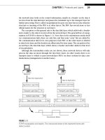
The reverse also works as well. In the rest of this chapter, let’s take a closer look
at how the IGPs perform their task of distributing routing information within an AS.
Remember, how the IGP routing information gets from AS to AS with an EGP is the
topic of Chapter 15.
INTERIOR ROUTING PROTOCOLS
Routers initially know only about their immediate environments. They know the IP
addresses and prefi xes confi gured on their local interfaces, and at most a little more
statically defi ned information. Yet all routers must know all the details about everything
in their routing domain to forward packets rationally, hop by hop, toward a given des-
tination. So routers offer to and ask their neighbor routers (adjacent routers one hop
away) about the routing information they know. Little by little, each router then builds
up a detailed routing information database about the TCP/IP network.
How do routers exchange this routing information within a domain and between
routing domains? With routing protocols. Within a routing domain, several different
routing protocols can be used. Between routing domains on the Internet, another rout-
ing protocol is used. This chapter focuses on the routing protocols used within a rout-
ing domain and the next chapter covers the routing protocol used between routing
domains.
CHAPTER 14 IGPs: RIP, OSPF, and IS–IS 353
Interior routing protocols, or IGPs, run between the routers inside a single routing
domain, or autonomous system (AS). A large organization or ISP can have a single AS,
but many global networks divide their networks into one or more ASs. IGPs run within
these routing domains and do not share information learned across AS boundaries
except physical interface addresses if necessary.
Modern routing protocols require minimal confi guration of static routes (routes
confi gured and maintained by hand). Today, dynamic routing protocols allow adjacent
(directly connected) routers to exchange routing table information periodically to build
up the topology of the router network as a whole by passing information received by
adjacent neighbors on to other routers.
IGPs essentially “bootstrap” themselves into existence, and then send information
about their IP addresses and interfaces to other routers directly attached to the source
router. These neighbor, or adjacent, routers distribute this information to their neigh-
bors until the network has converged and all routers have the identical information
available.
When changes in the network as a result of failed links or routers cause the rout-
ing tables to become outdated, the routing tables differ from router to router and are
inconsistent. This is when routing loops and black holes happen. The faster a routing
protocol converges, the better the routing protocol is for large-scale deployment.
THE THREE MAJOR IGPs
There are three main IGPs for IPv4 routing: RIP, OSPF, and IS–IS. The Routing Informa-
tion Protocol (RIP), often declared obsolete, is still used and remains a popular routing
protocol for small networks. The newer version of RIP, known as RIPv2, should always
be used for IPv4 routing today. Open Shortest Path First (OSPF) and Intermediate
System–Intermediate System (IS–IS) are similar and much more robust than RIP. There
are versions of all three for IPv6: OSPFv3, RIPng (sometimes seen as RIPv6), and IS–IS
works with either IPv4 or IPv6 today.
RIP is a distance-vector routing protocol, and OSPF and IS–IS are link-state routing
protocols. Distance-vector routing protocols are simple and make routing decisions
based on one thing: How many routers (hops) are there between here and the destina-
tion? To RIP, link speeds do not matter, nor does congestion near another router. To RIP,
the “best” route always has the fewest number of hops (routers).
Link-state protocols care more about the network than simply the number
of routers along the path to the destination. They are much more complex than
distance-vector routing protocols, and link-state protocols are much more suited
for networks with many different link speeds, which is almost always the case
today. However, link-state protocols require an elaborate database of information
about the network on each router. This database includes not only the local router
addressing and interfaces, but each and every router in the immediate area and
often the entire AS.
354 PART III Routing and Routing Protocols
ROUTING INFORMATION PROTOCOL
The RIP is still used on all types of TCP/IP networks. The basics of RIP were spelled out
in RFC 1058 from 1988, but this is misleading. RIP was in use long before 1988, but no
one bothered to document RIP in detail. RIP is bundled with almost all implementa-
tions of TCP/IP, so networks often run only RIP. Why pay for something when RIP was
available for free?
RIP version 1 (RIPv1) in RFC 1058 has a number of annoying limitations, but RIP
is so popular that doing away with RIP is not a realistic consideration. RFC 1388 intro-
duced RIP version 2 (RIPv2 or sometimes RIP-2) in 1993. RIPv2 addressed RIPv1 limita-
tions, but could not turn a distance-vector protocol into a link-state routing protocol
such as OSPF and IS–IS.
RIPv2 is backward compatible with RIPv1, and most RIP implementations run RIPv2
by default and allow RIPv1 to be confi gured. In this chapter, the term “RIP” by itself
means “a version of RIP runs RIPv2 by default but can also be confi gured as RIPv1 as
required.”
Router vendor Cisco was deeply dissatisfi ed with RIPv1 limitations and so created
its own vendor-specifi c (proprietary) version of an IGP routing protocol, which Cisco
called the Interior Gateway Routing Protocol (IGRP). IGRP improved upon RIPv1 in
several ways, but “pure” IGRP could only run between Cisco routers. As good as IGRP
was, IGRP was still basically implemented as a distance-vector protocol. As networks
grew more and more complex in terms of link speeds and router capacities, it was pos-
sible to switch to a link-state protocol such as OSPF or IS–IS, but many network admin-
istrators at the time felt these new protocols were not stable or mature enough for
production networks. Cisco then invented Enhanced IGRP (EIGRP) as a sort of “hybrid”
routing protocol that combined features of both distance-vector and link-state routing
protocols all in one (proprietary) package.
Due to the proprietary nature of IGRP and EIGRP, only the basics of these routing
protocols are covered in this chapter.
Distance-Vector Routing
RIP and related distance-vector routing protocols are classifi ed as “Bellman–Ford” routing
protocols because they all choose the “best” path to a destination based on the shortest
path computation algorithm. It was fi rst described by R. E. Bellman in 1957 and applied
to a distributed network of independent routers by L. R. Ford, Jr. and D. R. Fulkerson in
1962. Every version of Unix today bundles RIP with TCP/IP, usually as the routed (“route
management daemon”) process, but sometimes as the gated process.
All routing protocols use a metric (measure) representing the relative “cost” of send-
ing a packet from the current router to the destination. The lowest relative cost is the
“best” way to send a packet. Distance-vector routing protocols have only one metric:
distance. The distance is usually expressed in terms of the number of routers between
the router with the packet and the router attached to the destination network. The
CHAPTER 14 IGPs: RIP, OSPF, and IS–IS 355
distance metric is carried between routers running the same distance-vector routing
protocol as a vector, a fi eld in a routing protocol update packet.
A simple example of how distance-vector, or hop-count, routing works will illustrate
many of the principles that all routing protocols simple and complex must deal with. All
routing protocols must pass along network information received from adjacent rout-
ers to all other routers in a routing domain, a concept known as fl ooding. Flooding is
the easiest way to ensure consistency of routing tables, but convergence time might
be high as routers at one end of a chain of routers wait for information from routers at
the far end of the chain to make its way through the routers in between. Flooding also
tends to maximize the bandwidth consumed by the routing protocol itself, but there
are ways to reduce this.
RIP fl oods updates every 30 seconds. Note that routing information takes at least 30
seconds to reach the closest neighbor if that is the routing update interval used. Long
chains of routers can take quite a long time to converge (several minutes) when a net-
work address is added or when a link fails.
When this network converges, each routing table will be consistent and each router
will be reachable from every other router over one of the interfaces. The network
topology has been “discovered” by the routing protocol. An example of the information
in one of these tables is shown in Table 14.2.
Routers can have alternatives other than those shown in the table. For example, the
cost to reach network 192.168.44.0 from this router could be the same (3) over E1 as
it is over E2. The E1 interface is most likely in the table because the update from the
neighbor router saying “send 192.168.44.0 packets here” arrived before the update
from another router saying the same thing, or the entry was already in the table. When
costs are equal, routing tables tend to keep what they know.
Broken Links
The distance-vector information has now been exchanged and the routers all have a
way to reach each other. Usually, the routing protocol will update an internal database
in the router just for that routing protocol and one or more entries based on the data-
base are made in the routing table, which might contain information from other rout-
ing protocols as well. The routing table information is then used to compute the “best”
routes to be used in the forwarding table (sometimes called the switching table) of the
Table 14.2 Example RIP Routing Table
Network Next Hop Interface Cost
10.0.14.0 Ethernet 1 (E1) 2
172.16.15.0 Serial 1 (S1) 1
192.168.44.0 Ethernet 2 (E2) 3
192.168.66.0 Serial 2 (S2) INF (15)
192.168.78.0 Locally attached 0
356 PART III Routing and Routing Protocols
router. This chapter blurs the distinctions between routing protocol database, routing
table, and forwarding table for the sake of simplicity and clarity.
What will happen to the network if a link “breaks” and can no longer be used to
forward traffi c? In a static routing world, this would be disastrous. But when using a
dynamic routing protocol, even one as simple as a distance-vector routing protocol, the
network should be able to converge around the new topology.
The routers at each end of the link, since they are locally connected to the interface
(direct), will notice the outage fi rst because routers constantly monitor the state of
their interfaces at the physical level. Distance-vector protocols note this absent link by
noting that the link now has an “infi nite” cost. All routers formerly reachable through
the link are now an infi nite distance away.
Distance-Vector Consequences
In some cases, distance-vector updates are generated so closely in time by different
routers that a link failure can cause a routing loop to occur, and packets can easily
“bounce” back and forth between two adjacent routers until the packet TTL expires,
even though the destination is reachable over another link. The “bouncing effect” will
last until the network converges on the new topology.
However, this convergence can take some time, since routers not located at the end
of a failed link have to gradually increase their costs to infi nity one “hop” at a time. This
is called “counting to infi nity,” and can drag out convergence time considerably if the
value of “infi nity” is set high enough. On the other hand, a low value of “infi nity” will
limit the maximum number of routers that can form the longest path through the net-
work from source to destination.
In order to minimize the effects of bouncing and counting to infi nity, most imple-
mentations of distance-vector routing protocols such as RIP also implement split hori-
zon and triggered updates.
Split Horizon
If Router A is sending packets to Router B to reach Router E, then it makes no sense at
all for Router B to try to reach Router E through Router A. All Router A will do is turn
around and send the packet right back to Router B. So Router A should never advertise
a way to reach Router E to Router B.
A more sophisticated form of split horizon is known as split horizon with poison
reverse. Split horizon with poison reverse eliminates a lot of counting to infi nity prob-
lems due to single link failures. However, many multiple link failures will still cause
routing loops and counting to infi nity problems even when split horizon with poison
reverse is in use.
Triggered Updates
With triggered updates, a router running a distance-vector protocol such as RIP can
remain silent if there are no changes to the information in the routing table. If a link
failure is detected, triggered updates will send the new information. Triggered updates,
CHAPTER 14 IGPs: RIP, OSPF, and IS–IS 357
like split horizon, will not eliminate all cases of routing loops and counting to infi nity.
However, triggered updates always help the counting process to reach infi nity much
faster.
RIPv1
A RIP packet must be 512 bytes or smaller, including the header. RIP packets have no
implied sequence, and each update packet is processed independently by the router
receiving the update. A router is only required to keep one entry associated with each
route. But in practice, routers might keep up to four or more routes (next hops) to the
same destination so that convergence time is lowered.
RIPv1 required routers running RIP to broadcast the entire contents of their rout-
ing tables at fi xed intervals. On LANs, this meant that the RIPv1 packets were sent
inside broadcast MAC frames. But broadcast MAC frames tell not only every router on
the LAN, but every host on the LAN, “pay attention to this frame.” Inside the frame, the
host would fi nd a RIPv1 update packet, and probably ignore the contents. But every
30 seconds, every host on the LAN had to interrupt its own application processing and
start throwing away RIPv1 packets.
Each host could keep the information inside the RIPv1 update packet. Some hosts
on LANs with RIPv1 routers have as elaborate a routing table as the routers themselves.
Hackers loved RIPv1: With a few simple coding changes, any host could impersonate
a RIPv1 router and start pumping out fake routing information, as many college and
university network administrators discovered in the late 1980s. (This is one reason you
don’t run RIP on host interfaces.)
Many people see RIP updates vary from 30 seconds and assume that timers are off.
In fact, table updates in RIP are initiated on each router at approximate 30-second
intervals. Strict synchronization is avoided because RIP traffi c spikes can easily lead to
discarded RIP packets. The update timer usually adds or subtracts a small amount of
time to the 30-second interval to avoid RIP router synchronization.
Network devices running RIP can be either active or passive (silent) mode. Active
RIP devices will listen for RIP update packets and also generate their own RIP update
packets. Passive RIP devices will only listen for RIP updates and never generate their
own update packets. Many hosts, for example, which must process the broadcast RIP
updates sent on a LAN, are purely passive RIP devices.
RIPv1 Limitations
RIPv1 had a number of limitations that made RIPv1 diffi cult to use in large networks. The
larger the routing domain, the more severe and annoying the limitations of RIPv1
become.
Wasted Space—All of the RIPv1 packet fields are larger than they need to be,
sometimes many times larger. There are almost three times as many 0 bits as
information bits in a RIP packet.
358 PART III Routing and Routing Protocols