The Illustrated Network- P40 docx
Bạn đang xem bản rút gọn của tài liệu. Xem và tải ngay bản đầy đủ của tài liệu tại đây (214.39 KB, 10 trang )
Limited Metrics—As a network grows, the distance-vector might require a metric
greater than 15, which is unreachable (infinite).
No Link Speed Allowances—The simple hop count metric will always result in
packets being sent (as an example) over two hops using low-speed, 64-kbps
links rather than three hops using SONET/SDH links.
No Authentication—RIPv1 devices will accept RIPv1 updates from any other
device. Hackers love RIPv1 for this very reason, but even an innocently mis-
configured router can disrupt an entire network using RIPv1.
Subnet Masks—RIPv1 requires the use of the same subnet mask because RIPv1
updates do not carry any subnet mask information.
Slow Convergence—Convergence can be very slow with RIPv1, often 5 minutes
or more when links result in long chains of routers instead of neat meshes. And
“circles” of RIPv1 routers maximize the risk of counting to infinity.
RIPv2
RIPv2 fi rst emerged as an update to RIPv1 in RFC 1388 issued in January 1993. This
initial RFC was superseded by RFC 1723 in November 1994. The only real difference
between RFC 1388 and RFC 1723 is that RFC 1723 deleted a 2-byte Domain fi eld
from the RIPv2 packet format, designating this space as unused. No one was really
sure how to use the Domain fi eld anyway. The current RIPv2 RFC is RFC 2453 from
November 1998.
RIPv2 was not intended as a replacement for RIPv1, but to extend the functions of
RIPv1 and make RIP more suitable for VLSM. The RIP message format was changed as
well to allow for authentication and multicasting.
In spite of the changes, RIPv2 is still RIP and suffers from many of the same limita-
tions as RIPv1. Most router vendors support RIPv2 by default, but allow interfaces or
whole routers to be confi gured for backward compatibility with RIPv1. RIPv2 made
major improvements to RIPv1:
■ Authentication between RIP routers
■ Subnet masks to be sent along with routes
■ Next hop IP addresses to be sent along with routes
■ Multicasting of RIPv2 messages
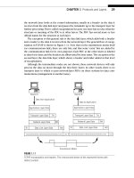
The RIPv2 packet format is shown in Figure 14.2.
Command Field (1 byte)—This is the same as in RIPv1: A value of 1 is for a
Request and a value of 2 is for a Response.
Version Number (1 byte)—RIPv1 uses a value of 1 in this field, and RIPv2 uses a
value of 2.
CHAPTER 14 IGPs: RIP, OSPF, and IS–IS 359
Unused (2 bytes)—Set to all zero bits. This was the Domain field in RFC 1388.
Now officially unused in RFC 1723, this field is ignored by routers running
RIPv2 (but this field must be set to all 0 bits for RIPv1 routers).
Address Family Identifier (AFI) (2 bytes)—This field is set to a value of 2 when
IP packet and routing information is exchanged. RIPv2 also defined a value of
1 to ask the receiver to send a copy of its entire routing table. When set to all
1s (0xFFFF), the AFI field is used to indicate that the 16 bits following the AFI
field, ordinarily set to 0 bits, now carry information about the type of authen-
tication being used by RIPv2 routers.
Authentication or Route Tag (2 bytes)—When the AFI field is not 0xFFFF, this
is the Route Tag field. The Route Tag field identifies internal and external
routes in RIPv2. Internal routes are those learned by RIP itself, either locally
or through other RIP routers. External routes are routes learned from another
routing protocol such as OSPF or BGP.
IPv4 Address (4 bytes)—This field and the three that follow can be repeated up
to 25 times in the RIPv2 Response packet. This field is almost the same as in
1 byte
R
o
u
t
e
E
n
t
r
y
R
o
u
t
e
E
n
t
r
y
Command Version
Address Family Identifier
Address Family Identifier
Authentication or Route Tag
Authentication or Route Tag
Subnet Mask
Next Hop
IP Address
Metric
Subnet Mask
Next Hop
IP Address
Metric
32 bits
(Repeats multiple times,up to a maximum of 25)
Unused (set to all zeros)
1 byte 1 byte 1 byte
FIGURE 14.2
RIPv2 packet format, showing how the subnet mask is included with the routing information
advertised.
360 PART III Routing and Routing Protocols
RIPv1. This address can be a host route, a network address, or a default route.
A RIPv2 Request packet has the IP address of the originator in this field.
Subnet Mask (4 bytes)—This field, the biggest change in RIPv2, contains the sub-
net mask that goes with the IP address in the previous field. If the network
address does not use a subnet mask different from the natural classful major
network mask, then this field can be set to all zeroes, just as in RIPv1.
Next Hop (4 bytes)—This field contains the next hop IP address that traffic to this
IP address space should use. This was a vast improvement over the “implied”
next hop used in RIPv1.
Metric (4 bytes)—Unfortunately, the metric field is unchanged. The range is still 1
to 15, and a metric value of 16 is considered unreachable.
RIPv2 is still RIP. But RIPv2’s additions for authentication, subnet masks, next
hops, and the ability to multicast routing information increase the sophistication of RIP
and have extended RIP’s usefulness.
Authentication
Authentication was added in RIPv2. The Response messages contain the routing
update information, and authenticating the responder to a Request message is a good
way to minimize the risk of a routing table becoming corrupted either by accident or
through hacker activities. However, there were really only 16 bits available for authen-
tication, hardly adequate for modern authentication techniques. So the authentication
actually takes the place of one routing table entry and authenticates the entire update
message. This gives 16 bytes (128 bits) for authentication, which is not state of the art,
but is better than nothing.
The really nice feature of RIPv2 authentication is that router vendors can add their
own Authentication Type values and schemes to the basics of RIPv2, and many do. For
example, Cisco and Juniper Networks routers can be confi gured to use MD5 (Message
Digest 5) authentication encryption to RIPv2 messages. Thus, most routers can have
three forms of authentication on RIP interfaces: none, simple password, or MD5. Natu-
rally, the MD5 authentication keys used must match up on the routers.
Subnet Masks
The biggest improvement from RIPv1 to RIPv2 was the ability to carry the subnet mask
along with the route itself. This allowed RIP to be used in classless IP environments
with VLSM.
Next Hop Identifi cation
Consider a network where there are several site routers with only one or a few small
LANs. The small routers run RIPv2 between themselves and their ISP’s router, but might
run a higher speed link to one router and a lower speed link to another. The higher
speed link might be more hops away than the lower speed link.
CHAPTER 14 IGPs: RIP, OSPF, and IS–IS 361
The next hop fi eld in RIPv2 is used to “override” the ordinary metric method of
deciding active routes in RIP. RIPv2 routers check the next hop fi eld in the routing
update message. If the next hop fi eld is set for a particular route, the RIP router will use
this as the next hop for the route, regardless of distance-vector considerations.
This RIPv2 next hop mechanism is sometimes called source routing in some docu-
ments. But true source routing information is always set by a host, not a router. This is
just RIPv2 next hop identifi cation.
Multicasting
Multicasting is a kind of “halfway” distribution method between unicast (one source
to one destination) and broadcast (one source to all possible destinations). Unlike
broadcasts that are received by all nodes on the subnet, only devices that join the
RIPv2 multicast group will receive packets for RIPv2. (We’ll talk more about multi-
cast in Chapter 16.) RIPv2 multicasting also offers a way to fi lter out RIPv2 messages
from a RIPv1 only router. This can be important, since RIPv2 messages look very much
like RIPv1 messages. But RIPv2 messages are all invalid by RIPv1 standards. RIPv1
devices would either discard RIPv2 messages because the mandatory all-zero fi elds are
not all zeroes, or accept the routes and ignore the additional RIPv2 information such
as the subnet mask. RIPv2 multicasting makes sure that only RIPv2 devices see the
RIPv2 information. So RIPv1 and RIPv2 routers can easily coexist on the same LAN, for
instance. The multicast group used for RIPv2 routers is 224.0.0.9.
RIPv2 is still limited in several ways. The 15 maximum-hop count is still there, as
well as counting to infi nity to resolve routing loops. And RIPv2 does nothing to improve
on the fi xed distance-vector values that are a feature of all versions of RIP.
RIPng for IPv6
The version of RIP used with IPv6 is called RIPng, where “ng” stands for “next genera-
tion.” (IPv6 itself was often called IPng in the mid-1990s.) RIPng uses exactly the same
hop count metric as RIP as well as the same logic and timers. So RIPng is still a distance-
vector RIP, with two important differences.
1. The packet formats have been extended to carry the longer IPv6 addresses.
2. IPv6 security mechanisms are used instead of RIPv2 authentication.
The overall format of the RIP packet is the same as the format of the RIPv2 packet
(but RIPng cannot be used by IPv4). There is a 32-bit header followed by a set of 20-byte
route entries. The header fi elds must be the same as those used in RIPv2: There is a
1-byte Command code fi eld, followed by a 1-byte Version fi eld (now 6), and then 2 unused
bytes of bits that must still be set to all 0 bits. However, the 20-byte router entry fi elds in
RIPng are totally different that those in RIPv2.
IPv6 addresses are 16 bytes long, leaving only 4 bytes for any other information that
must be associated with the IPv6 route. First, there is a 2-byte Route Tag fi eld with the
same use as in RIPv2: The Route Tag fi eld identifi es internal and external routes. Inter-
nal routes are those learned by RIP itself, either locally or through other RIP routers.
362 PART III Routing and Routing Protocols
External routes are routes learned from another routing protocol such as OSPF or
BGP. Then there is a 1-byte Prefi x Length fi eld that tells the receiver where the bound-
ary between network and host is in the IPv6 address. Finally, there is a 1-byte Metric
fi eld (this fi eld was a full 32 bits in RIPv1 and RIPv2). Since infi nity is still 16 in RIPng,
this is not a problem.
The fi elds of the RIPng packet are shown in Figure 14.3. The combination of IPv6
address and Prefi x Length do away with the need for the Subnet Mask fi eld in RIPv2
packets. The Address Format Identifi er (AFI) fi eld from RIPv2 is not needed in RIPng,
since only IPv6 routing information can be carried in RIPng.
But IPv6 still needs a Next Hop fi eld. This RIPv2 fi eld contained the next-hop IP
address that traffi c to this IP address space should use, and was a vast improvement
over the “implied” next hop used in RIPv1. Now, IPv6 does not always need this Next
Hop information, but in many cases the next hop should be included in an IPv6 routing
information update. An IPv6 Next Hop needs another 128 bits (16 bytes). The creators
of RIPng decided to essentially reproduce the same route entry structure for the IPv6
Next Hop, but use a special value of the last fi eld (the Metric) to indicate that the fi rst
16 bytes in the route entry was an IPv6 Next Hop, not the route itself. The value chosen
for the metric was 256 (0xFF) because this was far beyond the legal hop count limit
(15) for RIP.
1 byte 1 byte 1 byte 1 byte
Unused (set to all zeros)VersionCommand
IPv6 Address
IPv6 Address
Route Tag
(Repeats multiple times, up to a maximum of 25)
Prefix Length Metric
Route Tag Prefix Length Metric
32 bits
R
o
u
t
e
E
n
t
r
y
R
o
u
t
e
E
n
t
r
y
FIGURE 14.3
RIPng for IPv6 packet fi elds. Note the large address fi elds and different format than RIPv2 fi elds.
CHAPTER 14 IGPs: RIP, OSPF, and IS–IS 363
When the route entry used is an IPv6 Next Hop, the 3 bytes preceding the 0xFF
Metric must be set to all 0 bits. This is shown in Figure 14.4.
At fi rst it might seem that the amount of the IPv6 routing information sent with
RIPng must instantly double in size, since now each 20-byte IPv6 route requires a
20-byte IPv6 Next Hop fi eld. This certainly would make IPv6 very unattractive to cur-
rent RIP users. But it was not necessary to include a Next Hop entry for each and every
IPv6 route because the creators of RIPng used a clever mechanism to optimize the use
of the Next Hop entry.
A Next Hop always qualifi es any IPv6 routes that follow it in the string of route
entries until another Next Hop entry is reached or the packet stream ends. This keeps
the number of “extra” Next Hop entries needed in RIPng to an absolute minimum. And
due to the fact that the Next Hop fi eld in RIPv2 has only specialized use, a lot of IPv6
routes need no Next Hop entry at all.
The decision to replace RIPv2 authentication with IPv6 security mechanisms was
based on the superior security used in IPv6. When used with RIPng updates, the IPv6
Authentication Header protects both the data inside the packet and the IP addresses of
the packet, but this is not the case with RIPv2 authentication no matter which method
is used. And IPv6 encryption can be used to add further protection.
A NOTE ON IGRP AND EIGRP
Cisco routers often use a proprietary IGP known as the Interior Gateway Routing
Protocol (IGRP) instead of RIP. Later, features were added to IGRP in the form of
Enhanced IGRP (EIGRP). In spite of the name, EIGRP was a complete redesign of
IGRP. This section will only give a brief outline of IGRP and EIGRP, since IGRP/EIGRP
interoperability with Juniper Networks routers is currently impossible.
IGRP and EIGRP might appear to be open standards, but this is only due to the wide-
ranging deployment of Cisco routers. Cisco has never published the details of IGRP
internals (EIGRP is based on these), and is not likely to.
1 byte 1 byte 1 byte 1 byte
Next Hop IPv6 Address
Must Be All Zeros
32 bits
Metric 5 0xFF
FIGURE 14.4
The Next Hop in IPv6 with RIPng. Note the use of the special metric value.
364 PART III Routing and Routing Protocols
IGRP improves on RIP in several areas, but IGRP is still essentially a distance-vector
routing protocol. EIGRP, on the other hand, is advertised by Cisco as a “hybrid” rout-
ing protocol that includes aspects of link-state routing protocols such as OSPF and
IS–IS among the features of EIGRP. Today not many, even those with all-Cisco networks,
would consider running EIGRP over OSPF or IS–IS.
Open Shortest Path First
OSPF is not a distance-vector protocol like RIP, but a link-state protocol with a set of
metrics that can be used to refl ect much more about a network than just the number
of routers encountered between source and destination. In OSPF, a router attempts to
route based on the “state of the links.”
OSPF can be equipped with metrics that can be used to compute the “shortest” path
through a group of routers based on link and router characteristics such as highest
throughput, lowest delay, lowest cost (money), link reliability, or even more. OSPF is still
used very cautiously, with default metrics based entirely on link bandwidth. Even with
this conservative use, OSPF link states are an improvement over simple hop counts.
Distance-vector routing protocols like RIP were fi ne for networks comprised of
equal speed links, but struggled when networks started to be built out of WAN links
with a wide variety of available speeds. When RIP fi rst appeared, almost all WANs were
composed of low-speed analog links running at 9600 bps. Even digital links running at
56 or 64 kbps were mainly valued for their ability to carry fi ve 9600-bps channels on
the same physical link. Commercial T1s at 1.544 Mbps were not widely available until
1984, and then only in major metropolitan areas. Today, the quickest way to send pack-
ets from one router to another is not always through the fewest number of routers.
The “open” in OSPF is based on the fact that the Shortest Path First (SPF) algorithm
was not owned by anyone and could be used by all. The SPF algorithm is often called
the Dijkstra algorithm after the computer and network pioneer that fi rst worked it
out from graph theory. Dijkstra himself called the new method SPF, fi rst described in
1959, because compared to a distance-vector protocol’s counting to infi nity to produce
convergence, his algorithm always found the “shortest path fi rst.”
OSPF version 1 (OSPFv1), described in RFC 1131, never matured beyond the experi-
mental stage. The current version of OSPF, OSPFv2, which fi rst appeared as RFC 1247
in 1991, and is now defi ned by RFC 2328 issued in 1998, became the recommended
replacement for RIP (although a strong argument could be made in favor of IS–IS, dis-
cussed later in this chapter).
Link States and Shortest Paths
Link-state protocols are all based on the idea of a distributed map of the network. All
of the routers that run a link-state protocol have the same copy of this network map,
which is built up by the routing protocol itself and not imposed on the network from
an outside source. The network map and all of the information about the routers and
links (and the routes) are kept in a link-state database on each router. The database
CHAPTER 14 IGPs: RIP, OSPF, and IS–IS 365
is not a “map” in the usual sense of the word: Records represent the topology of the
network as a series of links from one router to another. The database must be identical
on all of the routers in an area for OSPF to work.
Initially, each router only knows about a piece of the entire network. The local
router knows only about itself and the local interfaces. So link-state advertisements
(LSAs), the OSPF information sent to all other routers from the local router, always iden-
tify the local router as the source of the information.
The OSPF routing protocol “fl oods” this information to all of the other routers so
that a complete picture of the network is generated and stored in the link-state data-
base. OSPF uses reliable fl ooding so that OSPF routers have ways to fi nd out if the
information passed to another router was received or not.
The more routers and links that OSPF has to deal with, the larger the link-state data-
base that has to be maintained. In large router networks, the routing information could
slow traffi c. OSPFv2 introduced the idea of stub areas into an OSPF routing domain.
A stub area could function with a greatly reduced link-state database, and relied on a
special backbone area to reach the entire network.
What OSPF Can Do
By 1992, OSPF had matured enough to be the recommended IGP for the Internet and
had delivered on its major design goals.
Better Routing Metrics for Links
OSPF employs a confi gurable link metric with a range of valid values between 1 and
65,535. There is no limit on the total cost of a path between routers from source to
destination, as long as all the routers are in the same AS. Network administrators, for
example, could assign a metric of 10,000 to a low-bandwidth link and 10 to a very
high-bandwidth Metro Ethernet or SONET/SDH link. In theory, these values could be
manually assigned through a central authority. In practice, most implementations of
OSPF divide a reference bandwidth by the actual bandwidth on the link, which is
known through the router’s interface confi guration. The default reference bandwidth
is usually 100 Mbps (Fast Ethernet). Since the metric cannot be less than 0, all links at
100 Mbps or faster use a 1 as a link metric and thus revert to a simple hop count when
computing longest cost paths. The reference bandwidth is routinely raised to accom-
modate higher and higher bandwidths, but this requires a central authority to carry out
consistently.
Equal-Cost Multipaths
There are usually multiple ways to reach the same destination network that the rout-
ing protocol will compute as having the same cost. When equal-cost paths exist, OSPF
routers can fi nd and use equal-cost paths. This means that there can be multiple next
hops installed in a forwarding table with OSPF. OSPF does not specify how to use these
multipaths: Routers can use simple round-robin per packet, round-robin per fl ow, hash-
ing, or other mechanisms.
366 PART III Routing and Routing Protocols
Router Hierarchies
OSPF made very large routing domains possible by introducing a two-level hierarchy
of areas. With OSPF, the concepts of an “edge” and “backbone” router became common
and well understood.
Internal and External Routes
It is necessary to distinguish between routing information that originated within the
AS (internal routing information) and routing information that came from another AS
(external routing information). Internal routing information is generally more trusted
than external routing information that might have passed from ISP to ISP across the
Internet.
Classless Addressing
OSPF was fi rst designed in a classful Internet environment with Class A, B, and C
addresses. However, OSPF is comfortable with the arbitrary network/host boundaries
used by CIDR and VLSM.
Security
RIPv1 routers accepted updates from anyone, and even RIPv2 routers only offi cially
used simple plain-text passwords that could be discovered by anyone with access to
the link. OSPF allows not only for simple password authentication, but strong MD5 key
mechanisms on routing updates.
ToS Routing
The original OSPF was intended to support the bit patterns established for the Type of
Service (ToS) fi eld in the IP packet header. Routers at the time had no way to enforce
ToS routing, but OSPF anticipated the use of the Internet for all types of traffi c such
as voice and video and went ahead and built into OSPF ways to distribute multiple
metrics for links. So OSPF routing updates can include ToS routing information for
fi ve IP ToS service classes, defi ned in RFC 1349. The service categories and OSPF ToS
values are normal service (ToS 5 0), minimize monetary cost (2), maximize reliability
(4), maximize throughput (8), and minimize delay (16). Since all current implementa-
tions of OSPF support only a ToS value of 0, no more need be said about the other ToS
metrics.
By the way, here’s all we did on the customer- and provider-edge routers in each AS
to confi gure OSPF to run on every router interface. Now, in a real network, we wouldn’t
necessarily confi gure OSPF to run on all of the router’s internal or management inter-
faces, but it does no harm here.
set protocols ospf area 0.0.0.0 interface all
All OSPF routers do not have to be in the same area, and in most real router net-
works, they aren’t. But this is a simple network and only confi gures an OSPF backbone
area, 0.0.0.0. The provider routers in our ISP cores (P9, P7, P4 and P2), which are called
CHAPTER 14 IGPs: RIP, OSPF, and IS–IS 367
AS border routers, or ASBRs, run OSPF on the internal links within the AS, but not on
the external links to the other AS (this is where we’ll run the EGP).
The relationship between the OSPF use of a reference bandwidth and ToS routing
should be clarifi ed. Use of the OSPF link reference bandwidth is different from and
independent of ToS support, which relies on the specifi c settings in the packet head-
ers. OSPF routers were supposed to keep separate link-state databases for each type
of service, since the least-cost path in terms of bandwidth could be totally different
from the least-cost path computed based on delay or reliability. This was not feasible
in early OSPF implementations, which struggled to maintain the single, normal ToS 5 0
database. And it turned out that the Internet users did not want lots of bandwidth or
low delay or high reliability when they sent packets. Internet users wanted lots of
bandwidth and low delay and high reliability when they sent packets. So the reference
bandwidth method is about all the link-state that OSPF can handle, but that is still bet-
ter than nothing.
OSPF Router Types and Areas
OSPFv2 introduced areas as a way to cut down on the size of the link-state database, the
amount of information fl ooded, and the time it takes to run the SPF algorithm, at least
on areas other than the special backbone area.
An OSPF area is a logical grouping of routers sharing the same 32-bit Area ID. The
Area ID can be expressed in dotted decimal notation similar to an IP address, such as
192.168.17.33. The Area ID can also be expressed as a decimal equivalent, so Area 261
is the same as Area 0.0.1.5. When the Area ID is less than 256, usually only a single num-
ber is used, but Area 249 is still really Area 0.0.0.249.
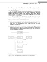
There are fi ve OSPF area types. The position of a router with respect to OSPF areas
is important as well. The area types are shown in Figure 14.5.
The OSPF Area 0 (0.0.0.0) is very special. This is the backbone area of an OSPF
routing domain. An OSPF routing domain (AS) can consist of a single area, but in that
case the single area must be Area 0. Only the backbone area can generate the summary
routing topology information that is used by the other areas. This is why all interarea
traffi c must pass through the backbone area. (There are backdoor links that can be
confi gured on some routers to bypass the backbone area, but these violate the OSPF
specifi cation.) In a sense, the backbone area knows everything. Not so long ago, only
powerful high-end routers could be used on an OSPF backbone. On the Illustrated Net-
work, each AS consists of only an Area 0.
If an area is not the backbone area, it can be one of four other types of areas. All of
these areas connect to the backbone area through an Area Border Router (ABR). An
ABR by defi nition has links in two or more areas. In OSPF, routers always form the
boundaries between areas. A router with links outside the OSPF routing domain is
called an autonomous system boundary router (ASBR). Routing information about des-
tination IP addresses not learned from OSPF are always advertised by an ASBR. Even
when static routes, or RIP routes, are redistributed by OSPF, that router technically
becomes an ASBR. ASBRs are the source of external routes that are outside of the
368 PART III Routing and Routing Protocols